

Daewoo DTH-20D5FS, DTH-21D4FS Service Manual
Service Manual
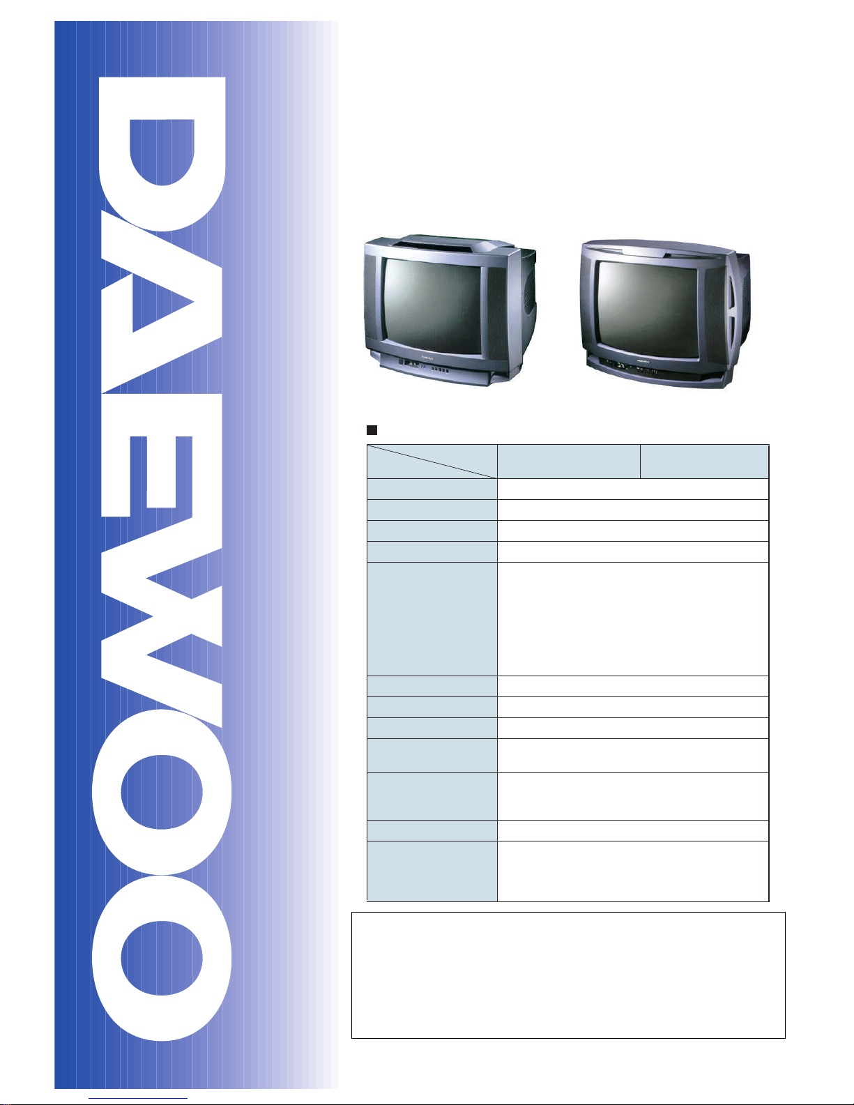
Color Television
CHASSIS : CM-220B
Model : DTH-20D5FS
DTH-21D4FS
http : //svc.dwe.co.kr Sep. 2000
DAEWOO ELECTRONICS CO., LTD.
S/M No. : TCM220MEF0
MODEL
ITEM
TV STANDARD
POWER INPUT
POWER CONSUMPTION
TUNING SYSTEM
TUNING RANGES
SOUND OUTPUT
SPEAKER
ANTENNA INPUT IMPEDANCE
AUXILIARY INPUT TERMINAL
INTERMEDIATE FREQUENCIES
REMOTE CONTROL
SPECIAL FUNCTIONS
DTH-20D5FS
DTH-2104FS
PAL-M/N
220V 50/60 HZ
88W
Frequency Synthesizer (FS) Tuning System
TV
CATV
VHF(L) : CH 2 ~ CH 6
UHF(H) : CH 7 ~ CH 13
UHF : CH 14 ~ CH 69
VHF(L) : 5A, A ,B, A-5 - A-1
CH 2 - CH 6
VHF(H) : C - W +11
CH 7 - CH 13
UHF : W+12 - W +84
5W + 5W
8 ohm 5W x 2EA
75 ohm Unbalanced
Font : Video, Audio, Earphone
Rear : Video, Audio, (R,L)
Picture IF Carrier Frequency : 45.75 MHZ
Sound IF Carrier Frequency : 41.25 MHZ
Color Sub-Carrer Frequency : 3.579545 MHZ
R-43A01
1) ICON MENU TYPE
2) 3-Language OSD
3) WITH CAPTION
4) CH LABEL
SPECIFICATIONS
DTH-20D5FS DTH-21D4FS
✔
Caution
: In this Manual, some parts can be changed for improving, their
performance without notice in the parts list. So, if you need the
latest parts information,please refer to PPL(Parts Price List) in
Service Information Center (http://svc.dwe.co.kr).

1
TABLE OF CONTENTS
SPECIFICATIONS........................................................................................................ 2
CIRCUIT BLOCK KIAGRAM........................................................................................ 3
ALIGNMENT INSTRUCTION........................................................................................ 4
Your Remote Control.................................................................................................................4
Service Mode Adjustment..........................................................................................................5
Assembly Adjustment................................................................................................................6
SCHEMATIC DIAGRAM............................................................................................... 10
EXPLODED VIEW......................................................................................................... 11
PRINTED CIRCUIT BOARD......................................................................................... 13
SERVICE PARTS LIST................................................................................................. 14
TROUBLE SHOOTING GUIDE..................................................................................... 32
1. No Poweer.............................................................................................................................32
2. No Picture..............................................................................................................................33
3. No Sound...............................................................................................................................34
4. CH Don’t Stop........................................................................................................................35
5. No Color.................................................................................................................................36
6. No Vertical Deflection............................................................................................................36
7. No On-Screen Display...........................................................................................................37
8. Remote ControlDoes Not Operate.........................................................................................37
2
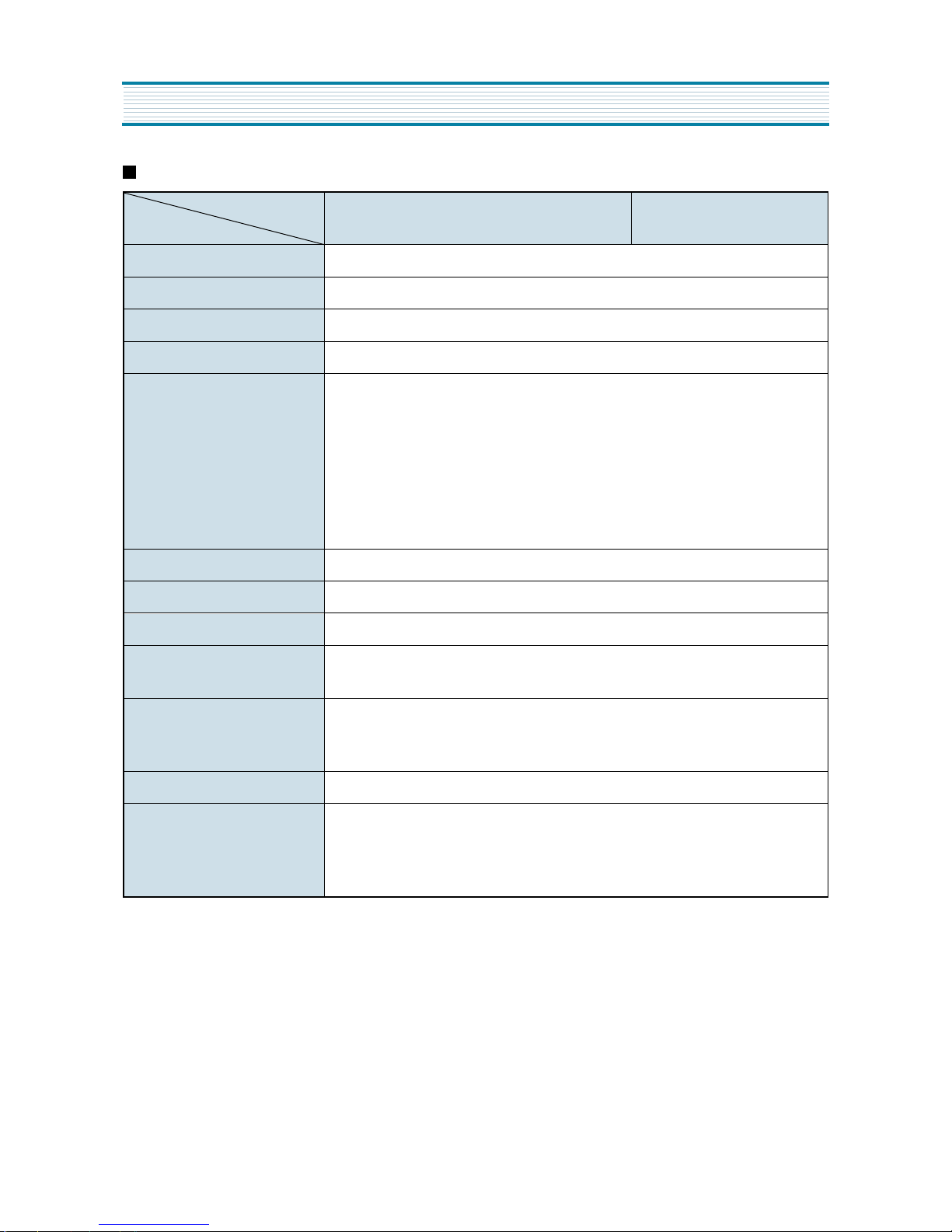
SPECIFICATIONS
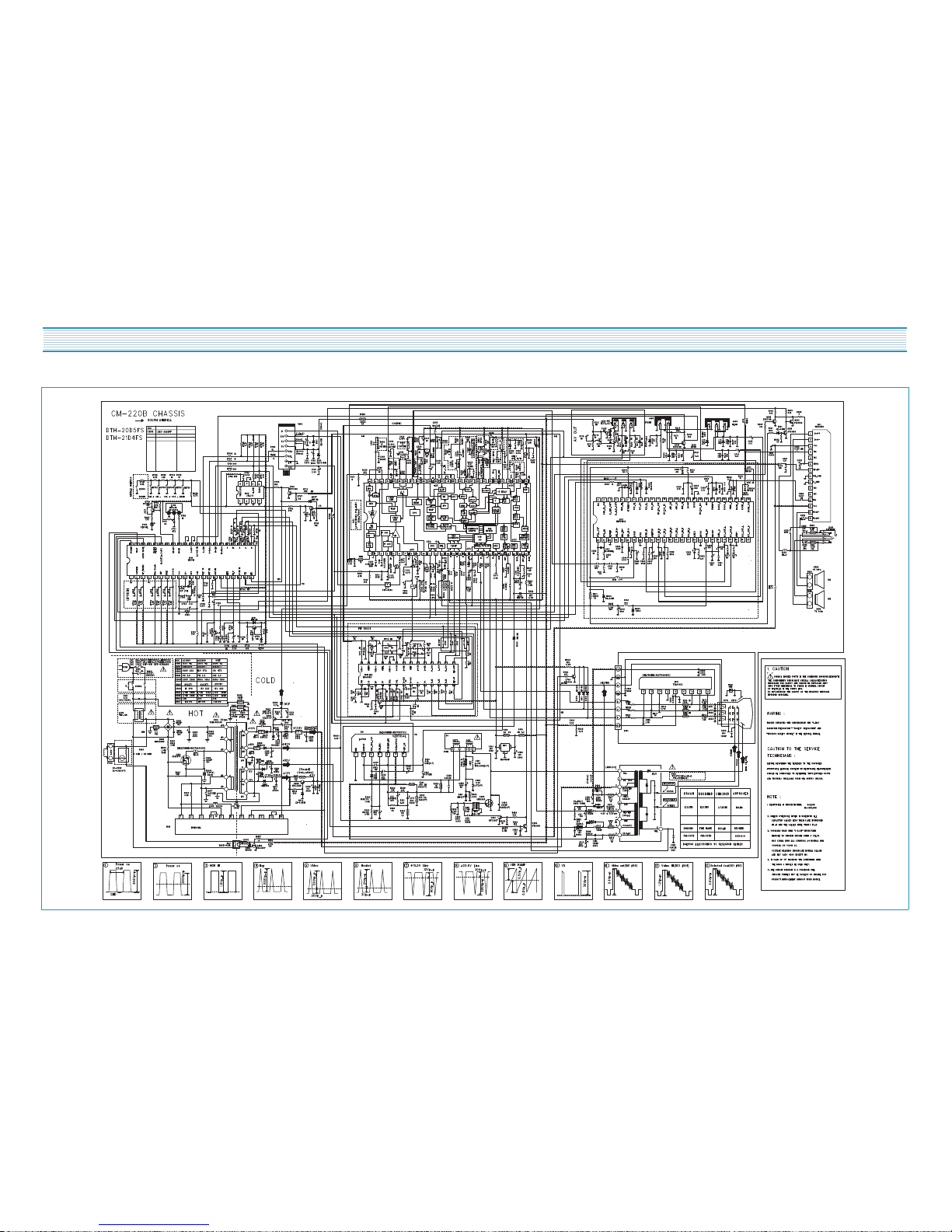
CM-220B
MODEL
ITEM
DTH-20D5FS DTH-21D4FS
TV STANDARD PAL-M/N
POWER INPUT 220V 50/60HZ
POWER CONSUMPTION 88W
TUNING SYSTEM Frequency Synthesizer (FS) Tuning System
TUNING RANGES
TV VHF(L) : CH 2 ~ CH 6
UHF(H) : CH 7 ~ CH 13
UHF : CH 14 ~ CH 69
CATV VHF(L) : 5A, A, B, A-5 - A-1
CH 2 - CH 6
VHF(H) : C - W + 11
CH 7 - CH 13
UHF : W + 12 - W + 84
SOUND OUTPUT 5W + 5W
SPEAKER 8 ohm 5W x 2EA
ANTENNA INPUT IMPEDANCE 75 ohm Unbalanced
AUXILIARY INPUT TERMINAL
Front : Video, Audio, Earphone
Rear: Video, Audio, (R,L)
INTERMEDIATE FREQUENCIES
Picture IF Carrier Frequency : 45.75 MHZ
Sound IF Carrier Frequency : 41.25 MHZ
Color Sub-Carrer Frequency : 3.579545 MHZ
REMOTE CONTROL R - 43A01
SPECIAL FUNCTIONS
1) ICON MENU TYPE
2) 3-Language OSD
3) WITH CAPTION
4) CH LABEL
3
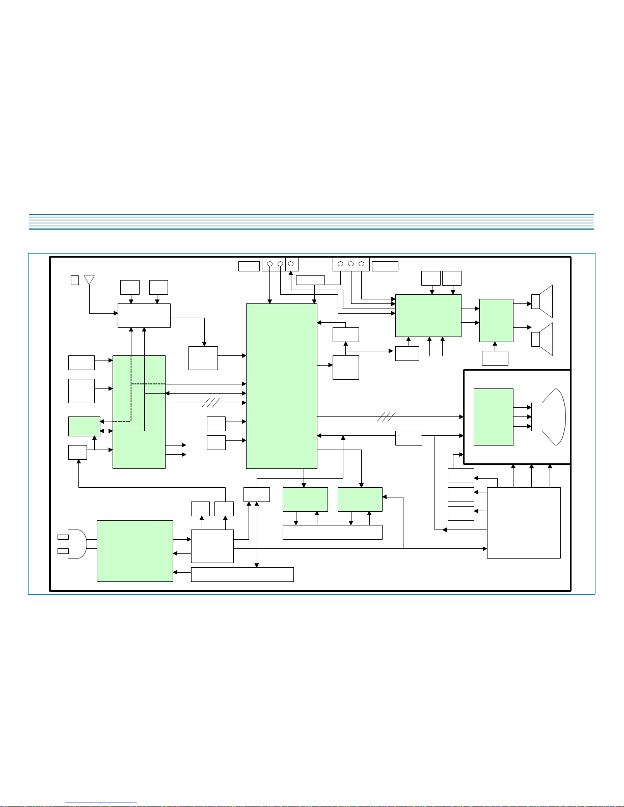
CIRCUIT BLOCK DIAGRAM
V A H V L R
SCL SDA
(1) (2)
OSD RGB
(1)
(2)
TUNER
DT5-NF20F
u-COM IC
LC863240
SCL
SDA
SOUND SCL
SOUND SDA
MAIN IC
DCT814B
SCL
SDA
RGB
SOUND IC
MSP3430G
SCL SDA
Screen Fouse H.V.
FBT
HEATER
POWER IC
2SK2677
EEPROM
IR
SW1 ~
SW5
SAW
FILTER
VIDEO
AMP
TDA6103Q
10V
28V
SOUND
AMP
TDA7266
IF DET.
OUT
TRAP
BPF
5V
9V
5V
X-RAY
SMPS TRANS
TSM-3541A5
DPM001T1A
14V
5V
33V
VERTICAL
LA7841
HOR. OUTPUT
2SD2499
DEFLECTION YOKE
OCP
26V
14V
9V 5V
EARPHONE
A/V IN 2
RF
220V
A/V IN 1
4
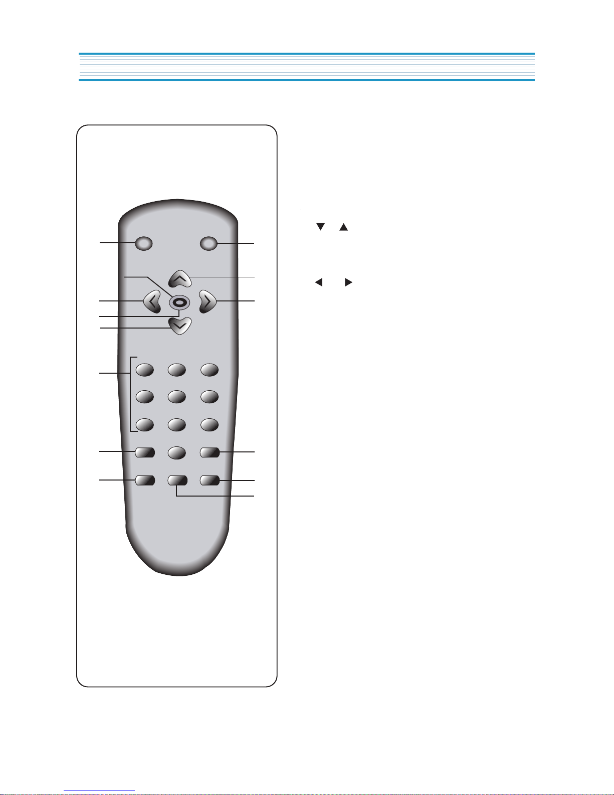
ALIGNMENT INSTRUCTION
1. POWER
use this button to turn your TV on or off.
2. MUTE
Use to turn the TV's sound on and off.
3. CH
Use these buttons to change your TV's volume, to
activate selections in the menu system.
4. VOL
Use thesebuttons to change your TV's volume, to
activate selections in the meny system, or to change
audio and video settings.
5. MENU
Use this button to turn the TV's menu system on and off.
6. DISPLAY
Use this button to display the channel numbeer and
status.
7. INPUT
Use this button to select the TV's signal source.
8. VIDEO
Use this button to display video adjustment.
9. 0-9
Use these buttons to change channels.
10. SLEEP
Use this button to program the TV to turn off after a
certain time.
11. PREVIOUS
Use this button to return to the previous channel you
were watching.
1
3
4
11
8
7
2
4
5
3
9
10
6
POWERMUTE
MENU
CH
SLEEP PREVIOUS
VIDEOINPUTDISPLAY
1 2 3
4 5 6
7 8
0
9
VOL VOL
Your Remote Control
5
SERVICE MODE ADJUSTMENTS
Follow the steps below whenever service adjustment is required. See Table- A and Table- B to determine if
service adjustments are required.
1) How to enter the service mode using the user remote control.
·
Turn the set on.
·
Direct the remote control to the reception window of TV.
·
Push buttons of remote control in sequence as follows.
1 MUTE DISPL
AY
MUTE
·
Then, the screen will appear as follows.
·
Using the channel up or channel down button, select the item you wish to adjust.
(The color of selected item turns into the red.)
·
Press the volume up or down button to enter in the service mode you wish to adjust.
2) How to memorize the adjusted values in the service mode.
·
Must press
DISPLAY
button the state which the screen is displaying each of service
menus
after all adjustments are completed each of all service menu.
Table-A : Adjust the values of service mode when a part is replaced.
PART
REPLACED
ADJUSTMENT
NOTES
NECESSARY UNNECESSARY
I701
(U-COM)
O
Data is stored in I703.
I101
(MAIN)
O
I703
(EEPROM)
O
Initial setting values are written from I701.
Adjusting Items
CRT O Adjust items related to picture tube only.(White Balance adjustment)
S2 SCRN
S5 IFC
S6 GEO
S8 W/B
S9 DP
S12 FACT
S7 PTRN NORMAL
S5 RFAGCD
S6 H.PHASE/V.POSI/V.SIZE
S8 RD/BD/RB/GB/BB
S9 Subbrightness
ALIGNMENT INSTRUCTIONS
6
ALIGNMENT INSTRUCTIONS
Table-B
*
indicates the items with different settings each of sets
ASSEMBLY ADJUSTMENTS
1) SCREEN ADJUSTMENT (S2)
·
Enter the service mode and select service adjustment S2.
·
You cna see the one horizontal line on the screen.
·
Adjust the Screen Control Volume (located on FBT) so that the horizontal line onscreen may be
disappeared.
·
Press the volume up or down button to exit in the screen adjustment mode.
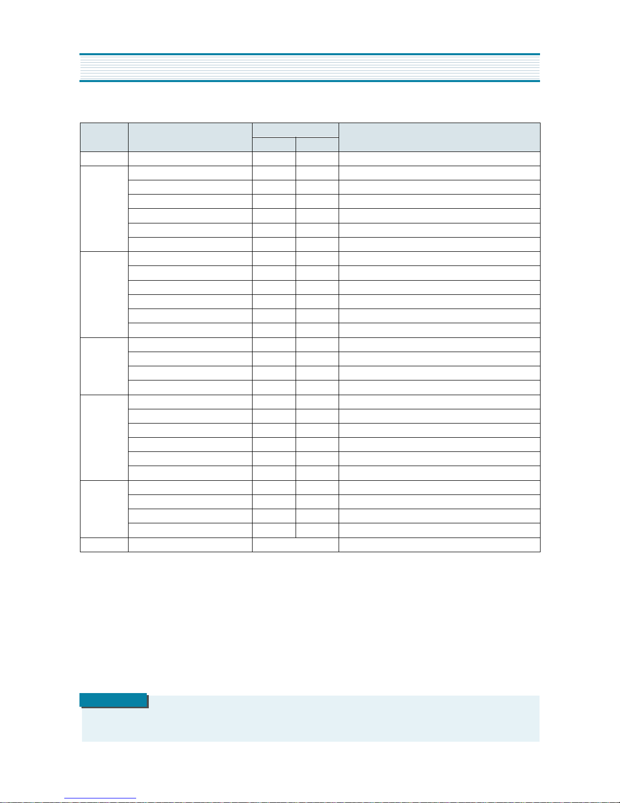
MODE ADJUSTMENT ITEMS
DATA
REMARKS
INITIAL RANGE
S2 Screen Adjustment - -
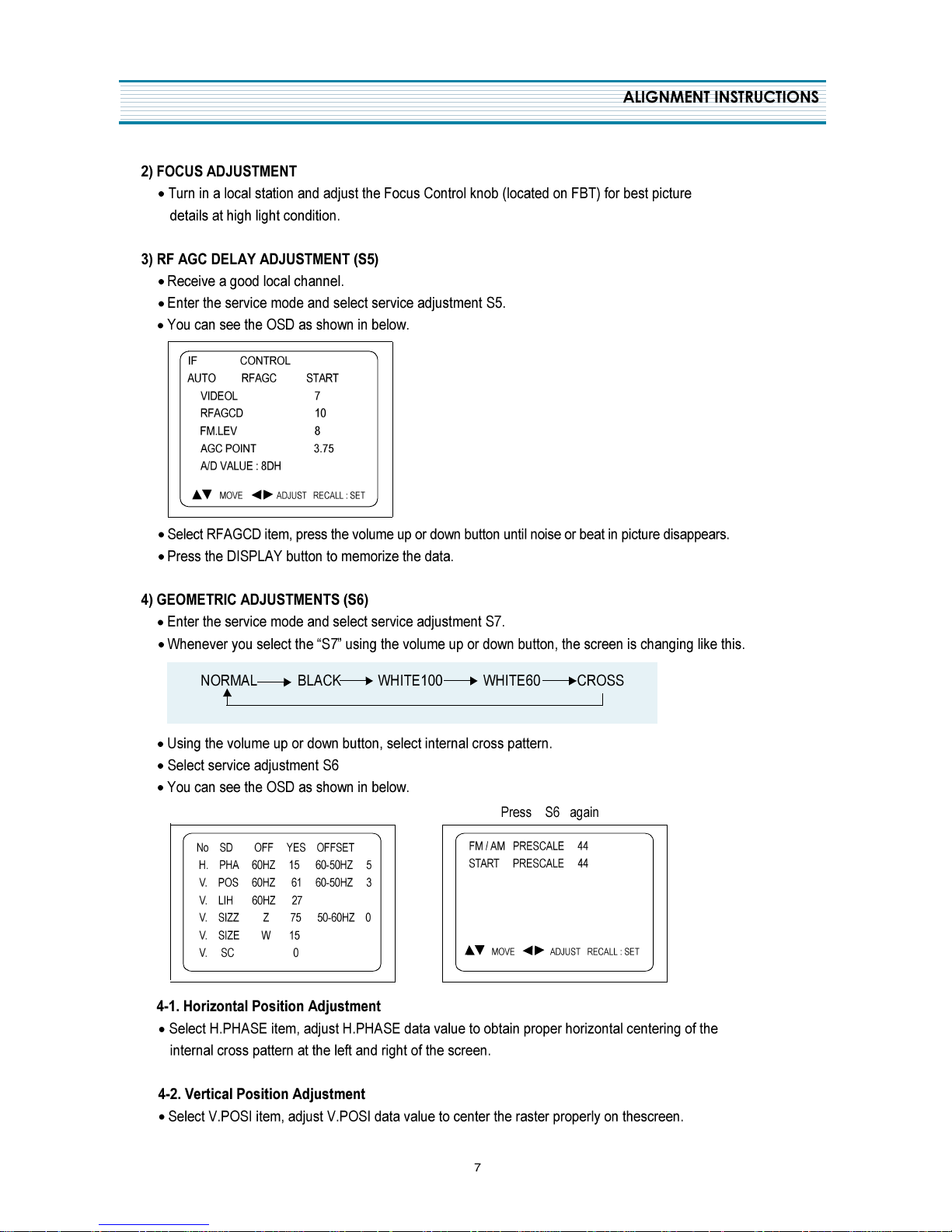
S5
Auto RF AGC - Video Level (VIDEOL) 7 0 ~ 7 Must be set to 7
RF AGC Delay (RFAGCD) * 0 ~ 63 Align RF AGC threshold
FM Level (FM.LEV) 8 0 ~ 31 Must be set to 20
AGC Point 3.75 - Select AGC reference voltage
A/D VALUE - -
S6
Horizontal Phase(H.PHASE) * 0 ~ 31 Align sync to flyback pulse, using internal cross pattern(S7)
Vertical Position (V.POSI) * 0 ~ 63 Align vertical DC bias, using internal cross pattern(S7)
Vertical Size (V.SIZE) * 0 ~ 127 Align vertical amplitude, using internal cross pattern(S7)
NO SD POWER OFF YES - Automatically turn off in 15min for no received signal.
Vertical S-Correction (V SC) 0 0 ~ 31 Must be set to 6
Vertical Linearity (V LIN) 20 0 ~ 31 Must be set to 16
S7
Internal Black - - Display internal BLACK pattern
Internal 100% White - - Display internal 100% WHITE
Internal 60% White - - Display internal 60% WHITE
Internal Cross Pattern - - Display internal CROSS pattern
S8
Red Drive (RD) * 0 ~ 127 Align RED OUT AC level
Green Drive (GD) 10 0 ~ 15 Must be set to 10
Blue Drive (BD) * 0 ~ 127 Align BLUE OUT AC level
Red Bias (RB) * 0 ~ 255 Align RED OUT DC level
Green Bias (GB) * 0 ~ 255 Align GREEN OUT DC level
Blue Bias (BB) * 0 ~ 255 Align BLUE OUT DC level
S9
Subbrightness * 0 ~ 127 Align common RGB DC level
Contrast 10 0 ~ 27
Tint 27 0 ~ 27
Color 15 0 ~ 27
S12 Forwarding Mode - Factory Initialization
IN THE SCREEN ADJUSTMENT MODE, DONT PRESS OTHER BUTTONS EXCEPT VOLUME UP OR DOWN BUTTON.
NOTE
8
ALIGNMENT INSTRUCTIONS
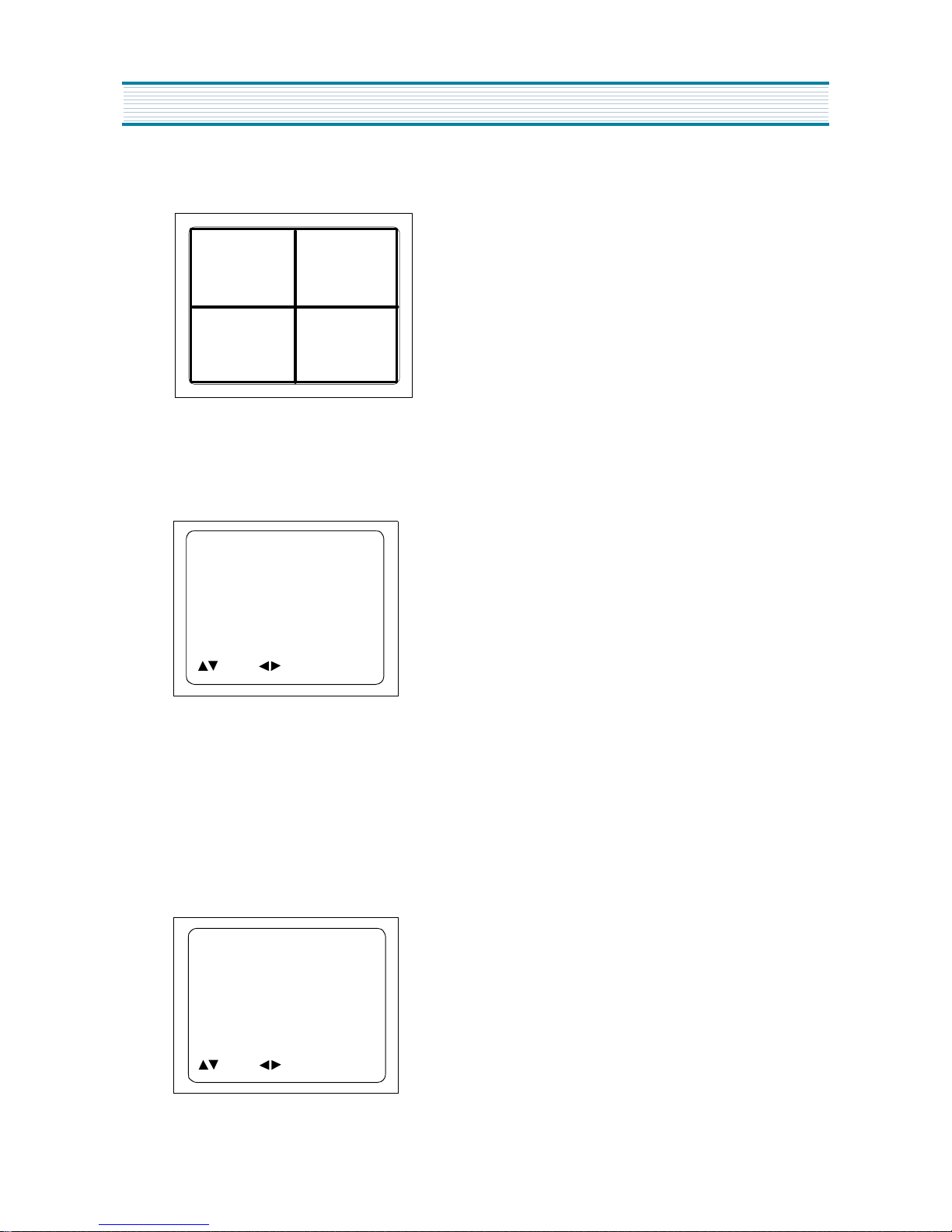
4-3. Vertical Size Adjustment
·
Select “ V.SIZE” item, adjust “ V.SIZE” data value to proper vertical size as follows.
5) WHITE BALANCE ADJUSTMENT(S8)
·
Receive a good local channel.
·
Enter the service mode and select service adjustment S8.
·
You can see the OSD as shown in below.
·
Using volume up or volume down, adjust service adjustment data of RD/GD/BD and RB/GB/BB until a good gray
scale with normal whites is obtained.ALIGNMENT INSTRUCTIONS
·
Press the DISPLAY button to memorize the data.
6) DIGITAL PRESET(D.P) ADJUSTMENTS(S9)
SUBBRIGHTNESS ADJUSTMENT
·
Receive a good local channel.
·
Enter the service mode and select service adjustment S9.
·
You can see the OSD as shoown in below.
RD 58
GD 10
BD 65
RB 105
GB 160
BB 100
MOVE ADJUST RECALL : SET
D.P.
SUB BRIGHTNESS 64
CONTRAST 10
TINT 27
COLOR 15
MOVE ADJUST RECALL : SET

9
ALIGNMENT INSTRUCTIONS
·
Select Subbrightness item, adjust Subbrightness data value
to obtain normal
brightness level.
·
Press the DISPLAY button to memorize the data.
CONTRAST
·
Fixed value = 10
TINT
·
Fixed value = 27
COLOR
·
Fixed value = 15
7) FACTORY OUTGOING MODE (S12 : FACT)
·
If you select the S12, then the set becomes factory outgoing status.
·
You can see the OSD “outgoing OK”
10
CM-220B CHASSIS
SCHEMATIC DIAGRAM
11
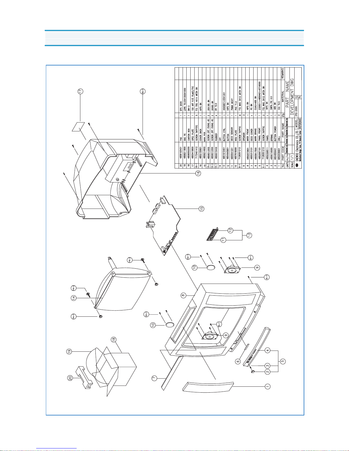
EXPLODED VIEW
DTH-20D5FS
 Loading...