

Page 1

S/G No. : CM003P-010G1
Service Guide
Color Television
CHASSIS : CM-003
Model :
DTH-14V1FS
DTH-20V1FS
DTH-21V1FS
DTH-14V3FS
DTH-20V3FS
DTH-21V3FS
DTH-14V4FS
DTH-20V4FS
DTH-21V4FS
DTH-14V1FC
DTH-14V3FC
Features
181CH quartz frequency synthesis tuning system
On-Screen Display(Simple Icon Type/Trilingual : Eug/Span/Fre n)
Programmable channel skip memory
24 hour programmable TV on/off function
Convenient sleep timer
Built-in Closed Caption
Full function infrared remote control
DTH-20V4FC
POWER
MUTE
CH
VOLVOL
CH
DISPLAY INPUT VIDEO
1 2 3
4 5 6
7 809
SLEEP PREVIOUS
R-38T01
Specifications
Model Name
Screen Size 14" 20" 21"
Channel Coverage
Power Source
Power Consumption
Set Dimensions
(W H D)
Net Weight
Stuffing Q'th(48ft)
DTH-14V1/V3/V4FS DTH-20V1/V3/V4FS DTH-21V1/V3/V4FS
VHF 2-13
UHF 14-69
113 Cable Ch.
AC 100-260, 50/60Hz AC 100-260, 50/60Hz AC 100-260, 50/60Hz
63W 70W 73W
336 x 338 x 376(mm)
8.7Kg 16.3Kg 19Kg
1100Set 540Set
VHF 2-13
UHF 14-69
113 Cable Ch.
VHF 2-13
UHF 14-69
113 Cable Ch.
516x469(6)(4)x482(6)(2)(mm)496x446(2)(2)x464(4)(3)(mm)
DAEWOO ELECTRONICS CO., LTD
http : //svc.dwe.co.kr
Sep. 1999
Page 2
Important Service Notes
1. X-ray Radiation Rrecaution
1) Excessive high voltage can produce potentially hazardous X-RAY RADIATION. To avoid such hazards, the high voltage must not be above the specified limit. The nominal value of the high voltage of this receiver is
25.5kv(20”/21”) & 23.5kv(14”)at zero beam current (minimum brightness)
under a 120V/220V AC power source. The high voltage must not, under any
circumstances, exceed 28kv(20”/21”) & 26kv(14”). Each time a receiver
requires servicing, the high voltage should be checked following the HIGH
VOLTAGE CHECK procedure on page 10 of this manual. It is recommended as a parts of the service record. It is important to use an accurate
and reliable high voltage meter.
2) This receiver is equipped with X-RADIATION PROTECTION circuit which
prevents the receiver from producing an excessively high voltage even if the
B+voltage increases abnormally. Each time the receiver is serviced, XRADIATION PROTECTION circuit must be checked to determine that the
circuit is properly functioning, following the X-RADIATION PROTECTION
CIRCUIT CHECK procedure on page 6 of this manual.
3) The only source of X-RAY RADIATION in this TV receiver is the picture tube.
For continued X-RAY RADIATION protection, the replacement tube must
be exactly the same type tube as specified in the parts list.
4) Some parts in this receiver have special safety-related characteristics for XRAY RADIATION protection. For continued safety, parts replacement
should be undertaken only after referring to the PRODUCT SAFETY
NOTICE below.
2. Safety Precaution
WARNING: Service should not be attempted by anyone unfamiliar with the
necessary precaution on this receiver. The following are the necessary precaution to be observed before servicing.
1) Since the chassis of this receiver has hazardous potential to ground whenever the receiver is plugged in (floating chassis), an isolation transformer
must be used during servicing to avoid shock hazard.
2) Always discharge the picture tube anode to the CRT conductive coating the
picture tube. The picture tube is highly evacuated and if broken, glass fragments will be violently expelled. Use shatterproof goggles and keep picture
tube away from the body while handling.
3) When placing chassis in the cabinet, always be certain that all the protective
devices are put back in place, such as; nonmetallic control knobs, insulating covers, shields, isolation resistor-capacitor network, etc.
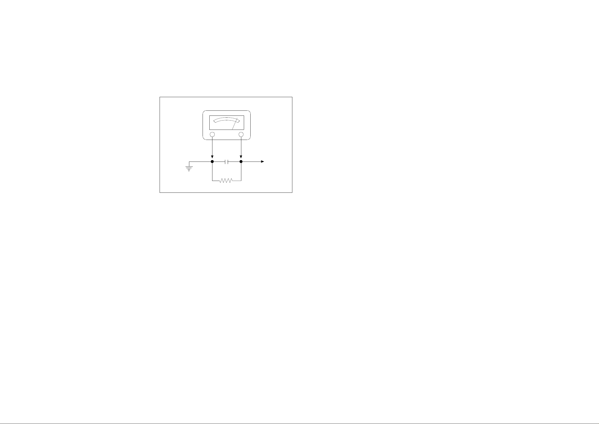
4) Before returning the set to the customer, always perform an AC leakage current check on the exposed metallic parts of the cabinet, such as antennas,
terminals, screw-heads, metal overlays, control shafts etc. to be sure the set
is safe to operate without danger of electrical shock. Plug the AC line cord
directly into a 120V AC outlet (do not use a line isolation transformer during
this check). Use an AC voltmeter having 5000 ohms per volt or more sensitivi-ty in the following manner.
Connect at 1500 ohm 10 watt resistor, paralleled by a 0.15 mfd. AC type
capacitor, between a known good earth ground (water pipe, conduit etc.)
and the exposed metallic parts, one at a time. Measure the AC voltage
across the combination of 1500 ohm resistor and 0.15 mfd capacitor. Voltage measured must not exceed 0.3 volts RMS. This corresponds to 0.2 millliamp. AC. Any value exceeding the limit constitutes a potential shock
hazard and must be corrected immediately.
AC VOLT METER
0.15MFD
Place this probe
on each exposed
metallic part.
Good earth ground
such as d water
pipe, conduit, etc.
1500 ohm
10watt
3. Product Safety Notice
Many electrical and mechanical parts in this chassis have special safety-related
characteristics. These characteristics are often passed unnoticed by a visual
inspection and the protection afforded by them cannot necessarily be obtained
by using replacement components rated for higher voltage, wattage, etc.
Replacement parts which have these special safety characteristics are identified in this manual and its supplements; electrical components having such features are identified by shading on the schematic diagram and the parts list.
Before replacing any of these components, read the parts list in this manual
carefully. The use of substitute replacement parts which do not have the same
safety characteristics as specified in the parts list may create X-ray radiation or
other hazards.
4. Service Notes
1) When replacing parts or circuit boards, clamp or bend the lead wires to terminals before soldering.
2) When replacing a high wattage resistor (metal oxide film resistor) in the circuit board, keep the resistor min 1/2 inch away form circuit board.
3) Keep wires away from high voltage or high temperature components.
DAEWOO ELECTRONICS CO., LTD.
C.P.OBOX8003 SEOUL, KOREA
Tel : 82-2-360-8179
Fax : 82-2-360-8184
E-mail : G7F00E@dwe.web.co.kr
Printed in Nov. 1998
Page 3

Parts Location on Main Board(Solder Side)
T
S
R
Q
P
O
N
M
L
K
J
I
H
G
F
E
D
C
B
A
Y
2
4 7
9 11
12 15
16 19 201 3 5 6 8 10 13 14 17 18
X
LOC X Y
CONDENSOR
C101 2 P
C102 2 Q
C103 2 R
C104 5 O
C105 5 P
C106 5 N
C107 5 N
C301 7 Q
C302 5 Q
C303 7 P
C305 5 R
C307 6 P
C308 7 P
C310 8 Q
C311 7 Q
C401 15 L
C403 17 L
C404 18 N
C405 13 M
C406 15 M
C408 9 N
C410 10 Q
C411 10 S
C412 12 R
C413 12 S
C414 9 R
C415 10 R
C416 12 Q
C417 11 S
C418 14 S
C451 10 P
C452 10 Q
C501 6 N
C502 5 L
C507 5 K
C508 2 L
C509 5 L
C510 5 K
C511 5 K
C512 2 P
C513 2 N
C514 3 M
C515 2 M
C516 2 M
C517 3 L
C518 2 O
C519 3 K
C520 3 K
C521 4 K
C523 3 K
C524 2 P
C525 2 N
C601 5 O
C602 2 J
C603 3 G
C604 3 H
C605 3 H
C701 9 B
C702 8 F
C703 9 D
C704 8 D
C705 8 E
C706 14 C
C707 13 D
C708 8 D
C801 16 D
C802 14 F
C803 17 H
C804 17 J
C805 13 I
C806 12 J
C812 9 I
C813 9 K
C814 11 M
C815 8 L
C818 10 N
C819 8 N
C820 12 P
C826 13 B
C832 10 I
C880 14 K
C881 11 H
C902 3 B
C905 3 B
C965 1 C
CC151 3 R
CC152 5 O
CC153 4 N
CC154 4 N
CC155 4 N
CC528 3 N
CC551 4 M
CC552 4 M
CC556 3 O
CC558 3 N
LOC X Y
CC560 4 M
CC562 3 L
CC564 4 M
CC565 4 L
CC567 4 K
CC568 4 L
CC569 3 O
CC570 5 M
CC571 5 M
CC573 5 M
CC574 4 M
CC575 4 L
CC577 4 M
CC578 4 M
CC579 4 M
CC580 3 O
CC582 4 L
CC662 3 G
CC663 2 I
CC752 7 G
CC753 8 G
CC754 7 F
CC755 7 F
CC756 9 C
CC757 7 F
CC758 6 G
CC759 6 G
CC760 6 G
CC761 7 G
CC762 7 G
CC765 7 H
CC766 7 H
CC767 7 F
CC768 6 F
CC780 8 C
CC801 11 J
CC900 2 B
CCA01 7 B
CCA02 4 M
DIODE
D101 4 Q
D105 4 Q
D301 6 R
D401 14 L
D404 18 N
D405 12 Q
D406 12 S
D407 12 R
D408 12 R
D409 19 K
D501 6 N
D502 8 K
D503 4 R
D504 8 J
D505 4 R
D701 9 E
D703 11 A
D704 9 E
D757 10 D
D801 15 F
D807 10 L
D808 9 L
D812 13 C
D813 9 J
D822 10 L
IC
I101 5 O
I301 6 Q
I401 9 P
I601 2 I
I701 8 H
I703 8 D
I801 11 G
I901 2 A
IL701 10 A
COIL
L111 4 P
L112 6 O
L401 13 N
L501 3 N
L502 4 O
L533 2 N
L701 11 E
L800 13 F
L801 15 D
L802 13 I
L805 11 P
L807 10 K
L808 9 K
TRANSISTOR
Q401 15 L
Q402 18 L
Q403 9 N
Q503 8 L
Q601 3 I
Q701 10 D
LOC X Y
Q702 10 D
Q703 9 D
Q704 9 E
Q706 12 C
Q707 13 C
Q801 14 J
Q804 11 N
Q805 12 D
QV01 9 B
RESISTOR
R301 7 R
R302 8 R
R303 8 R
R305 8 R
R352 6 Q
R353 7 Q
R401 15 L
R402 14 M
R403 14 L
R405 14 L
R411 13 Q
R412 13 S
R413 13 R
R414 13 R
R416 18 L
R418 10 P
R419 9 Q
R420 4 R
R425 9 M
R451 10 S
R452 4 S
R501 8 J
R502 6 K
R511 6 M
R515 7 D
R555 6 N
R601 2 I
R602 6 B
R604 4 H
R605 6 I
R701 10 B
R708 11 D
R709 14 C
R712 11 D
R736 9 E
R743 13 C
R744 14 C
R746 14 C
R747 15 C
R750 11 C
R775 11 C
R776 11 B
R780 7 D
R785 7 E
R789 2 R
R790 2 R
R799 9 F
R801 15 G
R801A 16 G
R802 15 H
R803 14 H
R804 15 I
R805 13 G
R809 17 H
R813 10 O
R814 11 O
R817 13 D
R818 13 D
R820 7 N
R822 9 M
R880 16 K
R883 19 H
R888 16 B
R910 3 C
R911 2 C
R912 3 C
R913 3 B
R914 2 B
R915 1 B
RC105 5 M
RC111 3 P
RC150 5 O
RC151 5 O
RC154 5 N
RC156 4 N
RC165 6 O
RC351 7 P
RC359 8 Q
RC360 8 Q
RC361 8 Q
RC362 7 Q
RC426 8 M
RC453 9 N
RC454 14 L
RC455 14 L
RC503 7 N
LOC X Y
RC506 7 K
RC507 7 L
RC508 7 J
RC509 7 I
RC510 2 N
RC520 2 M
RC525 3 L
RC526 4 L
RC530 3 M
RC531 3 M
RC533 2 N
RC554 7 N
RC557 5 K
RC558 3 O
RC559 2 O
RC561 3 N
RC562 4 N
RC563 2 L
RC565 3 J
RC566 3 J
RC567 4 L
RC568 4 K
RC569 4 J
RC570 4 K
RC571 4 L
RC572 4 K
RC573 4 L
RC655 2 G
RC656 3 H
RC703 8 C
RC704 6 H
RC705 7 I
RC706 7 I
RC707 6 H
RC731 10 C
RC732 6 H
RC733 6 G
RC734 5 G
RC735 6 F
RC737 9 E
RC738 10 E
RC740 7 E
RC751 8 C
RC752 8 B
RC756 8 G
RC759 8 H
RC762 12 C
RC763 11 B
RC766 8 K
RC770 8 H
RC781 9 C
RC782 7 F
RC784 8 F
RC786 7 G
RC787 8 B
RC788 8 B
RC790 8 G
RC791 5 F
RC792 5 G
RC793 5 G
RC794 5 G
RC795 10 D
RC796 10 D
RC797 10 C
RC861 13 B
RC862 8 N
RC913 2 B
RC914 2 B
RC915 1 B
RC923 2 A
RC924 2 A
RC925 1 A
RCA01 7 B
RCA02 7 B
RCA03 2 M
RCA04 1 M
RCV02 8 B
RLY1 19 K
RS801 19 D
OTHERS
SF101 5 Q
SW701 18 A
SW702 17 A
SW703 16 A
SW704 14 A
SW705 13 A
SW706 12 A
SW801 19 D
SW802 18 D
T401 16 L
T402 16 Q
T801 11 K
U102 3 S
X502 3 L
XC701 8 G
Z501 2 O
Page 4

Alignment Instructions
1. Service Mode Adjustments
Follow the steps below whenever service adjustment is required. See Table- A and Table- B to determine if
service adjustments are required.
1) How to enter the service mode using the user remote control.
• Turn the set on.
• Direct the remote control to the reception window of TV.
• Push buttons of remote control in sequence as follows.
1 → MUTE → DISPLAY → MUTE
• Then, the screen will appear as follows.
S2 SCRN
S5 IFC
S6 GEO
S8 W/B
S9 DP
S12 FACT
S7 PTRN NORMAL
• Using the channel up or channel down button, select the item you wish to adjust.
(The color of selected item turns into the red.)
• Press the volume up or down button to enter in the service mode you wish to adjust.
2) How to memorize the adjusted values in the service mode.
• Must press DISPLAY button the state which the screen is displaying each of service menus
after all adjustments are completed each of all service menu.
TABLE-A
TABLE-B
MODE ADJUSTMENT ITEMS
S2 Screen Adjustment - -
Auto RF AGC - Video Level (VIDEOL) 7 0 ~ 7 Must be set to 7
RF AGC Delay (RFAGCD) * 0 ~ 63 Align RF AGC threshold
FM Level (FM.LEV) 8 0 ~ 31 Must be set to 8
S5
S6
S7
S8
S9
S12 Forwarding Mode - Factory Initialization
AGC Point 3.75 - Select AGC reference voltage
A/D VALUE - Horizontal Phase(H.PHASE) * 0 ~ 31 Align sync to flyback pulse
Vertical Position (V.POSI) * 0 ~ 63 Align vertical DC bias
Vertical Size (V.SIZE) * 0 ~ 127 Align vertical amplitude
NO SD POWER OFF YES - Automatically turn off in 15min for no received signal.
Vertical S-Correction (V SC) 0 0 ~ 31 Must be set to 0
Vertical Linearity (V LIN) 16 0 ~ 31 Must be set to 16
Internal Black - - Display internal BLACK pattern
Internal 100% White - - Display internal 100% WHITE
Internal 60% White - - Display internal 60% WHITE
Internal Cross Pattern - - Display internal CROSS pattern
Red Drive (RD) * 0 ~ 127 Align RED OUT AC level
Green Drive (GD) 10 0 ~ 15 Must be set to 10
Blue Drive (BD) * 0 ~ 127 Align BLUE OUT AC level
Red Bias (RB) * 0 ~ 255 Align RED OUT DC level
Green Bias (GB) * 0 ~ 255 Align GREEN OUT DC level
Blue Bias (BB) * 0 ~ 255 Align BLUE OUT DC level
Subbrightness * 0 ~ 127 Align common RGB DC level
Contrast 27 0 ~ 27
Tint 15 0 ~ 27
Color 27 0 ~ 27
INITIAL RANGE
DATA
REMARKS
PART REPLACED
NECESSARY UNNECESSARY
I701
(U-COM)
I101
(MAIN)
I703 (EEPROM) O
CRT O Adjust items related to picture tube only.
ADJUSTMENT
Data is stored in I703.
O
O
Initial setting values are written from I701.
Adjusting Items
S5 RFAGCD
S6 H.PHASE/V.POSI/W.SIZE
S8 RD/BD/RB/GB/BB
S9 Subbrightness
* indicates the items with different settings each of sets
NOTES
2. Assembly Adjustments
1) SCREEN ADJUSTMENT (S2)
• Enter the service mode and select service adjustment S2.
• Adjust the Screen Control Volume (located on FBT) so that the horizontal line onscreen may be
disappeared.
• Press the volume up or down button to exit in the screen adjustment mode.
NOTE
IN THE SCREEN ADJUSTMENT MODE, DONT PRESS OTHER BUTTONS EXCEPT VOLUME UP OR DOWN BUTTON.
Page 5
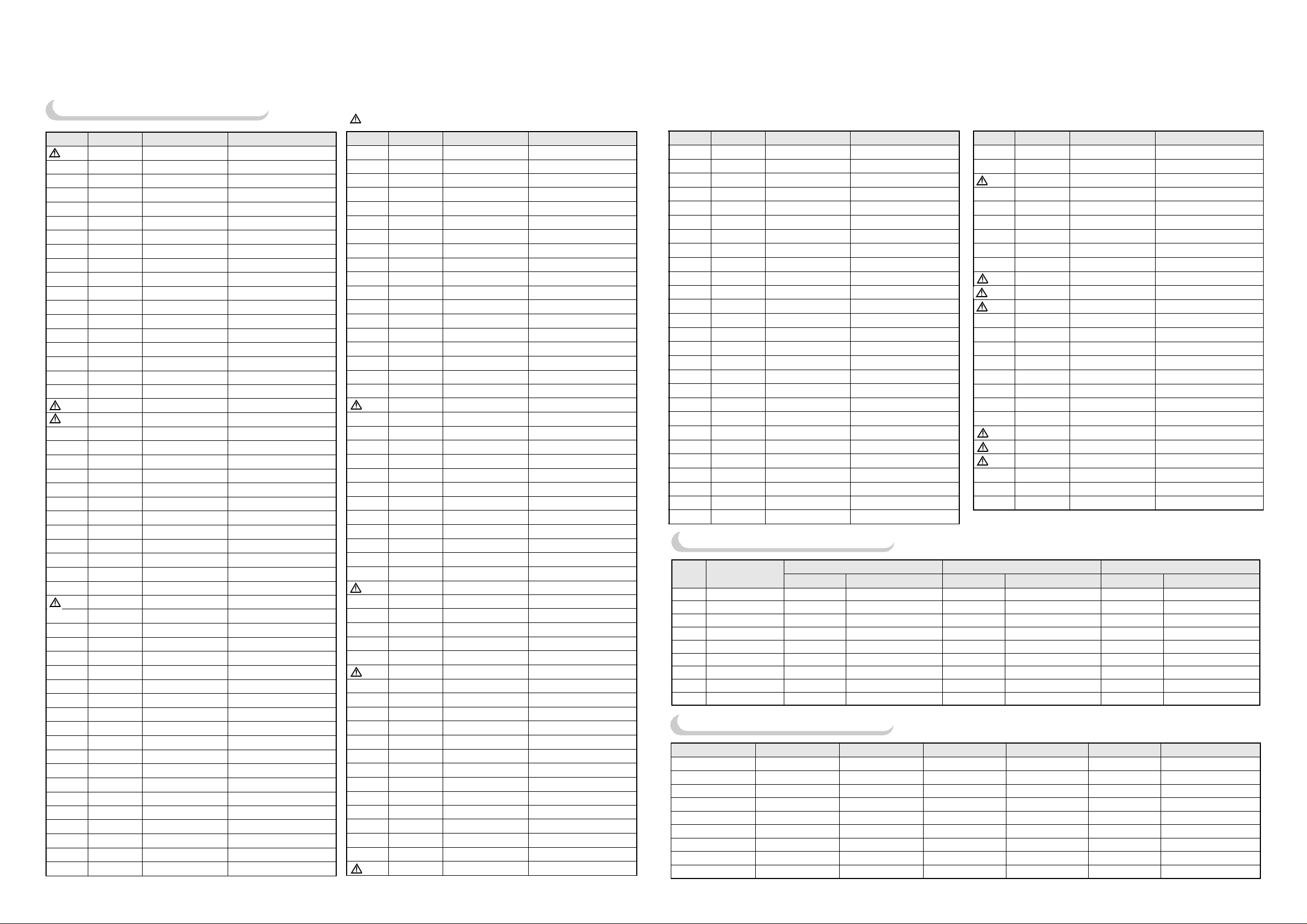
Parts List
Key Parts List (DTH-20V1FS)
is a recommendable part for stock.
®
is safety component, so it must be used the same component.
LOC PART CODE PART NAME DESCRIPTION
ZZ100 48B3738T01
®
ZZ131 58G0000122 COIL DEGAUSSING DC-2030
ZZ132 48519A5110 CRT GROUND NET 2001S-1015-1P
ZZ202 PTSPPWH394 SPEAKER AS DTQ-14P2FC
®
ZZ290 PTMPMSJ666 PCB MAIN MANUAL AS DTQ-20P2FC
®
C403 CEXF2C109V C ELECTRO 160V RSS 1MF (6.3X11) TP
C404 CMYH3C662H C MYLAR 1.6KV BUP 6600PF H
C405 CEXF2C109V C ELECTRO 160V RSS 1MF (6.3X11) TP
C406 CMYE2D514J C MYLAR 200V PU 0.51MF J
C410 CEXF2E100V C ELECTRO 250V RSS 10MF (10X20) TP
C411 CEXF1H100V C ELECTRO 50V RSS 10MF (5X11) TP
C412 CCXB2H102K C CERA 500V B 1000PF K (TAPPING)
C413 CCXB2H102K C CERA 500V B 1000PF K (TAPPING)
C414 CEXF1V471V C ELECTRO 35V RSS 470MF (10X20) TP
C415 CEXF1C102V C ELECTRO 16V RSS 1000MF (10X20) TP
C416 CCXB2H102K C CERA 500V B 1000PF K (TAPPING)
C417 CCXB2H102K C CERA 500V B 1000PF K (TAPPING)
C801 CL1UC3104M C LINE ACROSS WORLD AC250V 0.1UF M R.47
C802 CCXB2H222K C CERA 500V B 2200PF K (TAPPING)
C803 CCXB2H222K C CERA 500V B 2200PF K (TAPPING)
C804 CEYN2E221P C ELECTRO 250V LHS 220MF (22X30)
C805 CMYU3A472J C MYLAR 1KV BCP 4700PF J
C806 CCXB3A102K C CERA 1KV B 1000PF K (TAPPING)
C812 CEXF1C102V C ELECTRO 16V RSS 1000MF (10X20) TP
C813 CBXB3D471K C CERA SEMI 2KV BL(N) 470PF K (T)
C814 CEXF2C101V C ELECTRO 160V RSS 100MF (16X25) TP
C815 CEXF2A100V C ELECTRO 100V RSS 10MF (6.3X11) TP
C818 CEXF1C101V C ELECTRO 16V RSS 100MF (6.3X11) TP
C819 CEXF1H479V C ELECTRO 50V RSS 4.7MF (5X11) TP
C820 CEXF2C101V C ELECTRO 160V RSS 100MF (16X25) TP
C832 CBXB3D471K C CERA SEMI 2KV BL(N) 470PF K (T)
C880 CH1BFE222M C CERA AC U/C/V AC400V 2200PF
C881 CH1HFE102M C CERA AC 4.0KV 1000PF E DG
C902 CMXL2E104K C MYLAR 250V MEU 0.1MF K
C905 CMXL1J224J C MYLAR 63V MEU 0.22MF J (TP)
C965 CCXB3D102K C CERA 2KV B 1000PF K (TAPPING)
D101 DUZ33B---- DIODE ZENER UZ-33B
D301 D1N4003--- DIODE 1N4003 (TAPPING)
D401 D1N4937GP- DIODE 1N4937GP (TAPPING)
®
D405 D1N4937GP- DIODE 1N4937GP (TAPPING)
D406 D1N4937GP- DIODE 1N4937GP (TAPPING)
D407 D1N4937GP- DIODE 1N4937GP (TAPPING)
D408 D1N4937GP- DIODE 1N4937GP (TAPPING)
D409 D1N4148--- DIODE 1N4148 (TAPPING)
D501 D1N4148--- DIODE 1N4148 (TAPPING)
D502 D1N4148--- DIODE 1N4148 (TAPPING)
D503 DUZ9R1BM-- DIODE ZENER UZ-9.1BM 9.1V
D504 D1N4148--- DIODE 1N4148 (TAPPING)
D505 DUZ9R1BM-- DIODE ZENER UZ-9.1BM 9.1V
D701 D1N4148--- DIODE 1N4148 (TAPPING)
D704 DUZ3R9B--- DIODE ZENER UZ-3.9B
D757 D1N4148--- DIODE 1N4148 (TAPPING)
TRANSMITTER REMOCON
R-38T01
LOC PART CODE PART NAME DESCRIPTION
D801 DPBS208GUF DIODE BRIDGE PBS208GU-CA (FORMING)
®
D807 DRGP15J--- DIODE RGP15J
®
D808 DRGP15J--- DIODE RGP15J
D812 DUZ5R6BM-- DIODE ZENER UZ-5.6BM(TAPPING)
D813 DRGP15J--- DIODE RGP15J
D822 DR2M------ DIODE ZENER R2M
F801 5F1GB4021L FUSE GLASS TUBE UL/CSA TL 4A 125V MF51
F801A 4857415001 CLIP FUSE PFC5000-0702
F801B 4857415001 CLIP FUSE PFC5000-0702
I101 1LA76805-- IC MAIN LA76805
®
I301 PTC2SW7101 HEAT SINK ASS`Y 1LA7841--- + 7174300811
I301 1LA7841--- IC VERTICAL LA7841
®
I301A 4857027101 HEAT SINK SPCC T1.0+SN
I301B 7174300811 SCREW TAPPTITE TT2 RND 3X8 MFZN
I401 1K1A7805P1 IC REGULATOR KIA7805PI
I601 1TDA7056A- IC AMP TVA7056A
®
I701 1DW8632CM1 IC MICOM 1DW863228V-CM1
®
I703 124LC02B-- IC MEMORY 24LC02B
®
I801 4850M04710 MODULE POWER DPM001T1A
®
I901 PTA2SW5400 HEAT SINK ASS`Y 1TDA6103Q- + 7174300811
I901 1TDA6103Q- IC VIDEO TDA6103Q
®
I901A 4857025400 HEAT SINK A1050P-H24 T2.0
I901B 7174300811 SCREW TAPPTITE TT2 RND 3X8 MFZN
IL701 1KRT30---- IC PREAMP KRT30
L111 58C5580019 COIL CHOKE TRF-9225 (0.55UH)
L112 5CPZ220K02 COIL PEAKING 22UH K (AXIAL 3.5MM)
L501 58N0000042 COIL VCO TRF-V008
L502 5CPZ100K02 COIL PEAKING 10UH K (AXIAL 3.5MM)
L533 5CPZ150K02 COIL PEAKING 15UH K (AXIAL 3.5MM)
L701 5CPZ220K02 COIL PEAKING 22UH K (AXIAL 3.5MM)
L800 58Q0000093 COIL DELAY LINE RS208
L801 5PTLF106-- FILTER LINE TLF-106
L802 5MC0000100 COIL BEAD HC-3550
L805 58CX430599 COIL CHOKE AZ-9004Y 940K TP
L807 5MC0000100 COIL BEAD HC-3550
L808 5MC0000100 COIL BEAD HC-3550
PW000 4859900321 CORD POWER KKP-8W SPT-2#18AWG(ST)
PWC1 4859902910 CORD POWER ASS`Y
®
Q401 TKSC2330Y- TR KSC2330Y (TP)
Q402 PTA2SW7200 HEAT SINK ASS`Y T2SD2499-- + 7174301011
®
Q402 T2SD2499-- TR 2SD2499
Q402A 4857027200 HEAT SINK AL T1.0
Q402B 7174301011 SCREW TAPPTITE TT2 RND 3X10 MFZN
Q402C 4856215201 WASHER SPCC
Q403 TKSC945CY- TR KSC 945C-Y (TAPPING)
Q601 TKSC945CY- TR KSC 945C-Y (TAPPING)
Q701 TKSC945CY- TR KSC 945C-Y (TAPPING)
Q702 TKSC945CY- TR KSC 945C-Y (TAPPING)
Q703 TKSC945CY- TR KSC 945C-Y (TAPPING)
Q704 TKSA733CY- TR KSA733CY (TP)
SW801 5S40101146 SW POWER PUSH SS-160-7-B
®
Q801 PTR2SW4500 HEAT SINK ASS`Y T2SK2671+7174300811
KKP419C+BL102NGTTUBZ=2100
LOC PART CODE PART NAME DESCRIPTION
Q801 T2SK2671-- FET 2SK2671
®
Q801A 4857024500 HEAT SINK AL EX B/K
Q801B 7174300811 SCREW TAPPTITE TT2 RND 3X8 MFZN
Q804 TKSA1013Y- TR KSA1013Y (TP)
Q805 TKTC3205Y- TR KTC3205Y (TP)
R301 RN01B471JS R METAL FILM 1W 470 OHM J SMALL
R302 RN01B471JS R METAL FILM 1W 470 OHM J SMALL
R303 RN01B209JS R METAL FILM 1W 2 OHM J SMALL
R305 RN01B331JS R METAL FILM 1W 330 OHM J SMALL
R352 RD-4Z104J- R CARBON FILM 1/4 100K OHM J
R353 RD-4Z103J- R CARBON FILM 1/4 10K OHM J
R401 RD-4Z472J- R CARBON FILM 1/4 4.7K OHM J
R403 RN01B562JS R METAL FILM 1W 5.6K OHM J SMALL
R405 RD-2Z751J- R CARBON FILM 1/2 750 OHM J
R411 RN01B229JS R METAL FILM 1W 2.2 OHM J SMALL
R412 RN01B479JS R METAL FILM 1W 4.7 OHM J SMALL
R413 RN01B229JS R METAL FILM 1W 2.2 OHM J SMALL
R414 RN01B229JS R METAL FILM 1W 2.2 OHM J SMALL
R416 RD-2Z121J- R CARBON FILM 1/2 120 OHM J
R418 RN02B150JS R METAL FILM 2W 15 OHM J SMALL
R420 RN02B620JS R METAL FILM 2W 62 OHM J SMALL
R501 RD-2Z151J- R CARBON FILM 1/2 150 OHM J
R502 RD-2Z151J- R CARBON FILM 1/2 150 OHM J
R601 RN01B229JS R METAL FILM 1W 2.2 OHM J SMALL
R801 RX07C229JF R CEMENT 7W 2.2 0HM J 15MM 4P
R804 RS02Z278JS R M-OXIDE FILM 2W 0.27 OHM J SMALL
R814 RS02Z828JS R M-OXIDE FILM 2W 0.82 OHM J SMALL
LOC PART CODE PART NAME DESCRIPTION
R817 RN01B301JS R METAL FILM 1W 300 OHM J SMALL
R883 DEC7R0M140 POSISTOR ECPAC7R0M140
R888 RC-2Z565KP R CARBON COMP 1/2 5.6M OHM K
R910 RD-2Z152J- R CARBON FILM 1/2 1.5K OHM J
R911 RD-2Z152J- R CARBON FILM 1/2 1.5K OHM J
R912 RD-2Z152J- R CARBON FILM 1/2 1.5K OHM J
R913 RN01B124JS R METAL FILM 1W 120K OHM J SMALL
R914 RN01B124JS R METAL FILM 1W 120K OHM J SMALL
R915 RN01B124JS R METAL FILM 1W 120K OHM J SMALL
RLY1 5SC0101338 SW RELAY DQ5D1-O(M)
RS801 DSVC471D14 VARISTOR SVC471D14A
SCT1 4859303430 SOCKET CRT PCS633A
SF101 5PTSF5221P FILTER SAW TSF5221P
SW701 5S50101090 SW TACT SKHV17910A
SW702 5S50101090 SW TACT SKHV17910A
SW703 5S50101090 SW TACT SKHV17910A
SW704 5S50101090 SW TACT SKHV17910A
SW705 5S50101090 SW TACT SKHV17910A
SW706 5S50101090 SW TACT SKHV17910A
T401 50D0000022 TRANS DRIVE HD-15D
T402 50H0000198 FBT FSA37012M
®
T801 50M3541T1- TRANS SMPS TSM-3541T1
®
U102 4859719130 TUNER VARACTOR DT5-NF20F
®
X502 5XEX3R579C CRYSTAL QUARTZ HC-49U 3.579545M (TP)
X701 5XYR03276C CRYSTAL QUARTZ C-001R 32.768000K7Z 20PPM
Z501 5PXPS45MB- FILTER CERA TPS-4.5MB TRAP (TAPPING)
Option Parts List
LOC PART NAME
C404 C MYLAR CMYH3C722H 1.6 KV BUP 7200PF H CMYH3C662H 1.6 KV BUP 6600PF H CMYH3C622H 1.6 KV BUP 6200PF H
R412 R METAL FILM RN01B369JS 1W 3.6 OHM J SMALL RN01B479JS 1W 4.7 OHM J SMALL RN01B519JS 1W 5.1 OHM J SMALL
R452 R CARBON FILM RD-4Z103J- 1/4 10K OHM J RD-4Z912J- 1/4 9.1K OHM J RD-4Z912J- 1/4 9.1K OHM J
R503 R CARBON FILM RD-AZ822J- 1/6W 8.2K RD-AZ752J- 1/6W 7.5K RD-AZ273J- 1/6W 6.8K OHM J
R807 R CARBON FILM RD-AZ363J- 1/6W 27K RD-AZ273J- 1/6W 27K HRFT 562JCA 1/6W 27K OHM J
V01 COIL DY 58D0000082 ODY-M1489 58D0000083 ODY-M2050 58D0000086 ODY-L2144
V901 CRT BARE 48A96414NA A34JLL41X(K) 48A96420NB A48JLL41X 48A96321P5 A51JSW91X(G)
ZZ131 COIL DEGAUSSING 58G0000078 DC-1400 58G0000122 DC-2030 58G0000110 PC-2080
ZZ132 CRT GROUND NET 48519A4710 1401S-1015-1P N8519A5110 2001S-1015-1P 48519A5310 2101S-1015-1P
PART CODE DESCRIPTION PART CODE DESCRIPTION PART CODE DESCRIPTION
14 INCHES 20 INCHES 21 INCHES
Cabinet Parts List
MODEL/PART
DTH-14V1FS PTFMSJH427 PTBCSHH427 4851931802 4854939103 PTRTPWH403 PTMPMSH403
DTH-20V1FS PTFMSJJ759 PTBCSHJ759 4851932002 4854939503 PTRTPWJ709 PTMPMSJ709
DTH-21V1FS PTFMSJJ707 PTBCSHJ707 4851932302 4854939403 PTRTPWJ707 PTMPMSJ707
DTH-14V3FS PTFMSJH428 PTBCSHH428 4851932102 4854940203 PTRTPWH403 PTMPMSH403
DTH-20V3FS PTFMSJJ760 PTBCSHJ760 4851933502 4854940003 PTRTPWJ709 PTMPMSJ709
DTH-21V3FS PTFMSJJ708 PTBCSHJ708 4851932502 4854940503 PTRTPWJ707 PTMPMSJ708
DTH-14V4FS PTFMSJH403 PTBCSHH403 4851934002 4854940803 PTRTPWH403 PTMPMSH403
DTH-20V4FS PTFMSJJ709 PTBCSHJ709 4851934702 4854941303 PTRTPWJ709 PTMPMSJ709
DTH-21V4FS PTFMSJJ710 PTBCSHJ710 4851934802 4854941403 PTRTPWJ707 PTMPMSJ710
MASK FRONT AS COVER BACK AS
BUTTON CTRL BUTTON POER CRT AS
®
PCB MAIN MANUAL AS
®
Page 6

 Loading...