

Page 1

User Manual
DSC-30W60N
Page 2
ii
HDTV
HDTV
Important safety instructions
CAUTION:TO REDUCE THE RISK OF ELECTRIC
SHOCK,DO NOT REMOVE COVER (OR BACK).
NO USER SERVICEABLE PARTS INSIDE.REFER
SERVICING TO QUALIFIED SERVICE PERSONNEL.
This symbol indicates high voltage is present
inside.It is dangerous to make any kind of
contact with any internal part of this
product.
This symbol alerts you that important
literature concerning operation and
maintenance has been included with this
product.
Note to CATV system installer:This reminder is provided
to call CATV system installer’s attention to Article 820-40
of the National Electrical Code (Section 54 of Canadian
Electrical Code,Part I),that provides guidelines for
proper grounding and,in particular,specifies that the
cable ground shall be connected to the grounding
system of the building as close to the point of cable
entry as practical.
Caution: FCC regulations state that any unauthorized
changes or modifications to this equipment may void the
user’s authority to operate it.
Caution: To prevent electric shock,match the wide
blade of plug to the wide slot,and fully insert the plug.
Important: One Federal Court has held that
unauthorized recording of copyrighted TV programs is
an infringement of U.S.copyright laws.
To prevent damage which may result in fire or electric shock
hazard,do not e xpose this appliance to rain or moistur e.
Important safety information
Always be careful when using your TV receiver.To
reduce the risk of fire,electrical shock,and other
injuries,keep these safety precautions in mind when
installing,using,and maintaining your machine.
• Read all safety and operating instructions before
operating the TV receiver.
• Retain the safety and operating instructions for future
reference.
• Heed all warnings on the TV receiver and in the
operating instructions.
• Follow all operating and use instructions.
• Unplug the TV receiver from the wall outlet before
cleaning.Use a damp cloth;do not use liquid or
aerosol cleaners.
• Never add any attachments and/or equipment
without approval of the manufacturer.Such additions
may result in the risk of fire,electric shock,or other
personal injury.
• Do not use the TV receiver where contact with or
immersion in water is a possibility,such as near bath
tubs,sinks,washing machines,swimming pools,etc.
• Provide ventilation for the TV receiver.The unit is
designed with slots in the cabinet for ventilation to
protect it from overheating.Do not block these
openings with any object.Do not place it near a
radiator or heat register.
• Operate your TV receiver only from the type of
power source indicated on the marking label.If you
are not sure of the type of power supplied to your
home,consult your appliance dealer or local power
company.
• Use only a grounded or polarized outlet.For your
safety,this TV receiver is equipped with a polarized
alternating current line plug having one blade wider
than the other.This plug will fit into the power outlet
only one way. If you are unable to insert the plug
fully into the outlet,try reversing the plug.If the plug
still doesn’t fit,contact your electrician to replace
your outlet.
• Protect the power cord.Power supply cords should
be routed so that they are unlikely to be walked on
or pinched by items placed on or against them.Pay
particular attention to cords at plugs,convenience
receptacles,and the point where they exit from the
unit.
Page 3

iii
HDTV
HDTV
• Unplug the TV receiver from the wall outlet and
disconnect the antenna or cable system during a
lightning storm or when left unattended and unused
for long periods of time.This will prevent damage to
the unit due to lightning and power-line surges.
• Avoid overhead power lines.An outside antenna
system should not be placed in the vicinity of
overhead power lines or other electric light or power
circuits or where it can fall into such power lines or
circuits.When installing an outside antenna system,
be extremely careful to keep from touching the
power lines or circuits.Contact with such lines can
be fatal.
• Do not overload the wall outlet or extension cords.
Overloading can result in fire or electric shock.
• Do not insert foreign objects through openings in the
unit,as they may touch dangerous voltage points or
damage parts.Never spill liquid of any kind on the TV
receiver.
• Ground outdoor antennas.If an outside antenna or
cable system is connected to the TV receiver,be sure
the antenna or cable system is grounded so as to
provide some protection against voltage surges and
built-up static charges.Section 810 of the National
Electrical Code, ANSI/NFPA No.70-1984,provides
information with respect to proper grounding of the
mast and supporting structure,grounding of the leadin wire to an antenna discharge unit,size of
grounding conductors,location of antenna-discharge
unit,connection to grounding electrodes,and
requirements for the grounding electrode.
• Do not attempt to service the TV receiver yourself.
Refer all servicing to qualified service personnel.
Unplug the unit from the wall outlet and refer
servicing to qualified service per sonnel under the
following conditions:
– when the power-supply cord or plug is damaged
– if liquid has been spilled on or objects have fallen
into the unit
– if the TV receiver has been exposed to rain or
water
– if the TV receiver does not operate normally by
following the operating instructions
– if the TV receiver has been dropped or the
cabinet has been damaged
– when the TV receiver exhibits a distinct change in
performance
If you make adjustments yourself,adjust only
those controls that are covered by the operating
instructions. Adjusting other controls may result in
damage and will often require extensive work by a
qualified technician to restore the TV receiver to
normal.
• When replacement parts are required,be sure the
service technician uses replacement parts specified
by the manufacturer or those that have the same
characteristics as the original part.Unauthorized
substitutions may result in additional damage to the
unit.
• Upon completion of any service or repairs to this TV
receiver,ask the service technician to perform safety
checks to determine that the TV receiver is in a safe
operating condition.
ANTENNA
LEAD IN WIRE
ANTENNA
DISCHARGE UNIT
(NEC SECTION 810-20)
GROUNDING
CONDUCTORS
(NEC SECTION 810-21)
GROUND CLAMPS
POWER SERVICE GROUNDING
ELECTRODE SYSTEM
(NEC ART 250, PART H)
GROUND CLAMP
ELECTRIC
SERVICE
EQUIPMENT
NEC — NATIONAL ELECTRICAL CODE
EXAMPLE OF
ANTENNA GROUNDING
Page 4

iv
Introducing your new HDTV . . . . . . . . . 1
Top panel controls and front panel lights . . . 1
Side panel inputs . . . . . . . . . . . . . . 2
Rear panel inputs and outputs . . . . . . . . 3
Remote control overview . . . . . . . . . . 4
Installing the batteries in the remote control . 6
Programming the remote control . . . . . . 6
Operating the remote control . . . . . . . . 6
Connecting your HDTV . . . . . . . . . . . 7
Indoor/outdoor antenna . . . . . . . . . . . 7
Indoor/outdoor antenna and cable TV . . . . 8
VCR without a cable box . . . . . . . . . . 8
VCR with a cable box . . . . . . . . . . . . 9
Digital Satellite System (DSS) or Laser Disc (LD) . 9
HD component and audio system . . . . . . 10
DVD(480i) . . . . . . . . . . . . . . . . . 10
DVD(480p) . . . . . . . . . . . . . . . . 10
Camcorder . . . . . . . . . . . . . . . . 11
Speakers . . . . . . . . . . . . . . . . . 11
Setting up your HDTV . . . . . . . . . . . 12
Using the on-screen menu system . . . . . 12
Setting the time and date . . . . . . . . . 13
Memorizing channels . . . . . . . . . . . 14
Adding/erasing channels . . . . . . . . . . 16
Fine tuning channels . . . . . . . . . . . . 17
Checking signal strength . . . . . . . . . . 17
Selecting channels . . . . . . . . . . . . . 18
Selecting a source . . . . . . . . . . . . . 20
Setting up HD Components Video . . . . . 20
Setting up speakers . . . . . . . . . . . . 20
Setting up digital audio . . . . . . . . . . 22
Selecting surround sound . . . . . . . . . 22
Adjusting surround sound . . . . . . . . . 23
Using the Program Guide. . . . . . . . . . 25
Moving around the guide . . . . . . . . . 25
Selecting a current program . . . . . . . . 26
Seeing the channel banner . . . . . . . . . 26
Selecting major and minor channels . . . . 27
Using Audio Features . . . . . . . . . . . 28
Adjusting the volume . . . . . . . . . . . 28
Muting the volume . . . . . . . . . . . . 28
Using the graphic equalizer . . . . . . . . 28
Using the midnight mode . . . . . . . . . 29
Using Video Features. . . . . . . . . . . . 30
Using the video controls . . . . . . . . . . 30
Selecting the video mode . . . . . . . . . 30
Selecting a screen mode . . . . . . . . . . 31
Using closed captions . . . . . . . . . . . 32
Setting Locks and Limits . . . . . . . . . . 34
Changing the password . . . . . . . . . . 34
Setting rating limits . . . . . . . . . . . . 34
Using Timers. . . . . . . . . . . . . . . . 36
Using the sleep timer . . . . . . . . . . . 36
Using the on/off timer . . . . . . . . . . . 36
Using the Menus without the Remote Control . 38
Factory Settings . . . . . . . . . . . . . . 38
Using the Help System . . . . . . . . . . . 39
Learning about the menus . . . . . . . . . 39
Learning about the remote control . . . . . 39
Programming the Remote Control . . . . . 40
Component codes . . . . . . . . . . . . . 41
Troubleshooting . . . . . . . . . . . . . . 44
Specifications . . . . . . . . . . . . . . . 45
Limited Warranty . . . . . . . . . . . . . 46
Contents
Page 5
1
This chapter will explain the various controls and inputs and outputs you will find on your Daewoo HDTV.
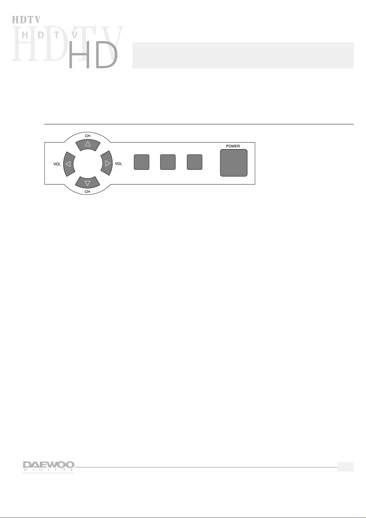
Top panel controls and front panel lights
On the top of the HDTV,you will find the following controls:
1.
VOL (Volume) buttons
Use these buttons to change your HDTV's volume or to move the cursor in the menu screens.
2.
CH (Channel) buttons
Use these buttons to change channels on your HDTV or to move the cursor in the menu screens.
3.
SELECT button
Use this button to select items in the Program Guide and on the menu screens.
4.
MENU button
Use this button to enter and exit the MAIN MENU.Each time you press MENU,the MAIN MENU will
appear and disappear from the screen.
5.
TV/VIDEO button
Use this button to view the equipment you have connected to the HDTV. Each time you press the
TV/VIDEO button,the HDTV will cycle through:
• TV mode
• HD comp (HD Component Video)
• Video 1
• Video 2
• Video 3
• Video 4
6.
POWER button
Use this button to turn your HDTV on or off.
MENU TV/VIDEO MUTE
Introducing your new HDTV
Page 6
2
HDTV
HDTV
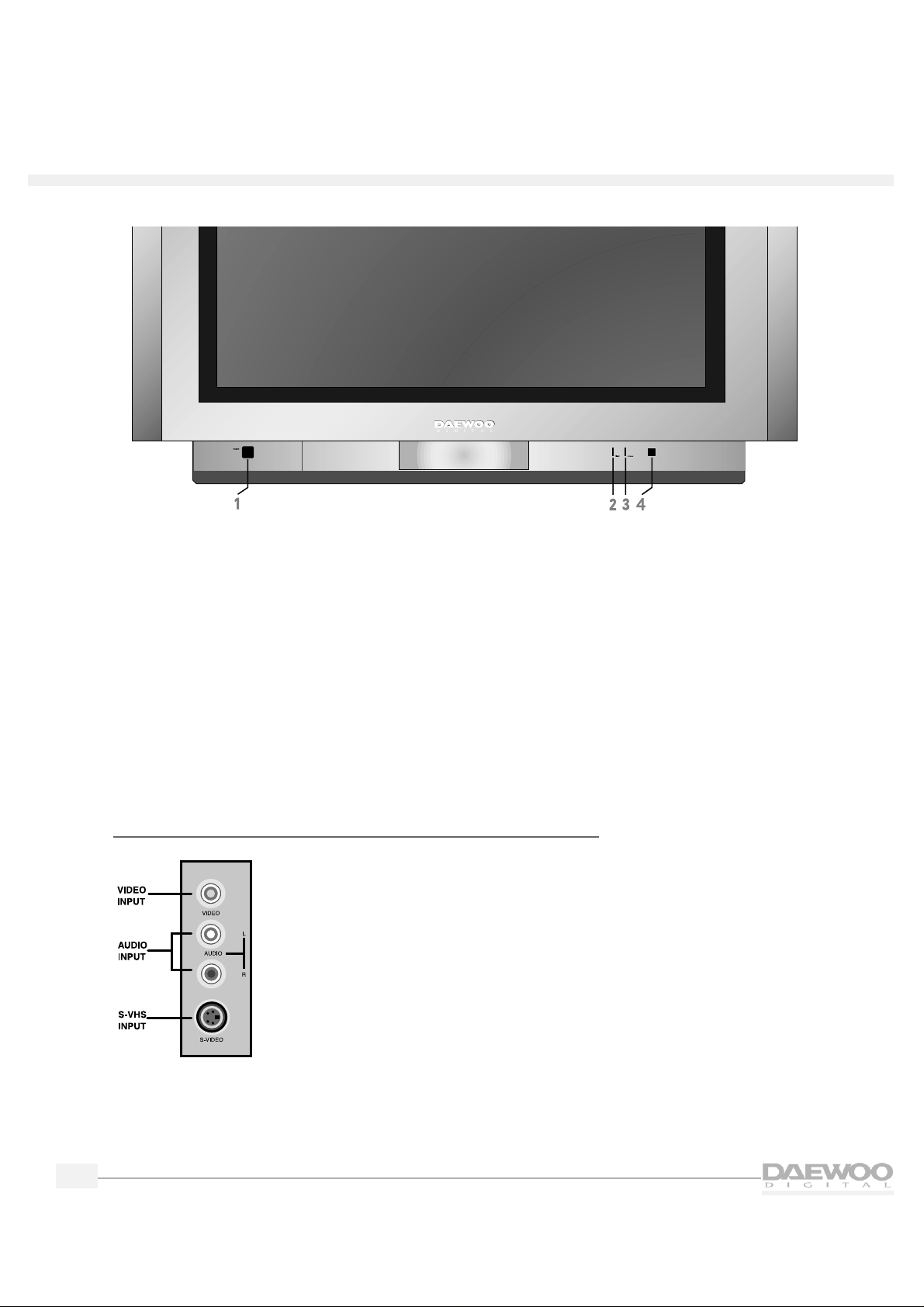
On the front panel of the HDTV,you will find:
1. ON/OFF
2.
Timer Indicator
Lights up red when you have set the HDTV's automatic timers.
3.
Power Indicator
Lights up green when you have turned the HDTV on.
4.
Remote Control Signal Sensor
Receives signals from the remote control.
Side panel inputs
On the right side panel of the HDTV you
will find the Video 4 inputs.These are
provided for connecting a camcorder or
other video equipment without reaching
around to the rear panel.
Page 7
3
HDTV
HDTV
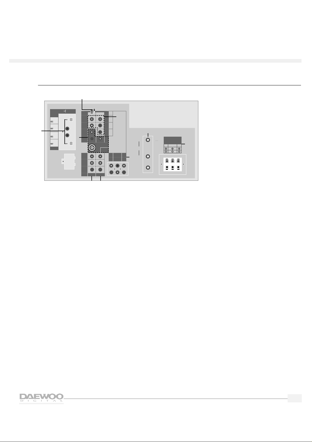
Rear panel inputs and outputs
1.
Digital Audio Inputs and Outputs
Use these inputs and outputs to connect digital audio systems and Digital Video Disc (DVD) players.
Your HDTV provides a choice of either coaxial or optical connections.
2.
SIGNAL SELECT switch
If you connect high definition components,use this switch to select between RGB and Y/Pb/Pr.
Normally,leave this switch in the up (top) position.
3.
High Definition (HD) Component Video Inputs
Use these video inputs to connect special HD components.(1080i or 480P)
4.
VIDEO 1 Inputs
Use to connect video and audio to these inputs.
5.
VIDEO 2 Inputs
Use to connect video and audio to these inputs.
6.
VIDEO 3 Inputs
Use to connect video and audio to these inputs.
7.
HD Component Audio Inputs
Use to connect audio outputs of AC3 audio equipment,such as a DVD,etc.
8.
Antenna Inputs and Outputs
Use to connect antennas (indoor/outdoor/cable) and VCRs to your HDTV.
9.
Speaker Outputs
Use to connect surround speakers and/or a subwoofer to your HDTV.
SPEAKER OUTPUT
L
R
R
R
R
CENTER
WOOFER
LS
RS
VIDEO 2
VIDEO 3
V
V
S-VIDEO
VIDEO 1
B
G
Hs
Vs
INPUT
OUTPUT
DIGITAL AUDIO
VIDEO 1
HD COMPONENT
DO NOT OPEN
(FOR SERVICE ONLY)
SIGNAL SELECT
Y
P
B
PR
HD COMPONENT
VIDEO INPUT
(1080i/480P)
HD COMPONENT
AUDIO INPUT
IN
OUT
CABLE
DTV
IN
VHF
UHF
1
2
3
4
5
6
7
8
9
RS
8‰/5WLS8‰/5W
WOOFER
8‰/8W
(mono)L
(mono)L
OPTICAL
/PCM
OPTICAL
COAXIAL
COAXIAL
/PCM
/PCM
/PCM
Page 8
4
HDTV
HDTV
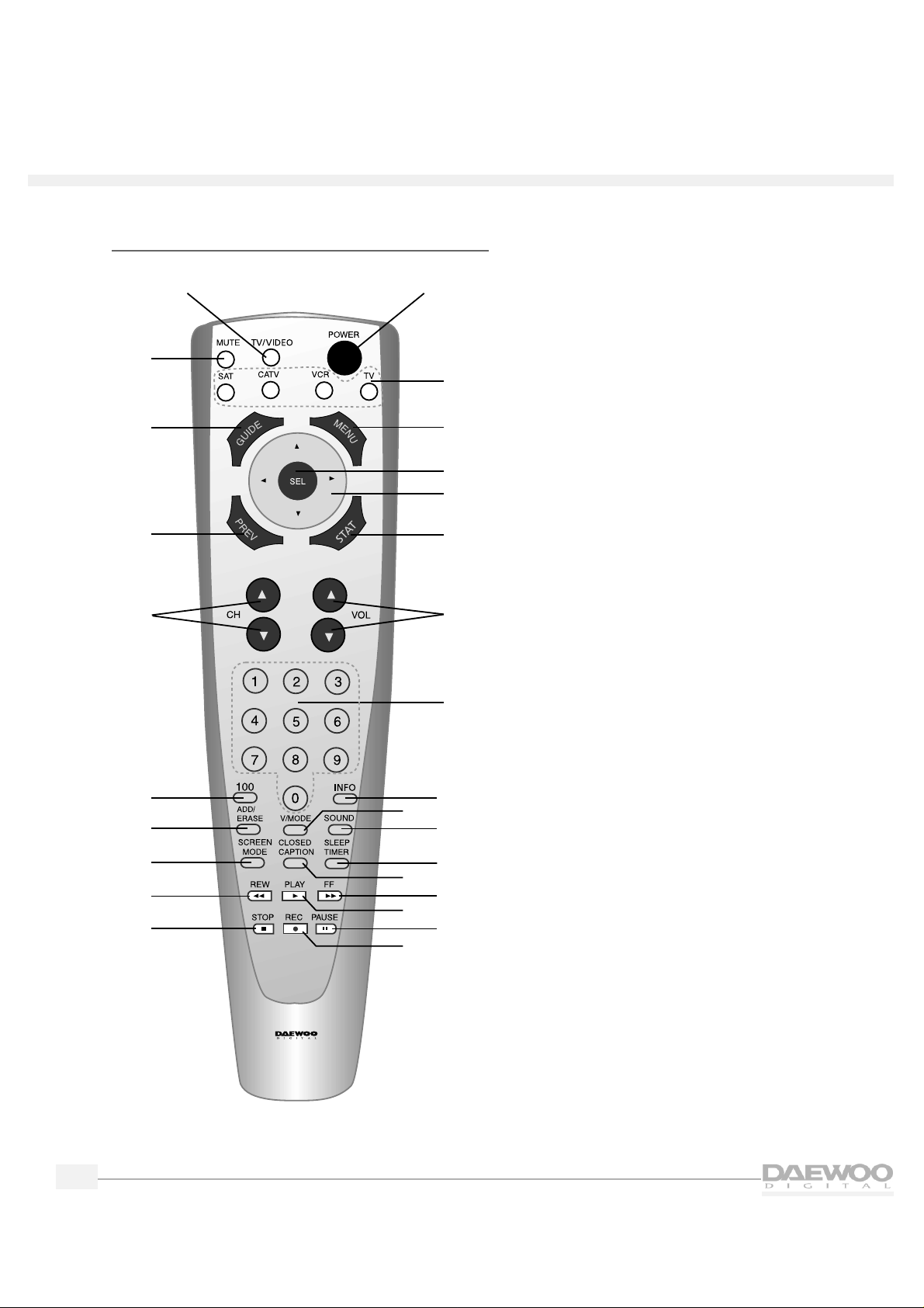
Remote control overview
The remote control has the following functions:
1.
POWER button
Press to turn the HDTV (and other equipment)
on and off.
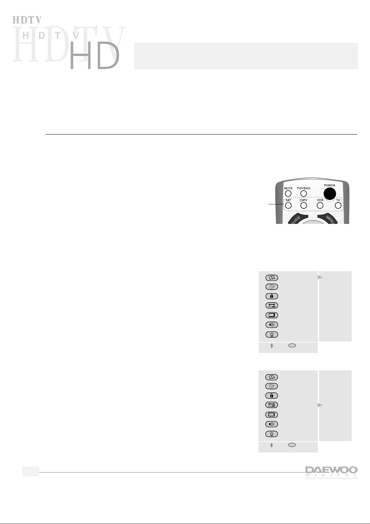
2.
MODE buttons
Press to select which equipment you wish your
remote control to operate:
• SAT (satellite)
• CATV (cable box)
• VCR
•TV
The Mode button you press will light up in red.
3.
MENU button
Press once to display the HDTV menus.Press
again to make the menus disappear.
4.
SEL (Select) button
Press to select items on the HDTV menus.
5.
Arrow buttons
Press to navigate through the HDTV menus.
6.
STAT (Channel Station) button
Press to quickly select channels to watch on
your HDTV.
7.
VOL (Volume) buttons
Press to raise and lower the volume on y our HDTV.
8.
Number buttons
Press to directly select channels or to enter the
numbers in the menus.
9.
INFO (Information) button
Press to see the channel banner that provides
information while viewing your HDTV.
10.
V MODE (Video Mode) button
Press to select a video mode:Normal,Dynamic,
Cinema or Customer.
26
27
1
2
3
4
5
6
7
8
9
10
11
12
13
14
15
16
17
18
19
20
21
22
23
24
25
R-V3
Page 9

5
HDTV
HDTV
11.
SOUND button
Press to select a sound option:Mono,Stereo,or
Secondary Audio Programming (SAP).When
you tune to a digital channel,press to select
various languages.
12.
SLEEP TIMER button
Press to select the time before the HDTV turns
off:30 minutes,60 minutes, 90 minutes,or 120
minutes.
13.
CLOSED CAPTION button
Press to turn closed captions on and off.
14.
FF (Fast Forward) button
Press to fast forward a videocassette.
15.
PLAY button
Press to play a videocassette.
16.
PAUSE button
Press to pause a VCR.
17.
REC (Record) button
Press to record a videotape.
18.
STOP button
Press to stop a VCR.
19.
REW (Rewind) button
Press to rewind a videocassette.
20.
SCREEN MODE button
Press to select how to view your HDTV:
Normal,Full or Zoom.
21.
ADD/ERASE button
Press to add and erase channels on your HDTV.
22.
100 button
Press to select cable channels over 100 on TV
or DSS broadcasts.
23.
CH (Channel) buttons
Press to select channels.
24.
PREV (Previous) button
Press to back up one menu at a time in the
HDTV menus or to return to the previous
channel.
25.
GUIDE button
Press this button to see the HDTV Program
Guide.
26.
MUTE button
Press to mute the HDTV sound.
27.
TV/VIDEO button
Press to view components you have connected
to the HDTV.Press this button repeatedly to
display:
• TV mode
• HD comp (HD Component Video)
• Video 1
• Video 2
• Video 3
• Video 4
Page 10
6
HDTV
HDTV
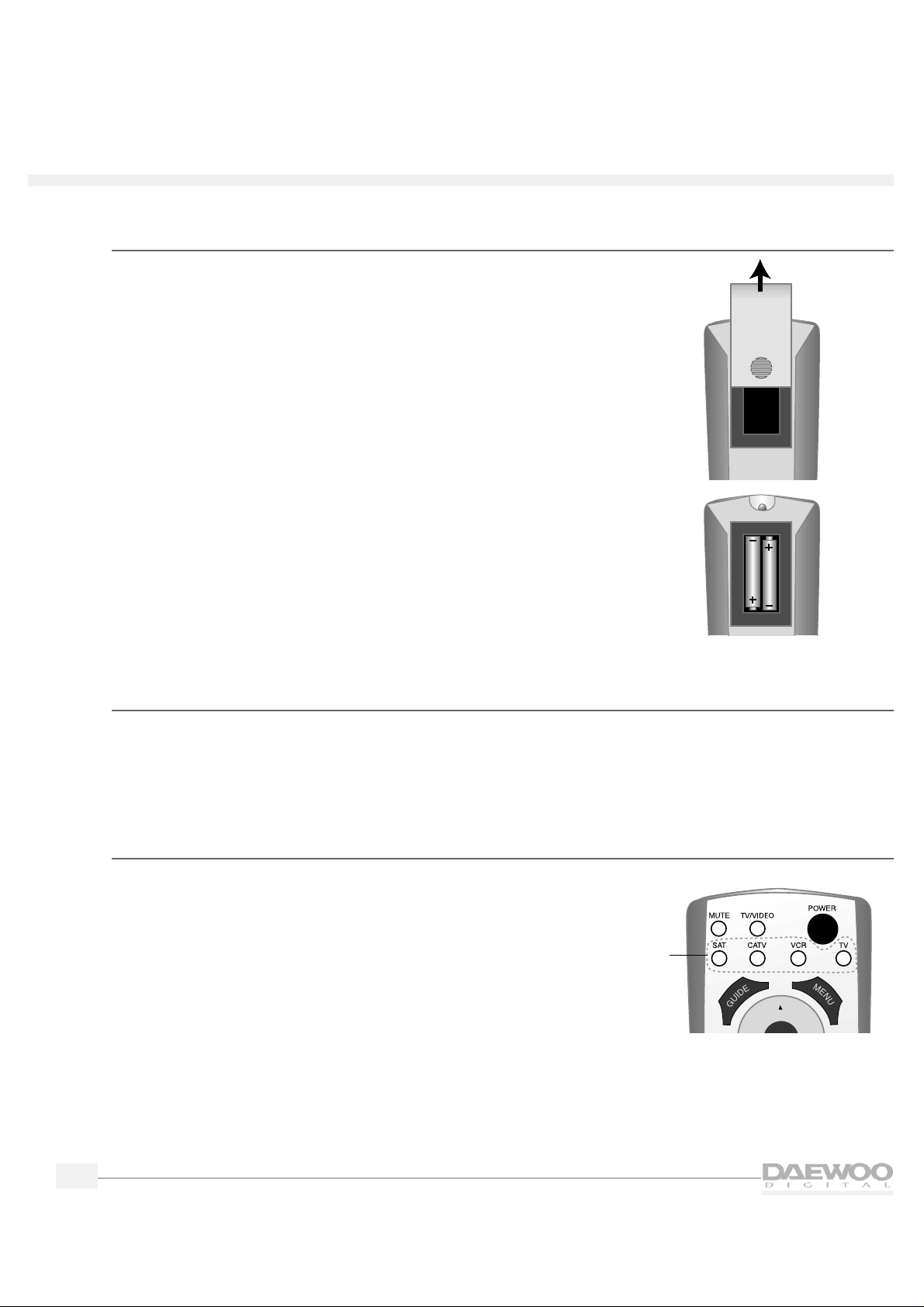
Installing the batteries in the remote control
1.
Remove the battery compartment lid from the back of the
remote control by pressing on the lid and sliding it off.
2.
Insert two AAA batteries into the compartment.Match the +
and — on the batteries to the + and — in the compartment.
3.
Replace the battery cover.
Programming the remote control
The HDTV remote control is pre-programmed to operate your Daewoo HDTV.You can also program the
HDTV remote control to operate other components,such as a cable TV box, a DSS,or a VCR.To program
the HDTV remote control,please see "Programming the Remote Control”on page 40.
Operating the remote control
Whenever you use the remote,you must first press the Mode
button on the remote control to select the equipment you wish to
control.For example,to control the HDTV, press the TV Mode
button.The button will light up red.
Mode
buttons
Page 11
7
Connecting your HDT V
CAUTION - Make sure your HDTV is unplugged before connecting equipment.
This chapter explains how to connect all of your equipment to the HDTV.Before you begin,Daewoo
suggests you make sure you have all of the cables and wires you will need.These may include:
• Speaker wire
• Coaxial cable (for VCRs, DVDs,etc.)
• RCA pin type audio/video cables
• Super Video cables (for S-Video equipment)
• Optical Digital cables (for special audio connections)
• 75 ohm adapter or combiner (for antennas)
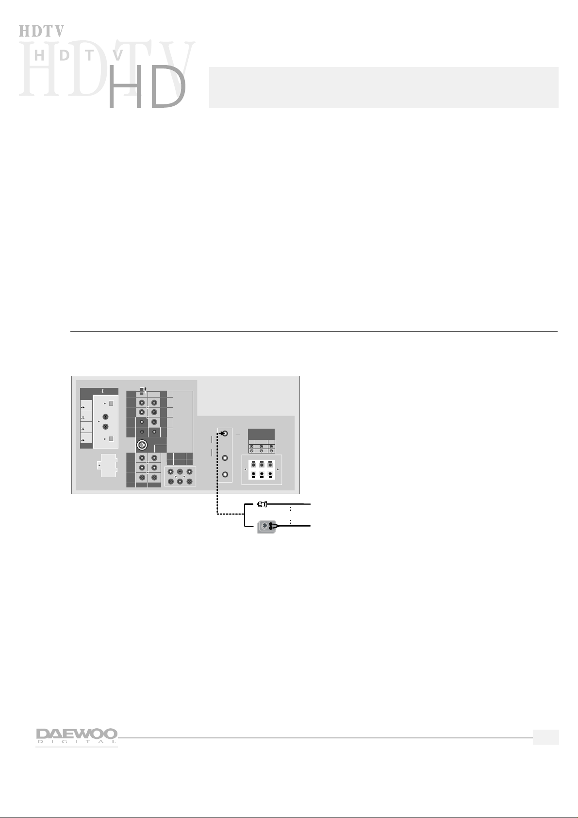
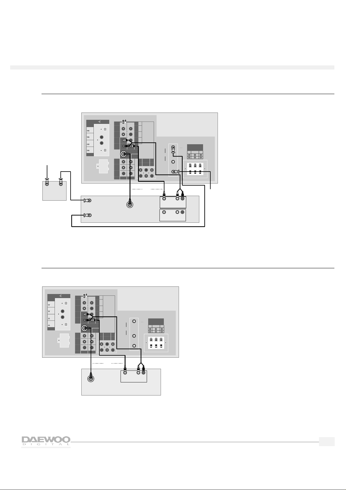
Indoor/outdoor antenna
To connect an indoor/outdoor antenna follow the diagram below.You may need a 75-ohm adapter,
as shown.
SPEAKER OUTPUT
L
R
R
R
R
CENTER
WOOFER
LS
RS
VIDEO 2
VIDEO 3
V
V
S-VIDEO
VIDEO 1
B
G
Hs
Vs
INPUT
OUTPUT
DIGITAL AUDIO
VIDEO 1
HD COMPONENT
DO NOT OPEN
(FOR SERVICE ONLY)
SIGNAL SELECT
Y
P
B
PR
HD COMPONENT
VIDEO INPUT
(1080i/480P)
HD COMPONENT
AUDIO INPUT
IN
OUT
CABLE
DTV
IN
From
Antenna
Source
OR
VHF
UHF
Adapter
RS
8‰/5WLS8‰/5W
WOOFER
8‰/8W
(mono)L
(mono)L
OPTICAL
/PCM
OPTICAL
COAXIAL
COAXIAL
/PCM
/PCM
/PCM
Page 12
8
HDTV
HDTV
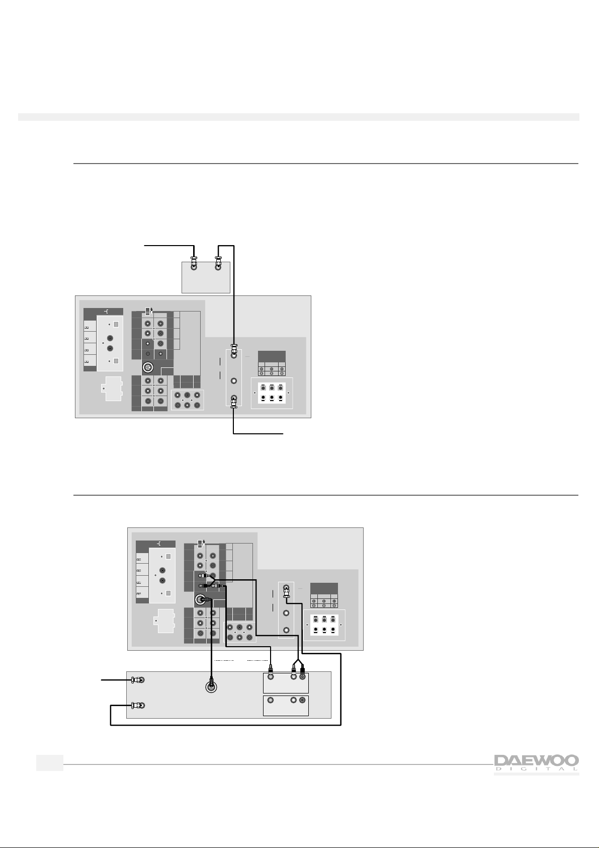
Indoor/outdoor antenna and cable TV
If you have a cable box,plug the cable from the wall into the IN terminal of the cable box.Connect a
coaxial cable between the OUT terminal of the cable box and the antenna input on the HDTV labeled IN.
If you wish to connect a VCR with your cable box,please see “VCR With a Cable Box”on page 9.
❑ NOTE: It is necessary to connect an indoor/outdoor antenna to receive digital broadcasts.
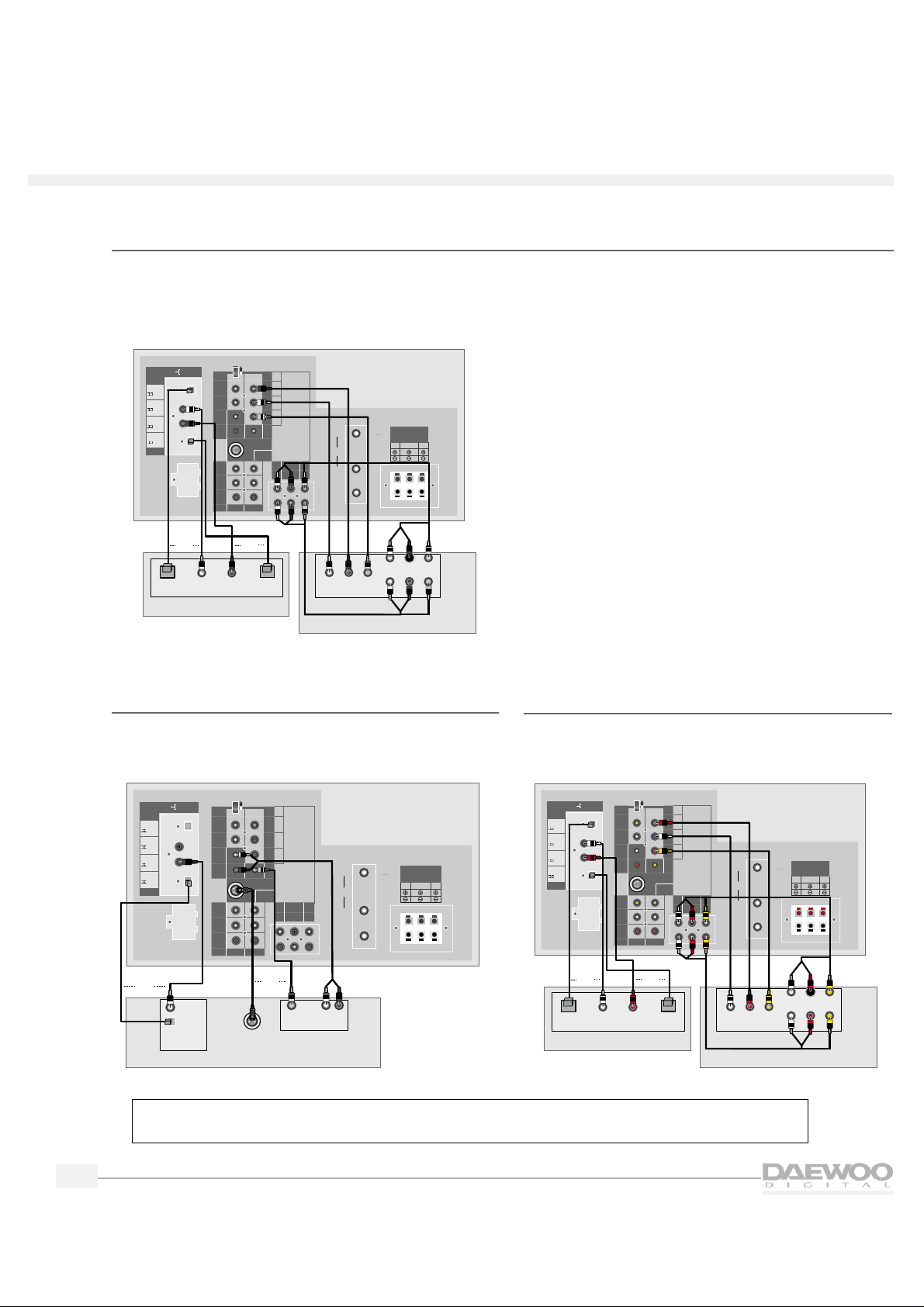
VCR without a cable box
To connect a VCR to your HDTV without using a cable box,follow the diagram below.
If you are connecting a mono VCR, connect only the L/MONO.
SPEAKER OUTPUT
L
R
R
R
R
CENTER
WOOFER
LS
RS
VIDEO 2
VIDEO 3
V
V
S-VIDEO
VIDEO 1
B
G
Hs
Vs
INPUT
OUTPUT
DIGITAL AUDIO
VIDEO 1
HD COMPONENT
DO NOT OPEN
(FOR SERVICE ONLY)
SIGNAL SELECT
Y
P
B
PR
HD COMPONENT
VIDEO INPUT
(1080i/480P)
HD COMPONENT
AUDIO INPUT
IN
OUT
CABLE
DTV
IN
From
Antenna
Source
VCR
In From Antenna
Out to TV
Out
In
S-VIDEO
L
R
Video
Audio
Video
Audio
OR
L
R
VHF
UHF
RS
8‰/5WLS8‰/5W
WOOFER
8‰/8W
(mono)L
(mono)L
OPTICAL
/PCM
OPTICAL
COAXIAL
COAXIAL
/PCM
/PCM
/PCM
SPEAKER OUTPUT
L
R
R
R
R
CENTER
WOOFER
LS
RS
VIDEO 2
VIDEO 3
V
V
S-VIDEO
VIDEO 1
B
G
Hs
Vs
INPUT
OUTPUT
DIGITAL AUDIO
VIDEO 1
HD COMPONENT
DO NOT OPEN
(FOR SERVICE ONLY)
SIGNAL SELECT
Y
P
B
PR
HD COMPONENT
VIDEO INPUT
(1080i/480P)
HD COMPONENT
AUDIO INPUT
IN
OUT
CABLE
DTV
IN
From
Cable
Source
Optional
Cable Box
In
Out
From
Antenna
Source
VHF
UHF
OPTICAL
/PCM
OPTICAL
COAXIAL
COAXIAL
/PCM
/PCM
/PCM
(mono)L
(mono)L
RS
8‰/5WLS8‰/5W
WOOFER
8‰/8W
Page 13
9
HDTV
HDTV
VCR with a cable box
To connect a VCR with a cable box,follow the diagram below.
If you are connecting a mono VCR, connect only L/MONO.
Digital Satellite System (DSS) or Laser Disc (LD)
To connect a Digital Satellite System or Laser Disc,follow the diagram below.
SPEAKER OUTPUT
L
R
R
R
R
CENTER
WOOFER
LS
RS
VIDEO 2
VIDEO 3
V
V
S-VIDEO
VIDEO 1
B
G
Hs
Vs
INPUT
OUTPUT
DIGITAL AUDIO
VIDEO 1
HD COMPONENT
DO NOT OPEN
(FOR SERVICE ONLY)
SIGNAL SELECT
Y
P
B
PR
HD COMPONENT
VIDEO INPUT
(1080i/480P)
HD COMPONENT
AUDIO INPUT
IN
OUT
CABLE
DTV
IN
Satellite Receiver or Laser Disc
Out
S-VIDEO
L
R
Video
Audio
OR
VHF
UHF
OPTICAL
/PCM
OPTICAL
COAXIAL
COAXIAL
/PCM
/PCM
/PCM
(mono)L
(mono)L
RS
8‰/5WLS8‰/5W
WOOFER
8‰/8W
SPEAKER OUTPUT
L
R
R
R
R
CENTER
WOOFER
LS
RS
VIDEO 2
VIDEO 3
V
V
S-VIDEO
VIDEO 1
B
G
Hs
Vs
INPUT
OUTPUT
DIGITAL AUDIO
VIDEO 1
HD COMPONENT
DO NOT OPEN
(FOR SERVICE ONLY)
SIGNAL SELECT
Y
P
B
PR
HD COMPONENT
VIDEO INPUT
(1080i/480P)
HD COMPONENT
AUDIO INPUT
IN
OUT
CABLE
DTV
IN
VCR
In From Antenna
Out to TV
Out
In
S-VIDEO
L
R
Video
Audio
Video
Audio
OR
From
Cable
Source
In
Out
L
R
Optional
Cable Box
From
Antenna
Source
VHF
UHF
OPTICAL
/PCM
OPTICAL
COAXIAL
COAXIAL
/PCM
/PCM
/PCM
(mono)L
(mono)L
RS
8‰/5WLS8‰/5W
WOOFER
8‰/8W
Page 14
10
HDTV
HDTV
HD component and audio system
To connect a HD component and audio system,follow the diagram below.
❑ NOTE: After you connect a digital audio system, you will need to use the menus to set it up. Please see
“Setting up Digital Audio” on page 22.
DVD (480i)
To connect a digital video disc (DVD),follow the
diagram below.
SPEAKER OUTPUT
L
R
R
R
R
CENTER
WOOFER
LS
RS
VIDEO 2
VIDEO 3
V
V
S-VIDEO
VIDEO 1
B
G
Hs
Vs
INPUT
OUTPUT
DIGITAL AUDIO
VIDEO 1
HD COMPONENT
DO NOT OPEN
(FOR SERVICE ONLY)
SIGNAL SELECT
Y
P
B
PR
HD COMPONENT
VIDEO INPUT
(1080i/480P)
HD COMPONENT
AUDIO INPUT
IN
OUT
CABLE
DTV
IN
Digital Video Disc
S-VIDEO
Out
L
R
Video
Audio
OR
Out
Optical
Digital Audio
Coaxial
OR
VHF
UHF
RS
8‰/5WLS8‰/5W
WOOFER
8‰/8W
(mono)L
(mono)L
OPTICAL
/PCM
OPTICAL
COAXIAL
COAXIAL
/PCM
/PCM
/PCM
SPEAKER OUTPUT
L
R
R
R
R
CENTER
WOOFER
LS
RS
VIDEO 2 VIDEO 3
V
V
S-VIDEO
VIDEO 1
B
G
Hs
Vs
INPUT
OUTPUT
DIGITAL AUDIO
VIDEO 1
HD COMPONENT
DO NOT OPEN
(FOR SERVICE ONLY)
SIGNAL SELECT
Y
P
B
PR
HD COMPONENT
VIDEO INPUT
(1080i/480P)
HD COMPONENT
AUDIO INPUT
IN
OUT
CABLE
DTV
IN
HD Component
Audio
L
Center
SL
Out
R
Woofer
SR
Optical
In
Coaxial
In
Optical
Out
Coaxial
Out
Digital Audio System
PB Y
PR
OR
OR
VHF
UHF
OPTICAL
/PCM
OPTICAL
COAXIAL
COAXIAL
/PCM
/PCM
/PCM
(mono)L
(mono)L
RS
8‰/5WLS8‰/5W
WOOFER
8‰/8W
DVD (480P)
To connect a digital video disc (DVD),follow the
diagram below.
SPEAKER OUTPUT
L
R
R
R
R
CENTER
WOOFER
LS
RS
VIDEO 2
VIDEO 3
V
V
S-VIDEO
VIDEO 1
B
G
Hs
Vs
INPUT
OUTPUT
DIGITAL AUDIO
VIDEO 1
HD COMPONENT
DO NOT OPEN
(FOR SERVICE ONLY)
SIGNAL SELECT
Y
P
B
PR
HD COMPONENT
VIDEO INPUT
(1080i/480P)
HD COMPONENT
AUDIO INPUT
IN
OUT
CABLE
DTV
IN
Digital Video Disc
Audio
L
Center
SL
Out
R
Woofer
SR
Optical
In
Coaxial
In
Optical
Out
Coaxial
Out
Digital Audio System
Cb Y
Cr
OR
OR
VHF
UHF
OPTICAL
/PCM
OPTICAL
COAXIAL
COAXIAL
/PCM
/PCM
/PCM
(mono)L
(mono)L
RS
8‰/5WLS8‰/5W
WOOFER
8‰/8W
❑ NOTE: After you connect a HD component, you will need to use the menus to set it up.
Please see “Setting up HD Components Video” on page 20.
Page 15
11
HDTV
HDTV
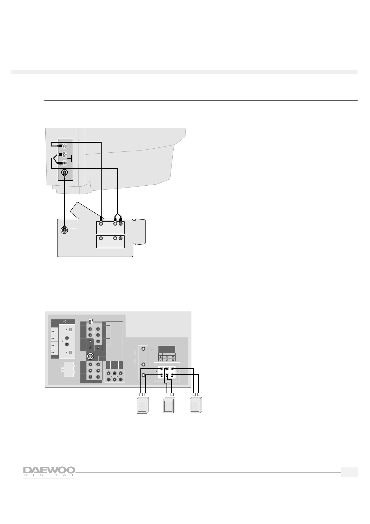
Camcorder
The Video 4 inputs on the side of the HDTV make it easy to connect a camcorder.To do this,follow the
diagram below.
Speakers
To connect standard speakers,follow the diagram below.
SPEAKER OUTPUT
L
R
R
R
R
CENTER
WOOFER
LS
RS
VIDEO 2
VIDEO 3
V
V
S-VIDEO
VIDEO 1
B
G
Hs
Vs
INPUT
OUTPUT
DIGITAL AUDIO
VIDEO 1
HD COMPONENT
DO NOT OPEN
(FOR SERVICE ONLY)
SIGNAL SELECT
Y
P
B
PR
HD COMPONENT
VIDEO INPUT
(1080i/480P)
HD COMPONENT
AUDIO INPUT
IN
OUT
CABLE
DTV
IN
Right Rear
Speaker
+
_
Left Rear
Speaker
Subwoofer
+
_
+
_
VHF
UHF
RS
8‰/5WLS8‰/5W
WOOFER
8‰/8W
(mono)L
(mono)L
OPTICAL
/PCM
OPTICAL
COAXIAL
COAXIAL
/PCM
/PCM
/PCM
VIDEO
AUDIO
R
L
Camcorder
Out
In
S-VIDEO
L
R
Video
Audio
Video
Audio
OR
L
R
Side of HDTV
S-VIDEO
Page 16
This chapter explains the basic setup required for watching and listening to your HDTV for the first time.
Daewoo has made setup as easy as possible with the use of on-screen menus and simple navigation controls.
Using the on-screen menu system
Daewoo has designed an easy-to-use menu system for controlling your television. Along with your remote
control,the menus make all of your HDTV's controls and features a few button presses away.
To use the menus:
1.
Press the TV Mode button on the remote control.
The TV indicator will light.
2.
Point the remote control at the HDTV and press POWER.
The POWER indicator on the front of the HDTV will light
from red to green and the HDTV will turn on.
3.
Press the MENU button.
The MAIN MENU will appear on the screen.
4.
Press the up/down arrow buttons to highlight items on the
MAIN MENU.
The content of each menu category will be displayed.
5.
Press the SEL button to select an item.
6.
Press the PREV button to back up one menu screen.
7.
To make the menus disappear,press MENU repeatedly.
12
Setting up your HDT V
Mode
buttons
Move
MAIN MENU
GUIDE
PREFERENCE
LOCKS & LIMITS
SETUP
VIDEO
AUDIO
HELP
The Guide Menu
allows you to
view and select
the program
information
SEL
Select
Move
MAIN MENU
GUIDE
PREFERENCE
LOCKS & LIMITS
SETUP
VIDEO
AUDIO
HELP
Input Select
Channel Setup
Time Setting
Digital Audio
Speaker Setup
Factory Setting
HD Comp.
SEL
Select
Page 17

13
HDTV
HDTV
Setting the time and date
1.
Press the MENU button to display the MAIN MENU.
2.
Press the up/down arrow buttons to highlight SETUP.
3.
Press the SEL button.
The SETUP menu is displayed.
4.
Use the up/down arrow buttons to highlight Time Setting.
Press the SEL button.
The TIME SETUP menu is displayed,with the Time and Date
Setting highlighted.
5.
Press the SEL button.
The TIME SETTING menu is displayed.
❑ NOTE: If your HDTV is receiving digital signals, the time
will automatically be set and updated.
SETUP
• Input Select
• Channel Setup
• Time Setting
• Digital Audio
• Speaker Setup
• Factory Setting
• HD Component Input
Select one of the
setup options.
Move
SEL
Select
TIME
SETUP
• Time and Date Setting
• Time Options
Select an option
to set the time.
After completing,
press the SEL
button.
Move
SEL
Select
TIME
SETTING
Set the time,
date, year using
the Number
button.
After completing,
press the SEL
button.
Time:
Date:
Year
:
1
2
0
0
A
/
0
1
0
0
2 0
0
0
Move Number
#
Move
MAIN MENU
GUIDE
PREFERENCE
LOCKS & LIMITS
SETUP
VIDEO
AUDIO
HELP
Input Select
Channel Setup
Time Setting
Digital Audio
Speaker Setup
Factory Setting
HD Comp.
SEL
Select
Page 18

14
HDTV
HDTV
6.
Use the Number (0-9) buttons on the remote control to enter
the time.For example,to enter 12:45 press 1,2,4,and 5.
7.
Use the up/down arrow buttons to select A (AM) or P (PM)
then press the right arrow button to move to the Date field.
8.
Use the Number buttons to enter the Date and Year and then
press the SEL button to return to the TIME SETUP menu.
9.
Use the up/down arrow buttons to highlight Time Options
and then press the SEL button.
The TIME OPTIONS menu is displayed.
10.
Use the up/down arrow buttons to highlight your time zone
and then press the SEL button.
11.
Use the up/down arrow buttons to select whether you use
daylight saving time and then press the SEL button.
12.
Press the PREV button to return to the SETUP menu.
Memorizing channels
Your HDTV memorizes and stores all of the channels it can receive.
❑ NOTE: It is not necessary to scan channels into memory for satellite or VCR input sources.
To scan channels into memory:
1.
From the SETUP menu,use the up/down arrow buttons to
highlight Input Select and press the SEL button.
The INPUT SELECT menu is displayed.
2.
Use the up/down arrow buttons to highlight the kind of
antenna you connected to the HDTV: Antenna
(indoor/outdoor) or Antenna + Cable (cable TV and
indoor/outdoor).Press the SEL button.
TIME
SETTING
Set the time,
date, year using
the Number
button.
After completing
press the SEL
button.
Time:
Date:
Year
:
1
2
4
5
P
/
0
1
0 1
2 0
0
0
Move Number
#
TIME
OPTIONS
Select a time
zone & daylight
saving on/off.
Select your Time Zone
• Eastern
• Central
• Mountain
• Pacific
• Alaska
• Hawaii
Daylight Saving Time Control
• Off
• On
Move
SEL
Select
INPUT
SELECT
• Antenna
• Antenna + Cable
If you use the
cable TV, select
Antenna + Cable.
Move
SEL
Select
Page 19

15
HDTV
HDTV
3.
Press the PREV button to return to the SETUP menu.
4.
Use the up/down arrow buttons to highlight Channel Setup
and then press the SEL button.
The CHANNEL SETUP menu is displayed.
5.
Use the up/down arrow buttons to highlight Channel
Scanning and then press the SEL button.
The CHANNEL SCANNING menu is displayed.
To scan the channels into the HDTV memory
• If Yes is highlighted,press the SEL button to begin channel
scanning.
• If No is highlighted,use the up/down ar row buttons to
highlight Yes and then press SEL to begin channel scanning.
The HDTV will scan the channels and memorize all channels it
can receive.
When the channel scan is finished,press the MENU button
until the menus disappear from the screen,or press the PREV
button to select another menu option.
To exit the menu without scanning the channels
• If Yes is highlighted,use the up/down arrow buttons to
highlight No and then press the SEL button to return to the
previous menu.
• If No is highlighted,press the SEL button to return to the
previous menu.
❑ NOTE: Whenever you change the input source (Antenna or
Antenna + Cable) from the INPUT SELECT menu, you
should scan the channels again.
CHANNEL
SETUP
• Check Signal Strength
• Channel Scanning
• Add/Erase Channel
• Fine Tuning
Select one of the
channel options.
Move
SEL
Select
CHANNEL
SCANNING
This function will rescan channel and update
your channel map.
• Yes • No
Start channel scan
Move
SEL
Select
CHANNEL
SCANNING
This function will rescan channel and update
your channel map.
• Yes • No
Channel scanning.... #CH22
28%
Move
SEL
Select
Page 20

16
HDTV
HDTV
Adding/erasing channels
You can easily add or erase channels that your HDTV memorized.
To do this:
1.
From the MAIN MENU highlight SETUP and press the SEL button.
2.
Highlight Channel Setup and press the SEL button.
3.
Highlight Add/Erase Channel.Press the SEL button.
4.
You will see a screen that asks you whether you wish to add
or erase a channel.If you want to add/erase a channel,press
the SEL button after highlighting Yes.
5.
You will see the pop-up menu.
• If a channel is memor ized, the menu asks you whether
you wish to erase it or not.
Press the SEL button after highlighting Yes if you want to
erase a channel.
• If a channel is not memor ized, the menu asks you
whether you wish to add it or not.
Press the SEL button after highlighting Yes if you want to
add a channel.
When finished,press the MENU button until the menus
disappear from the screen,or press the PREV button to select
another menu option.
6.
You can also use the ADD/ERASE button on your remote
control to add/erase channels.After selecting the channel to
add or erase using the Number buttons,press the ADD/ERASE
button on your remote control.You will see the pop-up menu.
• If a channel is memor ized, the menu asks you whether
you wish to erase it or not.Press the SEL button after
highlighting Yes if you want to erase a channel.
• If a channel is not memor ized, the menu asks you
whether you wish to add or not.Press the SEL button after
highlighting Yes if you want to add a channel.
SETUP
• Input Select
• Channel Setup
• Time Setting
• Digital Audio
• Speaker Setup
• Factory Setting
• HD Component Input
Select one of the
setup options.
Move
SEL
Select
CHANNEL
SETUP
• Check Signal Strength
• Channel Scanning
• Add/Erase Channel
• Fine Tuning
Select one of the
channel options.
Move
SEL
Select
ADD/ERASE
CHANNEL
Do you want to add/erase this channel?
• Yes • No
• Yes • No
Do you want to erase
current channel in your
channel map?
You can add the
new channel or
erase unwanted
channel.
Move
SEL
Select
Page 21

17
HDTV
HDTV
Fine tuning channels
You can fine tune channels that do not appear as clearly as they should.
❑ NOTE: You cannot fine tune a digital channel. Digital channels
either appear perfectly tuned or they do not appear at all.
To fine tune a channel:
1.
From the CHANNEL SETUP menu use the up/down arrow
buttons to highlight Fine Tuning.Press the SEL button.You will
see the FINE TUNING menu.
2.
Press the left/right arrow buttons to fine tune the channel and
you will see the numeric values on the bar change.The
maximum is +48 and the minimum is -48.Keep pressing the
left/right arrow buttons until the channel is as clear as
possible.
3.
To fine tune another channel,fir st, select the channel then
repeat steps 1-2 above.When finished, press the MENU button
until the menus disappear from the screen,or press the PREV
button to select another menu option.
Checking signal strength
You can check and see how strong a channel is tuned in.
❑ NOTE: This does not apply to analog stations.
To check signal strength:
1.
From the CHANNEL SETUP menu use the up/down arrow
buttons to highlight Check Signal Strength.Press the SEL
button.You will see the SIGNAL STRENGTH menu.
2.
The menu will show the channel you are tuned to,and a
numeric value of its signal strength.You will also see a meter
that shows if the signal is weak,acceptable,or excellent.
3.
Adjust your indoor/outdoor antenna until the signal strength is
as good as possible.When finished press the MENU button
until the menus disappear from the screen,or press the PREV
button to select another menu option.
CHANNEL
SETUP
• Check Signal Strength
• Channel Scanning
• Add/Erase Channel
• Fine Tuning
Select one of the
channel options.
Move
SEL
Select
SIGNAL
STRENGTH
Adjust the antenna for optimum signal
strength
Signal Strength: 82
Channel Number: 11
Weak Acceptable Excellent
Check the signal
strength.
FINE
TUNING
Notice: You can not fine tune the digital
signals.
• Fine Tuning
0
If analog
channels are not
clear, you can
fine tune signals
for a better
picture.
Control
Page 22

18
HDTV
HDTV
Selecting channels
Daewoo has provided a number of different ways to conveniently select channels.They include:
• Using the Channel buttons
• Using the Number buttons
• Using the channel selector
• Selecting favorite channels
❑ NOTE: To change digital channels from the Program Guide, please see “Using the Program Guide” on
page 25.
Using the Channel buttons
To change channels,press the up/down CH buttons on the remote
control or top panel of the HDTV.
Using the Number buttons
To directly select a channel between 1-99,press its two-digit
number with the Number buttons.If the channel is 100 and above,
press the 100 button first,then the additional two digits.For
example,if the channel is 114,press the 100 button then 1, then 4.
Using the Channel Station (STAT) button
Daewoo's convenient Channel Station button lets you see a
channel map of all of your memorized stations.You can use this
map to directly select a channel.
To use this feature:
1.
Press the STAT button on the remote control.You will see a
channel map screen,with an arrow to indicate if there are
more channels that are stored.The channel you are tuned to
appears in red.
2.
Use the arrow buttons to highlight a channel.You can use
either up/down arrow or left/right arrow.To see more
channels that are stored,simply keep pressing arrow down
until the other channels appear.
3.
Press the SEL button to directly tune to a channel in your
channel map.
481011
13 15 16 18
25 29 34 59
Page 23

19
HDTV
HDTV
Selecting favorite channels
Your HDTV can store up to 16 channels that you can quickly
select by using the arrow buttons on the remote controls.To store
and select your favorite channels:
1.
From the MAIN MENU,use the up/down arrow buttons to
highlight PREFERENCE.Press the SEL button to see the
PREFERENCE menu.
2.
Use the up/down arrow buttons to highlight Favorite Channel.
Press the SEL button to see the FAVORITE CHANNEL menu.
3.
To select your favorite channels,use the arrow buttons to
highlight a channel to add to your list.Press the SEL button to
add channels.The channel number will be highlighted and the
number will appear at the top.
4.
To delete a channel from the list,simply highlight the channel
again and press the SEL button.It will be deleted and the
channel number will disappear from the top of the menu.
When finished,press the MENU button until the menus
disappear from the screen.
To select favorite channels while viewing your HDTV,simply
press the up/down arrow buttons on the remote control.You
will cycle through all of the channels on your favorite channel list.
PREFERENCE
• Favorite Channels
• OSD Screen Color
• Closed Caption
• On/Off Timer
Select one of the
preference
options.
Move
SEL
Select
FAVORITE
CHANNEL
Choose favorite
channels. If you
want to delete,
select again.
Move
SEL
Select
You can select up to 16 channels.
891011
12 13 16 17
22 29 34 40
51 53 59 61
FAVORITE
CHANNEL
Choose favorite
channels. If you
want to delete,
select again.
Move
SEL
Select
You can select up to 16 channels.
8 9 16 34
891011
12 13 16 17
22 29 34 40
51 53 59 61
Page 24

20
HDTV
HDTV
Selecting a source
You can choose to view any of the input sources that you have connected to your HDTV.
To do this:
Press the TV/VIDEO button on the HDTV or on the remote
control.
Each time you press either button,the HDTV will display one
of the sources that are available.These include:
• TV mode
• HD comp (HD Component Video)
• Video 1
• Video 2
• Video 3
• Video 4
These sources correspond to the inputs on the side and back panel of the HDTV.For example,if you
connected a VCR to the Video 2 inputs,use the TV/VIDEO button on the HDTV or on the remote
control to select Video 2 and to see the picture and hear the audio from the VCR.
Setting up HD Components Video
You can select the input format of the HD Components Video.
1.
From the MAIN MENU,use the up/down buttons to highlight
SETUP and press the SEL button.
The SETUP menu is displayed.
2.
Use the up/down buttons to highlight HD Component Input
and press the SEL button.
The HD Component Input menu is displayed.
3.
Highlight the item you want to set using the up/down buttons.
4.
Press the SEL button.
5.
Press the PREV or MENU button to exit this menu.
Setting up speakers
You can easily adjust the HDTV to the kind of speakers you
connected to it.
1.
From the MAIN MENU,use the up/down arrow buttons to
highlight SETUP and press the SEL button.
The SETUP menu is displayed.
2.
Use the up/down arrow buttons to highlight Speaker Setup
and press the SEL button.
The SPEAKER SETUP menu is displayed.
VIDEO 1
SPEAKER
SETUP
• Rear Speakers (LS, RS)
• Subwoofer
• Speakers Off
Select the kind of
speakers to set.
Move
SEL
Select
HD Comp.
• 1080i
• 480P
Select the input
format of the
HD components.
Move
SEL
Select
Page 25

3
. Press the up/down arrow buttons to highlight Speaker Off and
press the SEL button.
The SPEAKER OFF menu is displayed.
4.
If you:
• do not want to use external (left/right/center) speakers,
highlight No and press the SEL button.
• do want to use external speakers,highlight Yes and press
the SEL button.
5.
Press the PREV button to return to the SPEAKER SETUP menu.
Adjusting rear speakers for surround sound
1.
From the SPEAKER SETUP menu,highlight Rear Speakers
(LS,RS) and press the SEL button.
The REAR SPEAKERS menu is displayed.
2.
Highlight the kind of rear speakers you connected to the
HDTV:
• External (Large)
• External (Small)
• None
3.
Press the SEL button.
4.
Press the PREV button to return to the SPEAKER SETUP menu.
To adjust for a subwoofer:
1.
From the SPEAKER SETUP menu,highlight Subwoofer.Press
the SEL button.
2.
If you:
• do not want to use a subwoofer,highlight No and press
the SEL button
• do want to use a subwoofer,highlight Yes and press the
SEL button.
When finished,press the PREV button to return to the
SPEAKER SETUP menu.
21
HDTV
HDTV
REAR
SPEAKER
Select the type
of rear speaker
connected to
the HDTV.
Move
SEL
Select
• External (Large)
• External (Small)
• None
SPEAKER OFF
If you want to
use the external
L/R/C speakers,
select 'Yes'.
Move
SEL
Select
• Yes
• No
SUBWOOFER
Select 'Yes'
if the subwoofer
is connected to
the HDTV.
Move
SEL
Select
• Yes
• No
Page 26

22
HDTV
HDTV
Setting up digital audio
You can set the HDTV to automatically adjust to play the kind of digital audio that you connected.
To do this:
1.
From the MAIN MENU,use the up/down arrow buttons to
highlight SETUP.Press the SEL button.
2.
From the SETUP menu,use the up/down arrow buttons to
highlight Digital Audio.Press the SEL button.If you connected:
• the video outputs of equipment to the High
Definition video inputs on the rear panel
Use the up/down arrow buttons to select whether you
connected the audio outputs of your equipment to the
optical,coaxial,or component audio inputs on the rear
panel.Press the SEL button.
• the video outputs of equipment to the Video 1 inputs
on the rear panel
Use the up/down arrow buttons to select whether you
connected the audio outputs of your equipment to the
optical,coaxial,or RCA (Analog L,R) audio inputs on the
rear panel.Press the SEL button.
• the audio inputs of equipment to the Digital Audio
Output terminals
Use the up/down arrow buttons to select whether the output
format of audio is Dolby Digital or PCM.Press the SEL button.
Selecting surround sound
You can use the HDTV menus to choose different kinds of
surround sound,or to hear regular stereo.
To do this:
1.
From the MAIN MENU,use the up/down arrow buttons to
highlight AUDIO.Press the SEL button.
2.
From the AUDIO menu,use the up/down arrow buttons to
highlight Listening Mode.Press the SEL button.
Use the up/down arrow buttons to highlight one of the
following settings.Once selected, press the SEL button,then
the PREV button to return to the AUDIO menu.
DIGITAL
AUDIO
HD Input Audio Select
• Optical
• Coaxial
• Optical
• Coaxial
• Component
Video 1 Input Audio Select
• RCA (Analog L, R)
Digital 1 Audio Output Format
• Dolby Digital
• PCM
Select the
input/output
format of the
audio jacks on
the rear panel.
Move
SEL
Select
SEL
Select
LISTENING
MODE
Select one of the
listening modes.
Move
• Dolby Surround (L, R, C, Ls, Rs)
• 3 Stereo (L, R, C)
• Phantom Center (L, R, Ls, Rs)
• Stereo (L, R)
Page 27

23
HDTV
HDTV
• Dolby Surround (L, R, C, Ls, Rs)
Select if you have connected external rear surround
speakers and wish to listen to full Dolby Surround Sound.
• 3 Stereo (L, R, C)
Select to hear sound from a left,right and center speaker
system.
• Phantom Center (L, R, Ls, Rs)
Select to hear surround sound without center channel
audio.The center channel speaker will be simulated.
• Stereo (L, R)
Select to hear regular stereo.
Adjusting surround sound
Now that you have set up your speakers and selected surround sound,you are ready to adjust the
surround effect to suit your taste.To do this:
1.
From the MAIN MENU,use the up/down ar row buttons to
highlight AUDIO.Press the SEL button.
2.
From the AUDIO menu,use the up/down arrow buttons to
highlight Sound Control.Press the SEL button.
Use the up/down arrow buttons to highlight one of the
following settings.
• Balance
Use the left/right arrow buttons to adjust the balance
between the front left and right speakers. The range of this
control is between -31 and +31.
• Rear Balance
Use the left/right arrow buttons to adjust the balance
between the rear left and right speakers. The range of this
control is between -31 and +31.
• Center Volume
Use the left/right arrow buttons to adjust the volume of
the center channel speaker.The range of this control is
between 0 and +63.
• Surround Volume
Use the left/right arrow buttons to adjust the volume of
the surround (rear) speakers. The range of this control is
between 0 and +63.
SOUND
CONTROL
• Balance
• Rear Balance
• Center Volume
• Surround Volume
• Woofer Volume
35
• Center Delay
• Surround Delay
0
0
0
0
35
35
Move
Control
If you want to
test the settings,
press the SEL
button after
selecting Test.
Test L R C LFE Ls Rs
Page 28

24
HDTV
HDTV
• Woofer Volume
Use the left/right arrow buttons to adjust the volume of a
subwoofer.The range of this control is between 0 and +63.
• Center Delay
Use the left/right arrow buttons to adjust the delay time
for sound that comes from the center speaker.The range
of this control is 0 to 5.
• Surround Delay
Use the left/right arrow buttons to adjust the delay time
for sound between the front and rear speakers.The range
of this control is 0 to 15.
• Test
To hear a test tone that lets you hear the volume of your
surround sound system,use the up/down arrow buttons to
highlight Test and press the SEL button.You will hear a test
tone between the left,right,center,subwoofer and left rear
and right rear speakers.
The test tone will play one cycle between the speakers
before it stops.For the best surround quality,Daewoo
recommends that you adjust the sound equally between all
of the speakers.For example,the volume of the front
speakers should match the volume of the rear speakers.
Page 29

25
Using the Program Guide
Your Daewoo HDTV includes a special Program Guide that makes it easy to choose channels and to get
information about programs.The Program Guide also lets you select minor channels,par t of the many
choices you now have with digital television.
Major channel are a group of channels that belong to a broadcaster.For example,a broadcaster called ABD
may broadcast on channel 5,which is called the major channel.However,broadcaster ABD may choose to
also broadcast what are called minor channels on channel 5.These minor channels give the broadcaster
even more options to offer you,the viewer.
Moving around the guide
You can move around the guide by scrolling with the arrow buttons from program to program.
• Press the up arrow button to scroll up through all of the available channels.
• Press the down arrow button to scroll down through all of the available channels.
• Press the right arrow button to scroll forward through upcoming program times.
• Press the left arrow button to scroll back through program times.
PROGRAM
GUIDE
All
After selecting the program you want to view,
press the SEL button.
20-1
WHD-TV
Comedy On Road
(
(A))
PG
Jan 9 Sun
12:00 AM
12:00 am to 12:30 am
1/09 12:00 AM 12:30 AM 1:00 AM 1:30 AM
20-1 Comedy Police Story Little Mouse Tracks
On Road Mermaid
20-2 Golf Central Mr. Wizard
20-3 Video Fashion Body Shaping
20-4 NBA Basketball: Los Angeles Cippers at Detroit Pistons
Channel number
and station logo
Program title
and information
Current day of the
week, date and time
Program start and end time
Time slots (these appear
left to right)
Schedule grid, which
includes channel numbers
and program titles
Page 30

26
HDTV
HDTV
Selecting a current program
To watch a program that is listed in the program guide,use the arrow buttons to highlight the program you
want to watch on the guide and then press the SEL button.The selected program appears on the screen.
Seeing the channel banner
The Channel Banner allows you to view information about the current program.
To view the Channel Banner:
Press the INFO button on the remote control.
This banner shows:
• Channel number
• Channel name (if any)
• Presence of alternate audio ( (
(A)) )
• Date and time
• Description of the program (when available)
• Whether the rating limit is set or not ( or ).
20-1 Comedy on Road
((A))
Feb 4 Fri
10:24 AM
WPXI-DT
Station
Name
Channel number Program title
and information
Current day of the
week, date and time
NTSC
20-2
20-3
20-4
NTSC channel
Digital channel
(minor channel 1)
Digital channel
(minor channel 2)
Digital channel
(minor channel 3)
Digital channel
(minor channel 4)
PG
Program
Rating
20-1
Page 31

27
HDTV
HDTV
To remove the Channel Banner:
Press the INFO button again or wait for the banner to disappear.
Selecting major and minor channels
You can select major channels using the up/down CH or Number
buttons.The major channel number will be displayed on top-left
of the channel banner (e.g.,11,20,45,etc.).
If a major channel has minor channels,minor channels are
displayed on the bottom of the channel banner (eg.,20-1,20-2,
20-3,etc.). After highlighting the minor channel you want to
watch using the left/right arrow buttons,press the SEL button.
Then the selected broadcast appears on the screen.
Page 32

28
Using Audio Features
In addition to the audio controls you expect on any TV,Daewoo provides some special audio controls and
features to make listening to your HDTV more enjoyable.
Adjusting the volume
To adjust the volume,simply press the up/down VOL buttons on
the remote control,or use the VOL buttons on the top panel of
the HDTV. You will see the volume bar at the bottom of the HDTV.
The range of this control is 0-63.
Muting the volume
To mute (turn off) the volume,simply press the MUTE button on
the remote control.The volume bar will light up in red,then
disappear.To hear the HDTV again,either press MUTE again or
adjust the volume.
Using the graphic equalizer
Daewoo has included a special graphic equalizer to let you adjust the various frequencies of the audio.
To use the equalizer:
1.
From the MAIN MENU,use the up/down arrow buttons to
highlight AUDIO.Press the SEL button.
2.
From the AUDIO menu,use the up/down arrow buttons to
highlight Equalizer.Press the SEL button.
3.
Press the up/down arrow buttons to choose a frequency to
adjust.Press the left/right arrow buttons to raise or lower the
adjustment of each frequency between –8 and +7.
Keep playing with various combinations on the equalizer until
you have just the right blend of sound that you want.You can
use the equalizer to enhance low sounds,or to heighten the
effect of higher frequencies.
TIMER
POWER
MUTE
TIMER
POWER
40
EQUALIZER
Adjust the
volume of each
frequency.
• 60 Hz
• 250 Hz
• 1 kHz
• 3.5 kHz
• 10 kHz
1
-7
-6
-3
-1
Move
Control
Page 33

29
HDTV
HDTV
Using the midnight mode
Daewoo offers a special feature that lets you listen to your HDTV at night without abrupt changes in
volume.For example,when a TV station cuts from a movie to a commercial,the audio may suddenly
become much louder than the program you were watching.
The Midnight Mode changes all of that by ensuring the volume always remains the same,regardless of
the programming.
To use the Midnight Mode:
1.
From the MAIN MENU,use the up/down arrow buttons to
highlight AUDIO.Press the SEL button.
2.
From the AUDIO menu,use the up/down arrow buttons to
highlight Midnight Mode.Press the SEL button.
3.
Press the up/down arrow buttons to choose Midnight Mode
On.Press the SEL button,then the PREV button to return to
the AUDIO menu.
MIDNIGHT
MODE
• Midnight Mode On
• Midnight Mode Off
SEL
Select
Select 'On' to
tone down the
volume of the
loudest sounds.
Move
Page 34

30
Using Video Features
Your Daewoo HDTV provides a variety of standard and special video controls and settings.
Using the video controls
1.
From the MAIN MENU,use the up/down arrow buttons to
highlight VIDEO.Press the SEL button.
2.
From the VIDEO menu,use the up/down arrow buttons to
highlight Video Control.Press the SEL button.
3.
Use the left/right arrow buttons to highlight and change the
brightness,contrast,color tint,and sharpness.
4.
When finished,press PREV to return to the VIDEO menu or
MENU to exit the menus.
Selecting the video mode
In addition to the standard video adjustments you can make,Daewoo offers preset video settings to
accent certain kinds of programming.You can use the Video Mode feature from either the menus or the
remote control.The settings are:
• Normal
Resets the picture to the factory settings.
• Dynamic
Enhances the realism and excitement of programs with lots of
action.
• Cinema
Enhances the mood and tone of movies.
• Customer
Sets contrast,color,bright,sharpness to those you select using
the video controls.
VIDEO
CONTROL
• Bright
• Contrast
• Color
• Tint
• Sharpness
57
34
13
25
-10
Move
Control
Adjust the
picture options
for a better
picture.
VIDEO
MODE
• Normal
• Dynamic
• Cinema
• Customer
Select one of the
preset picture
settings.
Move
SEL
Select
Page 35

31
HDTV
HDTV
To change the Video Mode from the menus:
1.
From the MAIN MENU,use the up/down ar row buttons to
highlight VIDEO.Press the SEL button.
2.
From the VIDEO menu,use the up/down arrow buttons to
highlight Video Mode.Press the SEL button.
3.
Use the up/down arrow buttons to highlight Normal,Dynamic,
Cinema,or Customer.Press the SEL button to select a setting.
4.
When finished,press PREV to return to the VIDEO menu or
MENU to exit the menus.
To change the Video Mode from the remote control:
1.
Press the remote control button labeled V/MODE.
2.
Each time you press the button the HDTV will cycle through
each Video Mode.You will see the name of the Video Mode
appear on the HDTV.
Selecting a screen mode
Your HDTV has two different screen settings that you can select.Each screen setting works for a different
kind of programming.
You can use the Screen Mode feature from either the menus or the remote control.
The settings are:
• Normal
This crops a standard television picture on each side for
normal viewing (known as a 4:3 aspect ratio).Use this setting
when you receive a standard (analog) picture and you wish to
see everything accurately.
• Full
The 4:3 picture will be displayed in the center of the viewing
screen at full screen width and height.
• Zoom
The 4:3 picture will be uniformly to fill the viewing screen,
and cropped either horizontally or vertically to fit the viewing
screen.
VIDEO
MODE
• Normal
• Dynamic
• Cinema
• Customer
Select one of the
preset picture
settings.
Move
SEL
Select
SCREEN
MODE
• Normal
• Full
• Zoom
Select the size of
viewing screen.
Move
SEL
Select
Page 36

32
HDTV
HDTV
To change the Screen Mode from the menus:
1.
From the MAIN MENU,use the up/down arrow buttons to
highlight VIDEO.Press the SEL button.
2.
From the VIDEO menu,use the up/down arrow buttons to
highlight Screen Mode.Press the SEL button.
3.
Use the up/down arrow buttons to highlight Normal,Full or Zoom.
Press the SEL button to select a setting.
4
. When finished,press PREV to return to the VIDEO menu or
MENU to exit the menus.
To change the Screen Mode from the remote control:
1.
Press the remote control button labeled SCREEN MODE.
2.
Each time you press the button the HDTV will cycle through
each Screen Mode.You will see the picture change and the name
of the Screen Mode appear on the HDTV.
Using closed captions
Closed Captions provide text at the bottom of the screen for the hearing impaired.Those with nor mal
hearing may also need closed captions to view television when unable to turn up the volume.
❑ NOTE: Closed Captions are not available for digital channels.
Although many programs offer closed captions,some do not.Look for the CC symbol in your TV listing or
on your VCR or DVD.
To use Closed Captions:
1.
From the MAIN MENU,use the up/down arrow buttons to
highlight PREFERENCE.Press the SEL button.
2.
From the PREFERENCE menu,use the up/down arrow buttons
to highlight Closed Caption.Press the SEL button.
3.
Select the type of Closed Caption using the up/down arrow buttons.
• CC1: Field 1 and synchronous caption
• CC2: Field 1 and asynchronous caption
• CC3: Field 2 and synchronous caption
• CC4: Field 2 and asynchronous caption
You should try these various settings until your closed
captions appear on the screen in an easy to read format.
However,most Closed Caption type are CC1.
CAPTION
Select the type
of closed caption
to be displayed.
CC 1
CC 2
CC 3
CC 4
CC Type
Move
SEL
Select
Page 37

33
HDTV
HDTV
To turn Closed Captions on and off from the remote control:
1.
Press the button on the remote control labeled CLOSED
CAPTION.
2.
Each time you press the button you will see an on screen
display which says "CC ON" or "CC OFF."
Page 38

34
Setting Locks and Limits
Your HDTV can set locks and limit the kinds of programs that your family can watch.You can do this by
choosing a password and a settings a ratings limit.
Changing the password
1.
Press MENU and highlight LOCKS & LIMITS.Press the SEL
button.
You will see a screen that asks you to enter a password.Using
the Number buttons or the arrow buttons,enter your
password.(The factor y’s preset password is 1,2,3,4.) You will
see the LOCKS & LIMITS menu.Use the up/down arrow buttons
to highlight “Change Password,”then press the SEL button.
2.
You will see the CHANGE PASSWORD screen.Using the
Number buttons or the arrow buttons,enter a new password.
3.
You will see a screen that asks you to reenter a password.
You have to reenter your password for confirmation.If the
verification fails,the error message will pop up.
❑ NOTE: Be sure to write down your password and store in a
safe place in case you forget it. If you lose your password,
please call Daewoo at 1-800-DAEWOO-8.
Setting rating limits
You can set rating limits that automatically black out programs that exceed the limit you set.
To do this:
1.
From the LOCKS & LIMITS menu,use the up/down arrow
buttons to highlight Rating Limit,then press the SEL button.
CHECK
PASSWORD
Enter Password
Enter your
password.
Move
Number
#
CHANGE
PASSWORD
Enter Password
Enter your new
password.
Password must
be four digits.
Move
#
Number
Page 39

35
HDTV
HDTV
2.
You will see the RATING LIMIT screen.Use the arrow buttons
to select a Motion Picture Association of America (MPAA)
rating and a TV rating that conforms to the Federal
Communication Commission (FCC) TV Parental Guidelines.
An explanation of the ratings follows:
MPAA ratings
G Recommended for all (general) audiences
PG Parental Guidance suggested.
PG-13 Children under 13 should be accompanied by an adult.
R Restricted program. Viewers should be at least 17.
NC-17 Not classified. Usually indicates adult programming only.
X Adult viewing only.
TV ratings
TV-Y All children. Programs are specifically designed for a very
young audience.
TV-Y7 Programs designed for older children. May contain themes
of mild physical or comedic violence, or may frighten
children under 7.
TV-G Most parents would find this rating suitable for all children.
TV-PG Parental guidance suggested. May contain language and
situations unsuitable for small children.
TV-14 Parents strongly cautioned. Contains programs unsuitable
for children under 14.
TV-MA Mature audiences only. May contain profane language and
explicit sexual content.
You should note that each rating locks out all programming
above it.For example,if you choose PG,the HDTV will lock
out programs rated PG-13,R, NC-17,and X.
3.
Once you have selected a rating (or "Lock All"),press the SEL
button and you will see a lock icon appear next to the rating
you chose.
4.
When finished,press the PREV button to return to the LOCKS
& LIMITS menu or press the MENU button to exit the menus.
Whenever you tune to a locked channel,the channel will be dark
and you will see the message,‘“Program rating is over the limit.”
❑ NOTE: After selecting X and TV-MA, press the SEL button.
The rating limits are cleared and all programs are available
for viewing.
RATING
LIMIT
Select the new
Rating Limit for
viewers.
"PG"
Parental guidance suggested
MPAA Rating TV Rating
TV - MA
TV - 14
TV - PG
TV - G
TV - Y7
TV - Y
Lock All
X
NC - 17
R
PG - 13
PG
G
Lock All
Move
SEL
Select
Page 40

Daewoo provides two different timers for you to use.The On/Off timer tur ns the HDTV on and off just
once on the day you set it,or on and of f at the same time ever yday.
The sleep timer lets you set the TV to automatically turn of f after 30,60, 90,or 120 minutes.
Using the sleep timer
You can use the Sleep Timer from the remote control.
To set the Sleep Timer:
1.
Press the button on the remote control labeled SLEEP TIMER.
2.
Each press cycles between Off,30 minutes,60 minutes, 90 minutes,and 120 minutes.When you have
selected the time,the HDTV will begin to count down and will turn off after the amount of time that
you set.
3.
To cancel the Sleep Timer,press the SLEEP TIMER button until you see “Sleep Timer Off.”
Using the on/off timer
This feature lets you set the HDTV to automatically turn on and off at a particular time of day.
To use the timer:
1.
Press MENU and highlight PREFERENCE.Press the SEL button.
2.
From the PREFERENCE menu highlight On/Off timer and
press the SEL button.
To turn the timer off:
From the ON/OFF TIMER menu, highlight No Timer Setting
and press the SEL button.
The timer will be turned off.
36
Using Timers
ON/OFF
TIMER
• No Timer Setting
• Everyday (Monday - Sunday)
• One Time
Select one of
the timer
options.
Move
SEL
Select
Page 41

37
HDTV
HDTV
To set the timer for everyday:
1.
From ON/OFF TIMER menu, highlight Ever yday (MondaySunday).
2.
Press the SEL button.
3.
Set the hour,minute,and AM/PM that you wish the HDTV to
turn on and off.
❑ NOTE: Use the Number buttons or the up/down arrow
buttons to change the value of an item. Use the left/right
arrow buttons to select an item (such as hour, minute, etc.)
4.
After you are finished press the SEL button.The HDTV will
now turn on and off everyday at the time you chose.
To set the timer only once:
1.
From the ON/OFF TIMER menu, highlight One Time.
2.
Press the SEL button.
3.
Set the hour,minute,and AM/PM that you wish the HDTV to
turn on and off.
❑ NOTE: Use the Number buttons or the up/down arrow
buttons to change the value of an item. Use the left/right
arrow buttons to select an item (such as hour, minute, etc.).
4.
After you are finished press the SEL button.The HDTV will
now turn on and off at the time you chose.This will be
effective for only one day.
ON/OFF
TIMER
• No Hour Limit
• Everyday (Monday - Sunday)
• One Time
Enter numbers
to set the on/
off time. After
completing,
press the SEL
button.
Move
Number
#
On time:
:
1
2 0 0 A
Off time:
:
1
2 3 0 A
ON/OFF
TIMER
Enter numbers
to set the on/
off time. After
completing,
press the SEL
button
• No Timer Setting
• Everyday (Monday - Sunday)
• One Time
On time:
:
1
2 0 0 A
Off time:
:
1
2 3 0 A
Move
Number
#
Page 42

38
Using the Menus without the Remote Control
You can use the menus from the top panel controls of the HDTV,
much like you use them from the remote control.The top panel
controls operate slightly differently.
The differences are:
• The top panel controls have no PREV button.Therefore you
cannot back up from one menu to the previous menu.
• Use the up/down CH buttons like the up/down arrow buttons
on the remote control.
• Use the left/right VOL buttons like the left/right arrow buttons
on the remote control.
• Use the SELECT button on the top panel,just like the SEL
button on the remote control.
Factory Settings
The Factory Settings menu is to reset the system to the default
factory setting state.
1.
From the Main Menu,ust the up/down buttons to highlight
SETUP and press the SEL button.
The SETUP menu is displayed.
2.
Use the up/down buttons to highlight FACTORY SETTING and
press the SEL button.
The FACTORY SETTING menu is displayed.
3.
Highlight Reset defaults using the left/right buttons.
4.
Press the SEL button.
Your HDTV shall reset to the factory default settings.
5.
Press the Power button to restart.
SELECT MENU
FACTORY
SETTING
Select reset to
erase all
CAUTION :
Reset defaults
This will reset your system to the
factory settings.
Cancel
Page 43

39
Using the Help System
The HELP menu explains how to use the menu system and the remote control.
From the MAIN MENU,use the up/down ar row buttons to
highlight Help and press the SEL button.
Learning about the menus
To learn more about the menus,
1.
Highlight Main Menu from the HELP Menu and press the SEL
button.
2.
Press the up/down arrow buttons to scroll through each of
the menu categories and learn more about the HDTV.Each
section in Help explains in detail about each feature and
function in the menu system.
3.
When you are finished,press PREV to return to the Help
menu.
Learning about the remote control
To learn more about the remote control,
1.
Highlight How to Use the Remote Control from the HELP
Menu and press the SEL button.
2. Press the down arrow button to see a drawing of your HDTV
remote.Each time you press the up/down arrow buttons each
remote control button or group of buttons will be highlighted.
You will see a detailed definition of each button.
3.
When you are finished,press PREV to return to the HELP
menu.
MENU
TUTORIAL
This help is a
step by step
guide to use
the menu.
Main Menu
Pressing the MENU button on the remote
control takes you to the "Main Menu"
screen.
The main menu contains seven options, Guide /
Preference / Locks & Limits / Setup / Video /
Audio / Help, each option also has the submenu.
When you press the up or down arrow button on
the remote control, the current menu option is
highlighted and its submenu is displayed on the
right-hand. (1/8)
Move
REMOTE
TUTORIAL
This help is a
step by step
guide to use
the remote
control.
How to Use the Remote Control
In this tutorial, you will see a remote control
on the right side of the screen. Highlight a
button or a group of buttons by navigating
with the up/down arrow button to see the
explanation of the button. (1/24)
Move
HELP
Select an option
to learn how to
use menu,
remote control.
• How to Use the Main Menu
• How to Use the Remote Control
SEL
Select
Move
Page 44

40
Setting up your HDT VProgramming the Remote Control
The HDTV remote control is pre-programmed to operate your HDTV.However,you can also program the
HDTV remote control to operate other components,such as a Cable TV Box,a DSS,a VCR.
1.
Confirm that the external component is plugged in and is
turned off.
2.
Find your component’s list of code numbers from the
manufacturers Code List.(Refer to Component Codes)
3.
Press and hold the MODE button (SAT, CATV,VCR, TV) for the
component you are setting up until the Mode Selection button
flashes.
4.
Enter the 3-digit component code using the remote control
Number buttons (0~9) pointing the remote control toward
the component.
If a correct code was entered,the component will turn on.(If
the component does not turn on,repeat step 4 using another
code.)
5.
Press the Mode button and then it will blink three times and
go out.
❑ NOTE: Your component may not be compatible with the
HDTV’s remote control. If this happens, you have to use
your component’s own remote control to operate it.
Mode
buttons
Number
buttons
R-V3
/
Page 45

41
HDTV
HDTV
Component codes
Cable TV Box Brand Code
ABC 004 006 007 041
044 048 055
ANTRONIX 017
ARCHER 008 010 017 027
CABLE STAR 029
CENTURION 084
CENTURY 010
CITIZEN 010
COLOUR VOICE 064 083
COMBANO 076 077
COMTRONICS 022 033
DIAMOND 026
EAGLE 023 033 042
EASTERN 059 061 065
ELECTRICORD 035
G.I 004 006 007 011
013 085 087 088
089 096
GE 071
GEMINI 011 025 028 056
GOLDEN CHANNEL 033
HAMLIN 051 052 057 091
092 093
HITACHI 004 057
HOSPITALITY 069 073
JERROLD 004 005 006 007
011 012 013 068
085 087 088 089
096
M-NET 039
MACOM 036
MAGNAVOX 013 015 063 075
MEMOREX 054
MOVIE TIME 031 035
NSC 018 031 040 070
095
OAK 019 034 039 055
086
PANASONIC 046 049
PARAGON 054
PHILIPS 009 015 016 023
064 078 083
PIONEER 004 037 053 072
POST NEWS WEEK 019
PRUCER 094
PTS 014 050 070 071
095 096
PULSAR 054
RCA 049
REGAL 051 052 057 091
092 093
REGENCY 059
REMBRANT 028
SAMSUNG 001 033 067
SCIENTIFIC ATLANTA 006 014 043 044
045 047 048
SHERITECH 025
SIGNAL 033
SIGNATURE 004
SL MARX 033
SPRUCER 049 074
STARCOM 005 007 011 012
STARGATE 011 033
SYLVANIA 066
TADIRAN 033
TANDY 020
TELECAPATION 024
TEXSCAN 032 066
TOCOM 041 042 058
TOSHIBA 054
UNIKA 010 017 027
UNITED CABLE 007 055
UNIVERSAL 008 010 017 027
029 030 035 038
VIEWSTAR 015 018 021 079
080 081 082
ZENITH 054 060 090
Page 46

42
HDTV
HDTV
VCR Brand Code
ADMIRAL 164
AIWA 033
AKAI 017 040 042 100
101 115 158
AMPRO 068
ANAM 030 032 081
AUDIO DYNAMICS 013 023 037 040
166
BROKSONIC 034 036 102
CALIFORNIA AUDIO 123
CANON 027 030 032
CAPEHART 086
CRAIG 005 038 108
CURTIS MATHES 030 032 155 159
DAEWOO 001 007 009 012
060 061 086 088
090 094 095 096
DAYTRON 086
DBX 013 023 037 040
166
DENON 124 141 144
DIMENSIA 159
DYNATECH 033 049
ELECTROHOME 055
EMERSON 008 018 025 026
028 030 033 034
035 036 042 079
102 104 111
FISHER 005 010 011 012
FUNAI 033
GE 030 032 059 068
085 087 113 116
125 126
GO VIDEO 105 109
GOLDSTAR 013 014 020 079
084 092 099 127
HARMAN KARDON 013 041
HITACHI 006 033 040 059
110 119 154 159
INSTANTREPLAY 030 032
JCL 030 032
JCPENNY 013 014 016 032
038 062 079 159
166
JENSEN 040
JVC 013 030 032 040
044 046 051 056
103 119 121 128
166
KENWOOD 015 037 040 044
129 166
LLOYD 033
LOTTE 130
LXI 014 015 033 079
MAGIN 038
MAGNAVOX 030 032 033 063
064 131 155 161
MARANTZ 013 030 032 063
065 166
MARTA 079
MATSUI 026 029
MEI 030 032
MEMOREX 005 012 015 030
032 033 049 068
079 107 112
MGA 041 042 055
MINOLTA 014 020 159
MITSUBISHI 014 020 041 042
045 047 055 057
120 145 158
MULTITECH 024 033 163
NAD 132
NEC 013 023 037 040
044 166
NORDMENDE 040
ONKYO 137
OPTIMUS 133
OPTONICA 049 050
PANASONIC 062 066 070 078
106 114 122 146
147 156 160 161
PENTAX 014 020 030 032
059 159
PHILCO 030 032 033 063
PHILIPS 030 032 033 050
063 067 079
PILOT 079
PIONEER 014 021 044 134
142
PORTLAND 086
PROSCAN 159 162
PULSAR 068
QUARTZ 004 015
QUASAR 032 062 071 114
161
RCA 014 020 032 058
059 085 087 113
114 116 140 155
156 159 162
REALISTIC 005 010 012 015
030 032 033 038
049 050 079
RICO 054
RUNCO 117 149
SALORA 015
SAMSUNG 031 038 080 082
083 085 087 090
091 093 097 098
101 153 163
SANSUI 022 040 044 108
SANYO 005 009 012 015
107 135
SCOTT 018 036 090 102
104 162
SEARS 005 010 011 012
014 015 020 030
039 069 076 079
SHARP 030 050 118 143
150 164
SHINTOM 024
SIGNATURE 2000 164
SONY 005 011 030 048
052 053 054 072
073 074 118 136
151
SOUNDESIGN 033
Page 47

43
HDTV
HDTV
STS 014
SYLVANIA 030 032 033 055
063
SYMPHONIC 033
TANDY 012 033
TATUNG 037 040 166
TEAC 033 037 040 166
TECHNICS 030 032 148
TEKNIKA 019 030 032 033
079
THOMAS 033
THOMSON 125 126
TMK 008
TOSHIBA 010 014 039 043
055 077 090 104
TOTEVISION 038 079
UNITECH 038
VECTOR RESEARCH 013
VICTOR 044
VIDEO CONCEPTS 013 033 042 157
VIDEOSONIC 038
WARDS 005 014 018 024
030 032 033 038
049 050 104 164
165
YAMAHA 013 033 037 040
138 139 152 166
ZENITH 033 044 052 054
068 075 079 165
Digital Satellite Receiver
Brand Code
ALPHASTAR DSR 001
AMPLICA 042
BIRDVIEW 114 128
BSR 043
CAPETRONICS 043
CHANNEL MASTER 015 016 017 020
045
CHAPARRAL 010 011 014 062
CITOH 044
CURTIS MATHES 042
DRAKE 008 009 012 013
087 104 115 125
DX ANTENNA 026 038 046 061
ECHOSTAR 047 077 078 111
113 116 117 118
119 120 121 126
136
ELECTRO HOME 074
EUROPLUS 089
FUJITSU 019 023 024 029
GENERAL INSTRUMENT 006 007 018 048
079 105 107
HOUSTON TRACKER 108 110 112 122
HUGHES 055 099
HYTEK 043
JANIEL 049
JERROLD 050
KATHREIN 085
LEGEND 116
LUXOR 051
MACOM 012 048 052 053
054
MEMOREX 116
NEXTWAVE 094 095
NORSAT 056 057
PANASONIC 049
PANSAT 092
PERSONAL CABLE 090
PHILIPS 058
PICO 082
PRESIDENT 021 080
PRIMESTAR 086 106 123 131
134 135
RCA 004 083 098 101
REALISTIC 035 059
SAMSUNG 001
SATELLITE SERVICE CO 030 032 039 070
SCIENTIFIC ATLANTA 031
SONY 081 100
STARCAST 033
SUPER GUIDE 022 094 095
TEECOM 025 028 060 072
073 075 084 129
130
TOSHIBA 005 097 103
UNIDEN 018 027 034 035
036 037 040 041
063 064 065 071
079
VIEWSTAR 124
WINEGARD 127
ZENITH 066 067 068 069
076 091
Page 48

44
Troubleshooting
Sometimes problems can be easily solved by checking a few basic things.Check below before you call for
help or take your HDTV to an Authorized Service Center.
Symptom
No power
Cannot select a specific
channel with CH up/down
buttons
No picture
Poor picture quality
Some programs are not
available for viewing
No sound
Password error
The remote control is not
responding
The remote control is
operational, but other
components are not
responding.
HDTV automatically
turns off
Remedies
Check that the AC power plug is securely plugged into the power outlet.
• Check the channel station by pressing the CHANNEL STATION button.
• The channel may not be in memory.After selecting the channel using the
Number buttons on the remote control,add the channel to memory by pressing
the ADD/ERASE button.
• Check that the antenna or cable wire is connected properly.
• Check the INPUT SELECT menu to make sure the antenna and cab le selection is correct.
• Check if the channel is available.
• Select the component which you want to view pressing the TV/VIDEO button.
• Analog channel: Fine tune the channel in the CHANNEL SETUP menu.
• Digital channel: Check the signal strength in the CHANNEL SETUP menu.If the signal
strength is weak,physically adjust your antenna to obtain the best signal quality.
Check the state of the rating limit in the LOCKS & LIMITS menu.
• Check the SPEAKER SETUP menu to make sure the speakers are on.
• Make sure that MUTE is not on.
If you forget your password,contact an authorized Daewoo Service Center for
assistance.
• Check the batteries. If the batter ies are weak,replace them with new ones.
• Operate the remote control unit at a distance of not more than 7 meters
(23 feet) from the remote control sensor.
• Remove any obstacles between the remote control unit and remote control
sensor.
• Check that you have selected the proper Mode button (SAT,CATV, VCR,TV).
• To operate your component (VCR,SAT or Cable Box),make sure you’ve
programmed the remote control properly.
• The remote codes may be erased whenever you remove the batteries.Reprogram
the remote control.
The sleep timer may have been set to turn the HDTV off.
Page 49

45
Specifications
General
Power Requirement AC 120V , 60Hz
Power Consumption 250W ( 1.7W in standby )
Dimensions(W/H/D) 890 x 573 x 560 mm
Weight 64kg
Antenna Two 75 ohm external input terminals for UHF/VHF/Cable
One 75 ohm external output terminal for Cable
RF Band Coverage VHF 2 ~ 13
UHF 14 ~ 69
CATV 1, 14 ~ 125
Picture
Screen Size 32 inches Pure Flat / 16:9 Aspect ratio
Display Format 1920 x 1080i (Digital)
Upconversion to 1080i with line doubling (NTSC)
Horizontal Resolution 800 Lines
Sound
Digital Audio Dolby Digital AC-3 / Pro logic
NTSC Audio Multi-CH TV Stereo (MTS) / Second Audio Program (SAP)
Audio Power 8W / ch (Main L/R, Woofer) , 5W / ch (Center, SL, SR)
Number of Inputs/Outputs
A/V In 4 each ( Video / L / R )
S-Video In 2 each
HD Component Video In 2 each ( Y/Pb/Pr , R/G/B )
HD Component Audio In 1 each ( L / R / SL / SR / Center / Woofer )
Digital Audio In 2 each ( Coaxial / Optical )
Digital Audio Out 2 each ( Coaxial / Optical )
External Speaker Out 1 each ( SL / SR / Woofer )
Page 50

46
Limited Warranty
Daewoo Electronics Corporation of America Inc. (also known as DECA) warrants this product to be free
from defects in material and workmanship and agrees to remedy any such defect.
This warranty covers 1 year labor and 1 year parts from the date of original purchase.
This warranty applies only to product purchased from authorized DECA dealer and used within the
boundaries of U.S.A.
This warranty does not apply to product that has been improperly installed,subjected to usage for which
the product was not designed,misused or abused,damaged during transportation,or which has been
altered or repaired in any way that affects the reliability or detracts from its performance.
How you get warranty service
Warranty service can only be provided by an authorized DECA service center.For the closest authorized
service center to you,please contact your Dealer.In order to receive warranty service you must provide
the authorized service center with a copy of proof of purchase,signifying the date of purchase and the
name of the Dealer from whom you purchased the product.
Statutory warranties
The purchase may have rights under existing provincial or federal laws,and where any terms of this
warranty are prohibited by such laws,they are deemed null and void,but the remainder of the warranty
shall remain in effect.
If you require further assistance,please call:
1-800-DAEWOO-8
Page 51

Visit us on the web at:
http://www.daewoo-digital.com
Daewoo Electronics Corporation of America
120 Chubb Avenue
Lyndhurst, NJ 07071
S/N : 48586110E101-R2
 Loading...