


CONTENTS
1. SPECIFICATIONS.....................................................................................................2
2. CONFIGURATION.....................................................................................................4
3. OUTLINE AND DIMENSIONS .................................................................................5
4. INSTALLATION SECTION......................................................................................10
5. OPERATION............................................................................................................26
6. WIRING DIAGRAM.................................................................................................41
7. REFRIGERANT CYCLE.........................................................................................45
8. CONTROL BLOCK DIAGRAM...............................................................................46
9. TROUBLE SHOOTING...........................................................................................48
10. PCB DRIVING DESCRIPTION ............................................................................54
11. KEY COMPONENTS OF ELECTRONIC CIRCUIT ...........................................76
12. DISASSEMBLY INSTRUCTIONS........................................................................80
1) Indoor Unit ........................................................................................................80
2) Outdoor Unit .....................................................................................................83
3) Exploded Diagram (Indoor Unit)......................................................................84
4) Exploded Diagram (Outdoor Unit)...................................................................92
5) Control Box Assembly......................................................................................96
6) Control Panel Assembly.................................................................................102
Contents

2
1. SPECIFICA
TIONS
MODEL
DMB-1822/1832LH (9K) DMB-1822/1832LH (9K) DMB-1822/1832LH (9K+9K)
Function
Class T
Power AC 220-240V, 50Hz
Capacity
Dehumidification 1.15 1.15 2.3
Running Current
Power Input
Starting Current 49 A
Type Rotary (DAEWOO : China)
Model RBB095M011
Capacitor 25uF/370VAC 25uF/370VAC
Type
Capacitor
Motor Model Number
Control Capillary
Charge Quality 750 g 750 g
Type Flare
OD (Liquid/Suction) 1/4" (6.35mm) / 3/8" (9.52mm)
Indoor Unit Dimension (W x H x D) 750 x 245 x 174
Outdoor Unit Dimensions (W x H x D) 800 x 615 x 325
Net Weight
Indoor Unit (kg) 7.00 7.00
Outdoor Unit (kg) 62.0
Electrical
Data
Compressor
Fan
Motor
Refrigerant
(R-22)
Connection
DSB-1822/1832LH
W
Btu/h
l/h
A
W
A
Cooling Heating Cooling Heating Cooling Heating
2637.6
9000
2637.6
9000
2637.6
9000
2637.6
9000
5275.3
18000
5275.3
18000
4.6
990
4.6
990
4.6
990
4.6
990
8.6
1880
8.5
1840
Indoor Unit
Cross flow fan
1 0uF 400VAC
YDK-8-4B(Xiangming)
Outdoor Unit
Propeller
fan
5+25uF 400VAC
A2919BA010(DMI)
Indoor Unit
Cross flow fan
1.0uF 400VAC
YDK-8-4B(Xiangming)
Outdoor Unit
Propeller
fan
5+25uF 400VAC
A2919BA010(DMI)
-
-
-
-
-
-
-
RBB095M011
-

3
MODEL
DMB-2112/2122LH (9K) DMB-2112/2122LH (12K) DMB-2112/2122LH (9K+12K)
Function
Class T
Power AC 220-240V, 50Hz
Capacity
Dehumidification 1.15 2.10 3.25
Running Current
Power Input
Starting Current 49 A
Type Rotary (DAEWOO : China)
Model RCB120M001
Capacitor 25uF/370VAC 25uF/370VAC
Type
Capacitor
Motor Model Number
Control Capillary
Charge Quality 750 g 1150 g
Type Flare
OD (Liquid/Suction) 1/4" (6.35mm) / 3/8" (9.52mm)
Indoor Unit Dimension (W x H x D) 750 x 245 x 174
Outdoor Unit Dimensions (W x H x D) 800 x 615 x 325
Net Weight
Indoor Unit (kg) 7.00 9.3
Outdoor Unit (kg) 65.0
Electrical
Data
Compressor
Fan
Motor
Refrigerant
(R-22)
Connection
DSB-2112/2122LH
W
Btu/h
l/h
A
W
A
Cooling Heating Cooling Heating Cooling Heating
2637.6
9000
2637.6
9000
3516.8
12000
3516.8
12000
6154.4
21000
6154.4
21000
4.6
990
4.6
990
6.0
1300
6.0
1300
10.1
2200
10.1
2200
Indoor Unit
Cross flow fan
1.0uF 400VAC
YDK-8-4B(Xiangming)
Outdoor Unit
Propeller
fan
5+25uF 400VAC
A2919BA010(DMI)
Indoor Unit
Cross flow fan
1.0uF 400VAC
YDK-8-4B/A(Xiangming)
Outdoor Unit
Propeller
fan
5+25uF 400VAC
A2919BA010(DMI)
925 x 285 x 194 (815 x 285 x 195)
RBB095M011
-
-
-
-
-
-
-
-

2. CONFIGURATION
4
* You should individually install and operate each A and B units in DMB-2112LH and DMB-2122LH.
* You can exchangeably install and operate each A and B unit in DMB-1822LH and DMB-1832LH.
Model
DMB-1822LH
DMB-1832LH
DMB-2112LH
DMB-2122LH
Indoor Unit Items
Unit Capacity
A 9000 Btu/h
B 9000 Btu/h
A 12000 Btu/h
B 9000 Btu/h
Reference
A & B units are the same
A & B units are different
A
B
A
B
(DMB-1822LH)
9K
9K
A
B
(DMB-2112LH)
12K
9K
A
B
(DMB-2122LH)
12K
9K
A
B
(DMB-1832LH)
9K
9K

5
750
Plate Mounting
REMOCON
Connecting Pipe
Grille Insert
174
245
Frame Grille
Body
Plate Mounting
3. OUTLINE AND DIMENSIONS
1
INDOOR UNIT
DMB-1822LH unit A & B, DMB-2112LH unit B (9000 BTU/h)

6
750
750
Plate Mounting
REMOCON
Connecting Pipe
Grille Insert
174
245
Frame Grille
Body
Plate Mounting
DMB-1832LH unit A & B, DMB-2122LH unit B (9000 BTU/h)

DMB-2112LH unit A (12000BTU/h)
7
REMOCON
Filter - L Filter - R
Grille Insert
Frame Grille
Body
Plate Mounting
Connecting Pipe
Plate Mounting
406
194
285
925

8
DMB-2122LH unit A (12000BTU/h)

9
2
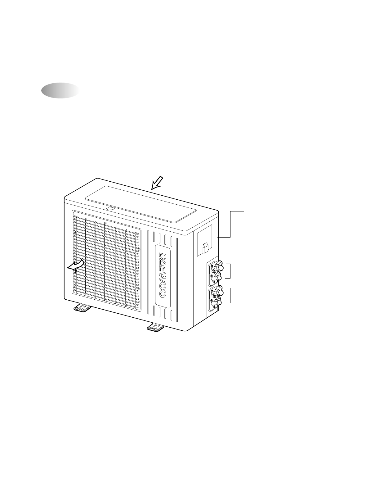
OUTDOOR UNIT
DMB-1822LH/1832LH/2112LH/2122LH
Inlet
Outlet
Outlet
Foot Cushion
800
Cabinet Front
Service Cover
Service Valve
Cabinet Side
Panel Top
Guide Support
Foot
325

10
This Installation section explains how and where to connect this new air conditioner. Please read make sure all accessories are included as shown below and read manual thoroughly. This Installation section is provided to assist the person knowledgeable in air conditioner installation and should not be installed by anybody who is not thoroughly familiar
with this type of installation. Please contact a professional installer if necessary.
ACCESSORIES SUPPLIED WITH THE UNIT:
COPPER TUBING:
Copper tubing supplied is available at most dealers or A/C shops. Make sure the new copper tubing has the same
specifications and diameter as the original copper tubing and is as short as possible.
Note:
The remainders except for No. 2, 7, 11 are contained in the indoor boxes.
BASIC ACCESSORIES
1
2
8
6
7
9
3
10 11
4
No. Description Qty.
1 Wall Bracket 2
2 Outdoor Unit Cover 1
3 Remote Controller
4 Deodorizing Filter
5 Electrostatic Filter
2
2
2
6 Remote Holder 2
No. Description Qty.
7 Foot Cushion 4
8 Concrete Nails 10
9 Remote Holder Screws 6
10 Wall Bracket Screws 16
11
12 Signal connection cord 2
Battery 4
5
12
4. INSTALLATION SECTION

11
OPTIONAL A CCESSORIES
1 2
4
3
5 6
ACCESSORIES NOT SUPPLIED WITH THE UNIT:
No. Description Part No. Qty Material Size Remark
1 Drain Hose Extension 3103200400 2 ID19.6 X 2m PVC Pipe
2 Tape 2TQ1007502 2 PVC 75W X 0.1T X 25m
3 Copper Tubing Extension
3104402600 2
1/4" Copper Tube X L5M
Wrapped with
insulator tube
3104402910 2
3/8" Copper Tube X L5M
4 Insulator Plate 3103301010 2 F-US 225 X 120 X 5T
5 Putty 2221040001 2 80g
6 Connection Cord 3112716320 2 3P X 6m
7 Cable tie 3172400500 8 L200 x W4.08
8 Fixture tie mount 3112000300 8 L24.5 x W15.5 x H11.5 x ø6.6
9 Cap wall 3100900600 2 PP
97 8

12
INSTALLATION DIAGRAM
Below is an overview for the connection of the Indoor unit to the Outdoor unit. The pages following will give detailed
instructions for full installation. Remember to read the complete Installation section and follow all the safety instructions
fully when installing the Indoor and Outdoor units.
OVERVIEW
This appliance must be installed according to national power supply acquirement.
NOTES:
• After installation it must be
possble for the user to
disconnect the power supply
plug.
•
If he AC outlet is a 3-pronged
type or other, have an
electrician install a new
outlet.
• Contanct service man when
replace the power cord set.
Drain
Hose
Ground Wire
(Not Supplied)
3/8" side piping
Signal Wire
1/4" side piping
Drain Hose
Wall
Wall
Cap
Drain
Hose
Pipes
(Not Supplied)
Signal wire
Wrap with
Tape
Copper
12000 BTU/h
or
9000 BTU/h
(9000BTU/h)
Tubing
At least 30cm
(11.8in) from unit
Maximum Height 7M (21Ft)
Maximum Length 15M (49Ft)
Any tube length between 7 and 15 meters must
be precharged with freon using the following calulation: (Length – 5) x 30 grams
Adding additonal tubing will decrease efficiency
60
cm
23 6
inches
cm
10
cm
3.9 inches
60
23.6
inches
70
cm
27.6
inches
AC Outlet
and Plug
Plug into 220V~240V
AC Outlet
(Not supplied)
10cm (3 95in)
from ceiling
30cm (11.8in) from
side wall
30cm (11 8in) from
side wall
10cm (3.95in) from
side wall
10cm (3.95in) from
side wall
Wall
Bracket
Connecting
cable
Connecting cable
(Not supplied)

13
INSTALLATION
1. Determine the type of wall (sheetrock, concrete, etc.)
and make sure it is strong enough to hold indoor unit.
Select an approximate position for the unit, taking the
required distances away from walls/AC outlet into
consideration.
INDOOR UNIT
• Do not install the unit in an area with direct sunlight, near
heat sources (radiator, etc.), or an area where leakage of
flammable gas may be expected.
• Select a position in the room, high on the wall, where the
whole room can be uniformly cooled.
• Select a location that can hold the weight of the unit and
where the copper tubing, drain hose and Indoor to Outdoor
Wire have the shortest distance to the Outdoor unit.
• Make sure the Indoor unit is installed at least 10cm (3.95in)
away from the top and left side wall and at least 30cm
(11.8in) from AC outlet and right side wall (see Overview
figure on previous page).
OUTDOOR UNIT
• Do not install the unit in an area near heat sources,
exhaust fans, or an area where leakage of flammable gas
may be expected.
• Do not install the unit in a humid, damp or uneven location.
• Select a location that is well ventilated .
• Leave enough room around the unit for air intake, exhaust
and possible maintenance.
2. Determine if the hole is to be made at the left or right
hole location.
10 mm
10 mm
150 mm 60 mm
3. Using drill with hole-cutting attachment or equivalent, cut
a hole 65mm (2.56") in diameter. The hole should be
made at a slight downward slant to the outdoor side.
Measure the thickness from the inside to outside edges
and cut a PVC pipe at a slight angle 1/4" shorter than the
thickness of the wall and insert pipe in wall.
4. For sheetrock, wooden or similar wall, measure down
from the ceiling using a level or tape measure and attach
the wall bracket to the wall using 4 screws. If you are not
able to line up the holes with the beams, use toggle
bolts. Make sure the wall bracket is even and flush
against the wall.
Indoor Outdoor
Cut at slight angle
CAUTION
• Before making hole, make sure there are no studs, pipes,
electrical wiring or conduit directly behind the area to be cut.
For Concrete, or similar type wall, make holes into the wall and insert concrete nails instead of screws.
INST ALLING THE WALL BRACKET :
To install the wall bracket, follow the procedures below. One hole is required for the tubing and may be either on the left or right side.
SELECTING A SITE:
10 mm
10 mm
150 mm 60 mm
9000 Btu/h Class
12000 Btu/h Class

14
INSTALLING THE AC CONNECTION WIRE T O THE INDOOR UNIT FOR A C POWER SUPPLY
The AC Connection wire is used to supply AC from the outdoor unit to the indoor units. To install AC connection wire,
follow the procedures below.
NOTE:
• This appliance must be installed according to National power supply requirement.
• If the supply cord is damaged, it must be replaced by the manufacuturer or its service agent or a similarly
qualified person in order to avoid a hazard.
• Make sure the outdoor unit’s AC cord is not connected to AC connection wire.
• When connecting wires, make sure they are fully inserted and minimum copper wire is exposed. If they are
not, shorting, overheating, no operation, etc. may occur.
• Be sure to comply with local codes on running a wire from the indoor to the outdoor unit.
1. Open the connection cover on the indoor unit to access
the connection area.
Remove the Connection Cover.
• Loosen the screw fixed at the Connection Cover.
• Remove the Connection Cover.
2. Fish the AC connection wire from the rear of the
indoor unit through the front of the unit.
For easier connection, make sure enough wire
is pulled through the front. Use the wire as
shown below:
3. To connect wires, loosen the screw in the
Terminal Block and insert the correct wires like
following figure.
Connect the Brown wire to the “L” connection,
Yellow/Green wire to the “” connection and
the Blue wire to “N” connection.
Screw
Screw (Special screw)
Blue
Yellow/Green
Brown
L
N
Brown Blue
Yellow/Green

15
4. Connect the wires to the housing and terminals on the control board individually according to the outdoor uint
connection.
indoor terminal
Connection
Cable
Connection
Cable
not insert
plug
Unit A
LN
indoor terminal
Unit B
LN
L1 N1
Outdoor terminal
Outdoor
L2 N2
Unit A Unit B
Brn
Y/G Brn Blu Brn Blu Y/G Brn Blu Y/G
Y/G Blu Brn Y/G Blu
LN
Power
Terminals
Signal
<INDOOR UNIT (Control Box)><INDOOR UNIT (Control Box)>
(9000 Btu/h) (12000 Btu/h)
Terminals
Signal
NOTE: We want you to observe bellow recommended specifications.
Part Name
Power plug
Power cable
Circuit breaker
Connection cable
Recommended specifications
250V 10/16A
Flexible, H05RN-F above 2.0mm
2
15A
H05RN-F 0.5 or 0.75mm2 x 3P x 6m

16
Left
Tubing
2. Make sure the drain hose and copper tubing are
wrapped with the rubber insulation. Using the tape,
wrap the AC connection wire, copper tubing and drain
hose together.
MOUNTING (INDOOR UNIT)
The Indoor unit must be mounted before connecting the AC connection wire, drain hose and copper tubing. To mount,
follow the procedures below:
1. The tubing can be extended in 4 directions as shown
below. No cutting is necessary for left/rear and
right/rear tubing connections. If using left or right tubing connections, remove the plastic area with a hacksaw so pipes can go through.
CAUTION:
•
Make sure the outdoor unit’s AC cord is not
connected to AC power when performing these procedures.
• Be sure to comply with local codes on running a wire
from the indoor to the outdoor unit.
• DO NOT LET THE AC CONNECTION WIRE
COME IN DIRECT CONTACT WITH THE TUBING
OR HOSE!
3. Shape the tubing so it can easily go through the hole
in the wall. Push the AC connection wire, copper tubing and drain hose through the hole in the wall angling
downward. Situate the indoor unit on the wall bracket
by lifting the indoor unit slightly above the wall bracket
and then down so it is securely locked in place.
Wall Bracket
Insert Putty
Drain Hose
CAUTION:
• When using the tube reamer, hold the tube downward and make sure no copper scraps fall into the tubing.
2. Make a flare at the end of the copper tube with a flare
tool.
Make sure the inside surface and edges are smooth
and the sides are uniform length.
1. Cut the copper tube extension to the desired length
with a tube cutter. It is highly recommended that 1 foot
is added to the requested length. After cutting, deburring may be necessary (see below diagram). Perform
this with a tube reamer.
BEFORE AFTER
PREPARING THE COPPER TUBING (NOT INCLUDED)
A copper tubing extension (not included) may need to be cut. If this is the case, it will also have to be deburred and
flared as shown below:
Flare tool
Flare nut
Connection
pipe
Right
Tubing
Right/Rear
Tubing
Left/Rear
Tubing

17
1. Remove the flare nut stoppers from the inside unit.
Determine the location of the copper tubing and
where the bends will be. Gently bend the copper tubing, making sure to use big angles so no crimping will
occur. Try to do this on the first try as repeated bending may break or crimp the tubing.
2. Remove the plastic stoppers from the tubing. Connect
the large and small copper tubing to the respective
extension and rotate the flare nut with your finger until
a smooth match is made. Make sure the copper
extension has foam rubber (insulation) on it.
Flare Nutcoupler
CONNECTING COPPER TUBES
To connect the copper tubes, follow the procedures below:
NOTE:
When removing the flare nut stopper from the inside unit, confirm “Ping”, sounds because the mixed gas is charged in
the inside unit,
3. Once a smooth match is made, tighten the flare nut
using a wrench. Be very careful not to strip the
threads or flare nut. Repeat this process for the small
and large tubing. When tightening the flare nut, use
another wrench to securely hold the coupler from
twisting and possibly damaging the tubing.
4. Remove the flare nut stoppers from the outdoor unit’s
valves. Connect the larger copper tubing to the larger
valve on the outdoor unit. Connect the smaller copper
tubing to the smaller valve on the outdoor unit.
5. Perform a leak test on all copper tube connections. To
prevent heat loss and damage to walls from condensation, the copper tube connections coming from the
wall must be insulated. Do this by wrapping foam rubber or equivalent around the connection approximately 8mm thick so no copper tubing is exposed.
NOTES:
• As with all wiring and hookups on this unit, make sure
the AC plug on the the outdoor units are unplugged.
• Be very careful not to strip the threads or flare nut.
• When insulating the connections, use foam rubber or
equivalent.
1. Connect the drain hose extension to the drain hose
coming from the indoor unit by loosing the clamp on
the extension using a phillips screwdriver, attaching
the hoses together and then tightening the clamp.
2. Run the drain hose, slanted downward, outside. If the
drain pipe is exposed
indoors, make sure it is
thoroughly insulated so
condensation does not
ruin walls or furniture or
come in contact with the
AC connection or extension. Also, do not crease
or form a trap in the tubing.
Wall Bracket
Insert Putty
Drain Hose
CONNECTING THE DRAIN HOSE
To connect the drain hose, follow the procedures below:

18
1. Remove the screw holding on the connection cover.
Remove the connection cover on the outdoor unit to
access the connection area.
3. Connect the wires to the housing and terminals on the control board individually as the following.
INSTALLING THE AC CONNECTION WIRE TO THE OUTDOOR UNIT FOR AC POWER SUPPLY
The AC connection wire is used to supply AC from the Indoor unit to the Outdoor unit. To install the AC connection wire,
follow the procedures below.
2. Route the AC connection wire into the opening on the
outdoor unit and through the wire holder. To connect
to the wire holder, loosen the screw on the wire holder, insert the wires through, then tighten the screw.
NOTES:
• Make sure the outdoor unit’s AC cord is not connected to AC power when connecting the indoor/outdoor wire.
• When connecting wires, make sure they are fully inserted and minimum copper wire is exposed. If they are not,
shorting, overheating, no operation, etc. may occur.
• Be sure to comply with local codes on running a wire from the indoor to the outdoor unit.
Yellow/Green
Blue
Brown
indoor terminal
Connection
Cable
Connection
Cable
not insert
plug
Unit A
LN
indoor terminal
Unit B
LN
L1 N1
Outdoor terminal
Outdoor
L2 N2
Unit A Unit B
Brn
Y/G Brn Blu Brn Blu Y/G Brn Blu Y/G
Y/G Blu Brn Y/G Blu
LN
Power
Connection
Cover

19
4. To connect wires, loosen the
screw in the Terminal Block and
insert the correct wires like
following figure.
Connect the Brown wire to the
“L” connection, the
Yellow/Green wire to the “”
connection, the Blue wire to the
“N” connection.
DMB-1822/1832/2112/2122LH

20
CONNECTING SIGNAL WIRES BETWEEN INDOOR UNITS AND OUTDOOR UNIT
The signal wires are used to inter-communicate indoor and outdoor’s signal, and attached to the indoor unit at first.
To install the signal wires to outdoor unit, follow the procedures below.
NOTE:
• Make sure the indoor & outdoor unit’s AC cord is not connected to AC power when connecting the signal
wires.
• When connecting wires, make sure they are fully inserted and minimum copper wire is exposed. If they are
not, shorting, overheating, no operation, etc. may occur.
• Be sure to comply with local codes on running a wire from the indoor to the outdoor unit.
• Must be careful to insert signal wire connectors where like color is like color.
1. Remove the screw holding on the connection
cover.
Remove the connection cover on the outdoor
unit to access the connection area.
3. Insert the indoor connector into the outdoor
connector from the PCB Board individually as
the following.
2. Route the indoor signal wire into the opening on
the outdoor unit and through the wire connector,
and insert the indoor connector into the outdoor
connector.
Connection
Cover
Indoor Unit A
White
Unit A
(White)
Unit B
(Red)
Outdoor PCB ASS'Y
White
Red
Red
Indoor Unit B
indoor unit A White – White
indoor unit B Red – Red

21
1. Tape the two copper tubes, drain hose (and the
electrical wiring if local codes permit) together with
the supplied tape. Make sure the electrical wiring
does not come in direct contact with the copper tubing or drain hose. Approximately 1 foot outside the
hole, let the drain hose out and separate from the
copper tubing and wiring.
Wall braket
Introduceti chit
Drain hose
2. Begin wrapping from the point the tubing comes out of
the outdoor unit and continue to the hole in the wall.
Leave no gaps or breaks and cover the entire length
of the tubing. As you wrap, overlap the previous turn
by half the width of the tape.
TAPING UP THE WIRE/TUBES/HOSE
After running the wire, hose and tubing outside, tape them up as shown below to insulate.
1. Apply the putty to any area on the outside hole that air
or rain can get into.
Apply Putty
Here
Tubing
2. After applying putty, insert the wall Cap at Indoor side
and Outdoor side.
Wall Bracket
Insert Putty
Wall Cap
Drain Hose
APPLYING PUTTY AND INSERTING WALL CAP
After running the wires and tubing outside, putty should be inserted around the opening on the outside to protect against
rain, wind, etc. To apply putty, see below:
Indoor side Wall
Outdoor side
3. Wrap the piping joints with the insulator plate and fasten it with vinyl tape.
pipe
Insulator Plate
vinyl tape
4. After wrapping the connection pipe with tape, fasten it
to the outside wall with saddles, etc.
Saddle
(Not supplied)
Wall cap
Pipe
Tape
3/8" side piping
Connecting cable
Signal Wire
1/4" side piping
Drain Hose

22
AIR PURGING
Air and moisture remaining in the refrigerant system may create
adverse conditions as indicated below:
• pressure in the system rises.
• operating current rises.
• cooling efficiency drops.
• moisture in the refrigerant circuit may freeze and block capil
-
lary tubing.
• water may lead to corrosion of parts in the refrigerant system.
Therefore, the indoor unit and tubing between the indoor and
outdoor unit must be evacuated to remove moisture from the system.
AIR PURGING WITH VA CUUM PUMP (TEST R UN)
Confirm each tube (narrow and wide tubes) between the indoor
and outdoor units has been properly connected and all wiring
for the test run has been completed. Remove the valve caps
from the wide and narrow service valves on the outdoor unit.
Note that both narrow and wide tube service valves on the outdoor unit are kept closed at this stage (shipping position).
Leak Test
1. With the service valves on the outdoor unit remaining closed,
remove the threaded cover on the wide tube service port.
(Save for reuse.)
2. Attach a manifold valve (with pressure gauge) and dry nitrogen gas cylinder to this service port with charge hoses.
CAUTION:
Be sure to use a manifold valve for air purging. If it is not avail
-
able, use a stop valve for this purpose. The “Hi” knob of the
manifold valve must always be kept closed.
3. Pressurize the system to no more than 150 P.S.I.G. with dry
nitrogen gas and close the cylinder valve when the gauge
reading reaches 150 P.S.I.G. Next, test for leaks with liquid
soap.
Lo Hi
Pressure
Gauge
Manifold Valve
Outdoor Unit
Indoor Unit
Charge Hose
Nitrogen Gas
Cylinder
(Vertical
Position)

Evacuation
1. Attach the charge hose end described in the leak test
area to a vacuum pump to evacuate the air remaining
at the tubing and indoor unit.
Confirm the ÒLoÓ knob of the manifold valve is open.
Then, run the vacuum pump. The operation time for
evacuation varies with the tubing length and capacity of
the pump. The following table shows the amount of
time for evacuation:
2. When the desired vacuum is reached, close the ÒLoÓ knob
of the manifold valve and stop the vacuum pump.
Finishing the job
1. With a hex wrench, turn the narrow tube service valve
stem counter-clockwise to fully open the valve.
2. Turn the wide tube service valve stem counter-clockwise
to fully open the valve.
To avoid gas from leaking when removing the charge hose,
make sure the wide tube service valve is fully open and
Model
DMB-1822LH
DMB-1832LH
DMB-2112LH
DMB-2122LH
STANDARD
LENGTH(m)
INDOOR
UNIT
Change am't(g)
per 1m
5
A15
15
15
15
15
15
6
15
B
A
B
A
B
A
B
5
5
5
turned all the way out.
3. Loosen the charge hose connected to the wide tube ser
-
vice port slightly to release the pressure, then remove the
hose.
4. Replace the threaded cover on the wide tube service port
and fasten it securely. This process is very important to
prevent gas from leaking from the system.
5. Replace the valve caps at both wide and narrow service
valves and fasten them securely.
This completes air purging with a vacuum pump. The air
conditioner is now ready to test run..
If tubing length is less than
33 ft. (10 m)
10 min. or more
If tubing length is longer than
33 ft. (10 m)
15 min. or more
Required time for evacuation when 30 gal/h vacuum
pump is used
CAUTION:
CAUTION:
Freon Extra Charge
To avoid nitrogen entering the refrigerant system in a liquid
state, the top of the nitrogen gas cylinder must be higher than its bottom when you pressurize the system. Usually, the
cylinder is used in a vertical standing position.
4. Do a leak test of all joints of the tubing (both indoor and outdoor) and both wide and narrow service valves. Bubbles
indicate a leak. Be sure to wipe off the soap with a clean cloth.
5. After the system is found to be free of leaks, relieve the nitrogen pressure by loosening the charge hose connector at
the nitrogen cylinder. When the system pressure is reduced to normal, disconnect the hose from the cylinder.
Lo Hi
Pressure
Gauge
Manifold Valve
Outdoor Unit
Indoor Unit
Charge Hose
Vacuum
Pump
23

24
TEST RUN
Check that all tubing and wiring have been completed correctly. Check again that the wide and narrow tube service
valves are fully opened. Turn on the power and run the system.
Service Valve Construction
• Valve Position Closed
The valve systems of both the wide and narrow tubes are turned all the way in. The unit is shipped from the factory in
this position and it is also used for Pump Down and Air Purging.
• Valve Position Fully Open
The valve stems of both the wide and narrow tubes are turned all the way out. This is normal operating and Test Run
position.
• Valve Position Half Open
With the narrow tube valve stem is turned to the halfway-down position. This position is used for pressure measurement and gas charging.
CAUTION:
When opening or closing the service valve stem, be sure to use a hex wrench.
PUMP DOWN
Pump Down means collecting all refrigerant in the outdoor unit without loss in refrigerant gas.
This is performed when the unit is to be relocated or the refrigerant circuit is serviced.
CAUTION:
Be sure to perform Pump Down procedure with the unit cooling mode.
Pump Down Procedure (execute the pump down of the unit A and unit B respectively)
1. Connect a low-pressure gauge manifold hose to the charge port on the wide tube service valve.
2. Open the wide tube service valve halfway and purge the air from the manifold hose using the refrigerant gas.
3. Close the narrow tube service valve (all the way in).
4. Turn on the unit’s operating switch and start the cooling operation.
5. When the low-pressure gauge reading becomes 1 to 0.5 kg/cm2 (14.2 to 7.1 psi), fully close the wide tube valve stem
and then quickly turn off the unit. At that time, Pump Down has been completed and all refrigerant gas will have been
collected in the outdoor unit.

3-W ay V alve
3-way valve(Liquid Side) 3-way valve(Gas Side)
Works Shaft position Shaft position Service port
Shipping Closed Closed Closed
(with valve cap) (with valve cap) (with cap)
1 Air purging Open Closed Open
(Installation) (counter-clockwise) (clockwise) (push-pin or with
vacuum pump)
Operation Open Open Closed
(with valve cap) (with valve cap) (with cap)
2 Pumping down Closed Open Open (connected
(Transfering) (clockwise) (counter-clockwise) manifold gauge)
3 Evacuation Open Open Open
(Servicing) (with charging cylinder)
4 Gas charging Open Open Open
(Servicing) (with charging cylinder)
5 Pressure check Open Open Open
(Servicing) (with charging cylinder)
6 Gas releasing Open Open Open
(Servicing) (with charging cylinder)
25

26
1
NAME AND FUNCTION OF PARTS
Indoor Unit
5. OPERA
TION
9000 BTU/h Class (DMB-1822LH unit A & B, DMB-2112LH unit B)
Electrostatic Filter
removes dust and
particles from the air
Deodorizing Filter
removes bad smells
from the air
Air Inlet
Remote
Controller
Receiver
Signal wire
Remote Controller
Fan Direction
(Up, Down)
Air Outlet
Antibacterial Filter
removes dust and
prohibits germs.
Lamp
9000 BTU/h Class (DMB-1832LH unit A & B, DMB-2122LH unit B)
Electrostatic Filter
removes dust and
particles from the air
Deodorizing Filter
removes bad smells
from the air
Air Inlet
Remote
Controller
Receiver
Signal wire
Remote Controller
Fan Direction
(Up, Down)
Air Outlet
Antibacterial Filter
removes dust and
prohibits germs.
Lamp

27
1 2 0 0 0 B TU / h Cla s s (DM B -2 1 1 2 LH u n it A )
Lamp
Electrostatic Filter
removes dust and
particles from the air
Deodorizing Filter
removes bad smells
from the air
Air Inlet
Remote
Controller
Receiver
Signal wire
Remote Controller
Fan Direction
(Up, Down)
Air Outlet
Antibacterial Filter
removes dust and prohibits
germs.
1 2 0 0 0 B TU / h Cla s s (DM B -2 1 2 2 LH u n it A )
Electrostatic Filter
removes dust and
particles from the air
Deodorizing Filter
removes bad smells
from the air
Air Inlet
Remote
Controller
Receiver
Signal wire
Remote Controller
Fan Direction
(Up, Down)
Air Outlet
Antibacterial Filter
removes dust and
prohibits germs.
Lamp

28
INDOOR UNIT (DMB-2112LH unit A (12000BTU/h))
■
Remote Control Signal Receiver
This place is the part to receive the signal if it receives
the signal, you can hear the signal “beep”.
■
When the remote controller is lost or outof-order, push the emergency button
(EMERGENCY) to operate by hand.
Open the front panel on emergency operating.
Remocon switch is usually used with remote
controller.
Indoor Unit Display Switch Panel
Timer (Yellow)
Lights-on during the time
of reservation mode.
Quick (Red)
Lights-on during the time
of Quick Mode.
ON (Red)
Lights-on
during the operation
Air clean (Green)
Lights-on
during the operation
ON AIR
CLEAN
QUICK TIMER
EMERGENCY REMOTE

29
■
Remote Control Signal Receiver
This place is the part to receive the signal if it receives
the signal, you can hear the signal “beep”.
■
When the remote controller is lost or outof-order, push the emergency button
(EMR.) to operate by hand.
Open the front panel on emergency operating.
Remocon switch is usually used with remote
controller.
Indoor Unit Display Switch Panel
Timer (Yellow)
Lights-on during the time
of reservation mode.
Quick (Red)
Lights-on during the time
of Quick Mode.
ON (Red)
Lights-on
during the operation
Air clean (Green)
Lights-on
during the operation
EMR. REMOCON
INDOOR UNIT (DMB-2122LH unit A (12000BTU/h))

30
■
Remote Control Signal Receiver
This place is the part to receive the signal if it receives
the signal, you can hear the signal “beep”.
■
When the remote controller is lost or outof-order, push the emergency button
(EMR.) to operate by hand.
Open the front panel on emergency operating.
Remocon switch is usually used with remote
controller.
Indoor Unit Display Switch Panel
Timer (Yellow)
Lights-on during the time
of reservation mode.
Quick (Red)
Lights-on during the time
of Quick Mode.
ON (Red)
Lights-on
during the operation
Air clean (Green)
Lights-on
during the operation
EMR. REMOCON
INDOOR UNIT (DMB-1822LH unit A or B, DMB-2112LH unit B (9000BTU/h))

31
■
Remote Control Signal Receiver
This place is the part to receive the signal if it receives
the signal, you can hear the signal “beep”.
■
When the remote controller is lost or outof-order, push the emergency button
(EMR.) to operate by hand.
Open the front panel on emergency operating.
Remocon switch is usually used with remote
controller.
Indoor Unit Display Switch Panel
Timer (Yellow)
Lights-on during the time
of reservation mode.
Quick (Red)
Lights-on during the time
of Quick Mode.
ON (Red)
Lights-on
during the operation
Air clean (Green)
Lights-on
during the operation
EMR. REMOCON
INDOOR UNIT (DMB-1832LH unit A or B, DMB-2122LH unit B (9000BTU/h))
32
A
AIR IN
B
AIR OUT
Connection Cover
Remove cover to access the
AC connection to the indoor unit.
Service Valves
The indoor and outdoor units
are connected by copper tubes
which are connected here.
oor Unit

33
e of Each Button
2
REMOTE CONTROLLER
MODE
SLEEP
ON/OFF
TIMER
ENTER/
CANCEL
FAN SPEED
TURBO/MILD
Display
Displays information
pertaining to unit.
TURBO/MILD
Press to be colder the unit.
TIMER ENTER/CANCEL Button
Press to enter a timer setting or
to cancel timer setting
MODE Button
Press to cycle through the modes
(Auto/Quick/Cooling/Fan/Dry)
SLEEP Button
Press to set the unit for
the sleep mode.
FAN DIR.
FAN DIR. Button
Press to select up/down
direction for fan.
ON/OFF Button
Press to turn the unit
on or off.
TEMPERATURE Buttons
Press to raise or lower
the desired temperature.
FAN SPEED Button
Press to select the fan speed
(High " ", Middle " ",
Low " ").
COVER
Slide down to access most
of the remote buttons.
Slide down further to
access the battery
compartment.
AUTO
REMOTE CONTROLLER
Press to set the unit off or on time.
(0.5, 1, 1.5, 2, 2.5, 3, 4, 5, 6, 8, 8,
10, 12, 16, 20, 24hr)
Timer O/OFF Button

34
R ep la cing B a tteries
3
R EM O TE CO N TR O LLER DIS P LA Y
Open the cover after
pressing the arrow
direction and pulling out.
Put the dry cell by +, -
direction.
Close the cover after
pushing into arrow
direction.
1
2
3
R
E
M
E
N
R
E
R
+Ð
+Ð
R
E
M
E
N
R
R
MODE Indicators (Auto/Quick/Cool/Fan/Dehumidifier/Heat)
Lights to indicate the mode selected.
TIMER Indicators (Include sleep)
Lights to indicate the timer function mode.
TEMPERATURE & RESERVATION TIME lndicator
Lights to indicate the temperature or time.
FAN DIRECTION Indicators
Lights to indicate the
fan direction.
NATURAL Indicator
Lights to indicate the
speeds simulating a breeze.
FAN Indicators
Lights to indicate
the fan speed.
AUTO

35
If you set time in OFF-Timer Mode, the unit will stop at the set time.
If you set time in ON-Timer Mode, the unit will run at the set time.
(1) Range of setting temperature: 18~32°C
(2) Setting temperature: Operating temperature of compressor
If the Indoor Unit Display receive the signal of Remote Controller , y ou can hear the signal "beep –" or "beep,
beep".
(1) In the case of receiving ON/OFF signal-"beep" "beep"
(2) And so on-"beep"
imer
4
DESCRIPTION OF FUNCTIONS
Unit ON
Unit OFF
SET Time
HOUR
ON
OFF
mer
Unit ON
Unit OFF
SET Time
HOUR
ON
OFF
ol of Room T emperature
r
COMP (ON)
*RT: ROOM TEMPERATURE
DT: DESIRED TEMPERATURE
COMP (OFF)
-1°C
(COOLING)
(RT-DT)
COMP (OFF)
COMP (ON)
HEATING
(RT-DT)
+1°C +4°C+1°C

36
Fa n S pe ed (Ind oo r Un it)
(1) Motor speed (High speed, middle speed, low speed).
(2) Remote controller setting fan speed. (Auto, L, M, H, Natural)
(3) Relation of operating mode between fan speed.
(4) Automatic Operation
If the unit is set in 'AUTO' mode, the unit operates automatically according to the room temperature to keep the
room temperature comfortable.
0 C
L
M
H
1 C2C
(R.T-D.T)
(D.T)
0 C
L
M
H
1 C2C
(DT-RT)
(COOLING)
(HEATING)
FAN ONLY COOL
DEHUMI-
AUTO QUICK HEAT
DIFICATION
H HHLHH H
M MML MH M
L LLLLH L
Auto X Auto L Auto H Auto
Natural Natural Natural L Natural H Natural

37
(1) When you are going to sleep, select sleep switch and the unit controls the room to the desired temperature.
(The unit will not operate after 4 hour)
(2) For changing the temperature.
(3) To cancel sleep mode, press the SLEEP button again or press the MODE button once.: the SLEEP
indicator will disappear in the display.
Mode
0 0.5 1.0 HOUR
(COOLING CYCLE)
DT
+0.5°C
+0.5°C
+0.5°C
0 0.5 1.0 HOUR
(HEATING CYCLE)
DT
–0.5°C
–0.5°C
–0.5°C
Prevention of Indoor Unit
When the unit operates at low ambient temperature, frost may appear on the Ev aporator. When the indoor coil
temperature is lower than 0°C at the end of 10 minutes of continuous compressor operation from the start, the
microcomputer of the unit stops the compressor to protect the unit from the frost. The control procedure for
indoor coil freeze protection.
1) The compressor and outdoor fan turn off.
2) Indoor fan operates according to user set speed.
3) The normal operation returns when the indoor coil
temperature is higher than 7°C or equal to 7°C.
4) In case of operating only the 9K indoor unit in the
cooling mode, the outdoor fan is
controlled according to the temperature of the
condenser sensor as shown below .
-1°C+7°C
Compressor and
Outdoor Fan
ON ON
OFF
Indoor Fan
Set speed
OUTDOOR
FAN MOTOR
CONDENSER
SENSOR TEMP.
OFF
ON
46°C53°C
(Indoor coil temperature)
(Condenser sensor temp.)

38
(2) Selecting Operating Mode Again
Room temperature meets desired temperature and the compressor stops running over 30 minutes, then the unit
selects operating Mode again.
3 min. Time Delay of Compressor
In normal operation, there is a time delay of three minutes between turn off and turning back on including initial
power up.
(RT: Room temperature)
(1) When the remote controller is lost, damaged or the battery is discharged, the Emergency operation can be
used to run the unit.
(2) The setting conditions of Emergency operation are as follows.
Operation mode: Quick
Preset temperature:18 : Cooling, 32 : Heating)
Fan speed: High
You cannot operate with remote controller.
Emer gency Operation
ROOM TEMPERATURE
DT
-2
R
T
DT
-2
RT
DT+3
DT+3
OPERATING MODE
Heating
Dehumidifier
Cooling
FLAP POSITION
Heating P
osition
Cooling P
osition
Cooling P
osition
>
*
*
*
!
R
T
>

39
1) Cooling Mode
When the room temperature is higher than 22
Fan Speed: Super high speed
Air discharge direction: Fixed
Set temperature: 18 (Fixed)
Compressor and Outdoor Fan
The air discharge direction procedure is below
Fixed Up/Down
Up/Down Fixed
The option is LEFT/RIGHT direction.
1) Heating Mode
When the room temperature is higher than 22
Fan Speed: Super high speed
Air discharge direction: Fixed
Set temperature: 18
Compressor and Outdoor Fan
The air discharge direction procedure is below
Fixed Up/Down
Up/Down Fixed
The option is LEFT/RIGHT direction.
Dehumidification Mode
Air Discharge Direction(only remocon operation)
Quick Mode(Power ful Cooling & Heating)
The air discharge direction procedure is below.
Fixed Up/Down Fixed
Up/Down
Desired temperature < Room temperature
Outdoor Fan, Compressor : ON
Indoor Fan : Low speed
Desired temperature Room temperature
Compressor : 3 min/ON, 5 min/OFF
Fan Speed : low speed
Room temperature 18
Compressor : OFF
Fan speed : Low speed
COOLING POSITION
HEATING POSITION
(Fixed)
<
=
>
=

40
iagnostic Function
The control will contain diagnostic test to verify the integrity of the system.
LED BLINK PATTERN CASE NOTE
Room Sensor open or Short •Continuously working to fix room
temperature 18°C in heating mode.
• Continuously working to fix room
temperature 32°C in cooling mode
• I/D sensor open or short • It doesn’t work.
• O/D sensor open or short • It doesn’t work.
• Compressor or electrical parts • Showing them at only Emergency
of compressor error. mode but continuously working.
• Gas leak
• Communication error between • Check connection and restart.
I.D.U and O.D.U
• 4-Way Valve or electrical parts of • Showing them at only Energency
4-Way valve. mode but continuously working.
• Operation mode is different from
the other unit.
0.2S
1S
ON + Airclean LAMP
TIMER LAMP
ON + Airclean LAMP
Timer LAMP
ON + Airclean LAMP
Quick LAMP and
Timer LAMP
ON LAMP and
AIr Clean LAMP
CODE1
CODE2
CODE3
CODE4
CODE5
CODE6

41
6. WIRING DIAG RA M
DM B -1 8 2 2 / 1 8 3 2 LH

1
M A IN ELECTR IC PA R TS
DM B -1 8 2 2 / 1 8 3 2 LH
PART NAME PART CODE SPEC. QUANTITY REMARK
Fan Motor 3108008700 YDK-8-4B 2
Fan Motor Capacitor 3106900300 1.0uF 400VAC 2
Fuse 5FVLB3152L 250V 3.15A 2
Stepping Motor 3108003900 GSP-24SW-061 2
Terminal Block 3108914100 JXO-CH-3P 2
Compressor 3RC0020KM1 RBB095M011 2
Fan Motor 3118002400 A2919BA010 1
Dual Capacitor 3116903400 5+25uF 400VAC D50 1
Terminal Block
3118800200 JXO-CH-2P 1
3108912320 DTB-04P 1
Reversing Valve 3105401010 STF-0101 2
Solenoid Coil 3109700110 STF-01AH897A1 2
Outdoor
Unit
Indoor
Unit (9K)
42

43
DM B -2 1 1 2 / 2 1 2 2 LH

44
DM B -2 1 1 2 / 2 1 2 2 LH
PART NAME PART CODE SPEC. QUANTITY REMARK
Fan Motor 3108008700 YDK-8-4B 1
Fan Motor Capacitor 3106900300 1.0uF 400VAC 1
Fuse 5FVLB3152L 250V 3.15A 1
Stepping Motor 3108003900 GSP-24SW-061 1
Terminal Block 3108914100 JXO-CH-3P 1
Fan Motor 3108008800 YDK-8-4B/A 1
Fan Motor Capacitor 3106900300 1.0uF 400VAC 1
Fuse 5FVLB3152L 250V 3.15A 1
Stepping Motor 3108000100 MP28GA (L=400mm) 1
Terminal Block 3108914100 JXO-CH-3P 1
Compressor
3RC0020KM1 RBB095M011 1
3RC0030CM0 RCB120M001 1
Fan Motor 3118002400 A2919BA010 1
Dual Capacitor 3116903400 5+25uF 400VAC D50 1
Terminal Block
3118800200 JXO-CH-2P 1
3108912320 DTB-04P
Reversing Valve 3105401010 STF-0101 2
Solenoid Coil 3109700110 STF-01AH897A1, L600 2
Indoor
Unit (12K)
Outdoor
Unit
Indoor
Unit (9K)
45
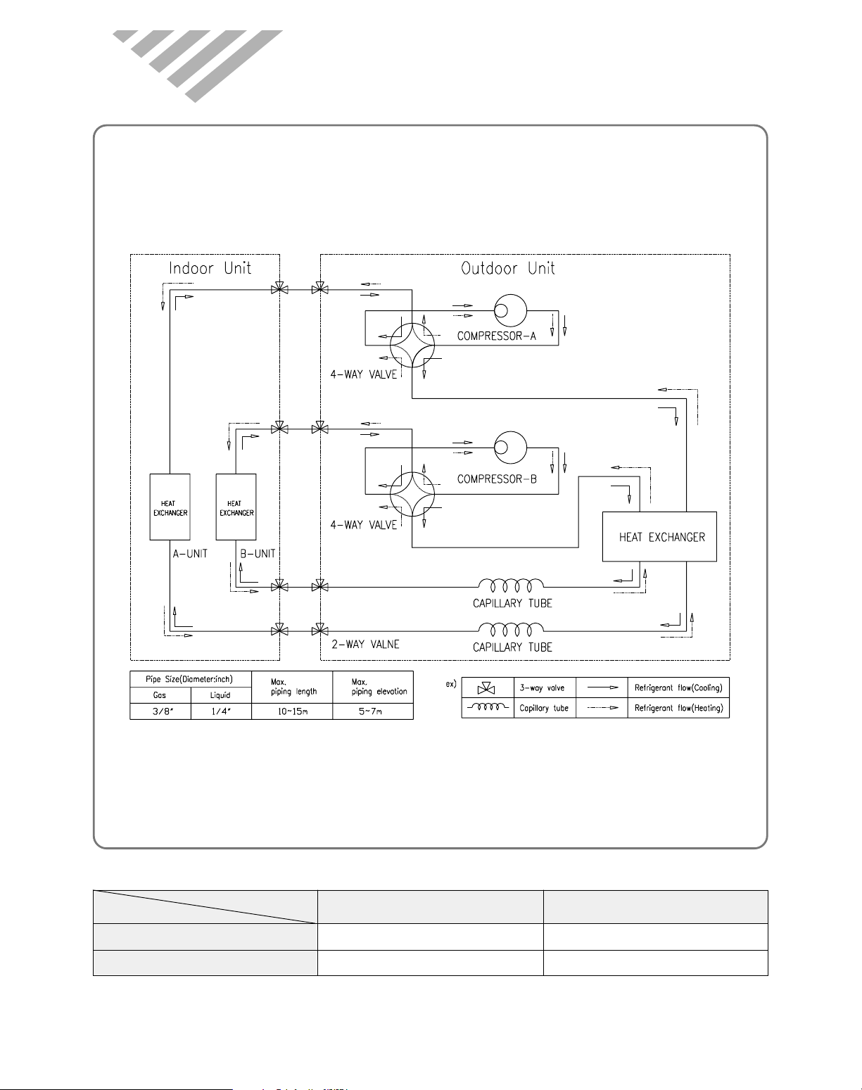
7. REFRIG ERA NT C YC LE
1) DMB-1822/1832LH unit A&B, DMB-2112/2122LH unit B.
2) DMB-2112/2122LH unit A.
Contents
Classes
Capillary Tube
Charge Quantity
9000 Btu/h Class
ID 1.6 x L1270
750 g
12000 Btu/h Class
ID 1.6 x L1000
1150 g
46
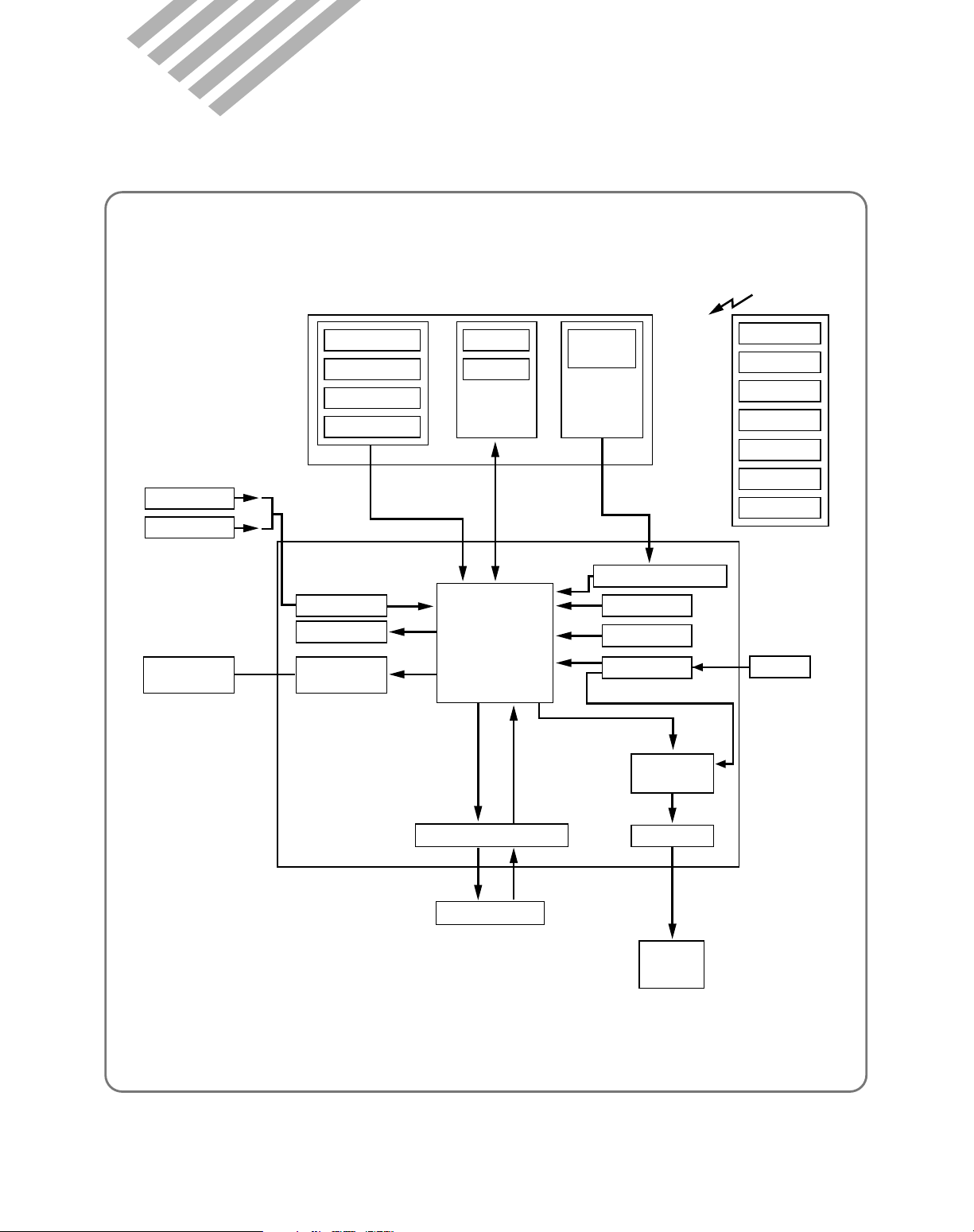
8. C O NTRO L BLO C K DIAG RA M
Indoor fan
motor
Communication
O.D.U
TRIAC
DC12V
Operating Mode
Fan Speed
Timer Selection
Flap Position
Unit on lamp
Room air temp.
Indoor coil temp.
Air clean lamp
Quick lamp
Remote
Emergency
Operation
Signal
receiver
Timer lamp
A/D converter lnitialization
Clock generation
DC power supply
Circuit for
TRIAC control
DC 12V
Circuit for signal receiver
MICRO
CONTROLLER
Beeper
circuit for
motor driving
Stepping
motor
Temp. Setting
ON/OFF
SLEEP
REMOCON
STEPPING MOTOR
ON/OFF
DC5V
IN D O O R PA R T
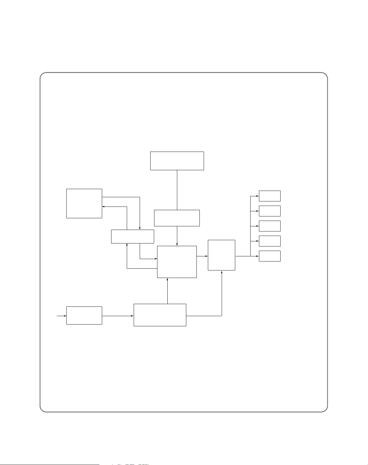
47
in DOOR
unit
OD sensor
TRANS
Former
Micro
Controller
A/D Converter
Communication
Relay
Out put
Driver
RL 1 Comp(B)
4W(A)
4W(B)
FAN
COMP(A)
RL 2
RL 3
RL 4
RL 5
DC POWER
12V, 5V
DC 12V
AC 220V
OUT DOOR P ART

48
9. TROUBLE SHOOTING
Outdoor unit does
not run?(note. 1)
Does
the compressor run
normally?
Indoor unit does
not run(note 1)
Check the failure
code according to
the self diagnostic
(note 2)
Is the unit
display
mormal?
check the failure
code according to
the self-diagonostic
(note 2)
Normal
check the
connecting
point of
magnetic
contactor
YES
YES
YES
YES
NO
NO
YES
Trouble
Is the power
applied to the
unit
Is the
power normal?
check the voltage between
Y & L of terminal
block
press the power ON/OFF
button on remote controller
Does the
beeper beep two
times?
Is the display
all off?
¥ Check the connector on display
PCB connected to control PCB
¥ Check the display PCB itself
Check power supply mains
or interconnection wires
Check the wiring of indoor
Is the
switch position
on switch pannel at
"Remote"
Does
control PCB
status LED repeat one
second "on and
off"?
¥ control PCB fault
¥ Micom or reset
IC fault
¥ Check the remote signal receiver
¥ Check the connection between signal
receiver and control PCB
Place the switch
position to the
"Remote" and then
Check it once
more
YES
NO
YES
NO
NO
NO
NO
YES
YES
YES
YES
YES
NO
NO
NO
Is the
unit display
normal?

49
Note 1)
1 Neither indoor unit nor outdoor unit runs.
Check the following points first. (There are f ollowing case in normal operation)
a. Is the timer mode set the "timer ON".
b. Is the timer mode set the "timer-OFF" and the time had passed?
2 Neither outdoor fan nor compressor runs while indoor fan runs.
Check following points first. (There are f ollowing cases in normal operation)
a. Is the temperature set point suitable?
b. Has the 3 minutes time guard for compressor operated?
iagnostic Function
Error CODE Display Check point
1 ON+Air clean LAMP I/D Sensor Registance check
1 time blink I/D Sensor Connection check
2 Timer LAMP O/D Sensor Registance check
1 time blink O/D Sensor Connection check
3 ON+Air clean LAMP Compressor and its electrical parts check
2 times blink Leakage check.
I/D Sensor assembly check
4 Timer LAMP Communication wire check
2 times blink (between I.D.U and O.D.U)
5 ON+Air clean LAMP 4-way and its electrical parts check
3 times blink Leakage check.
6 ON+Air clean LAMP check operation mode each two Indoor units.
and Quick+Timer LAMP blink

50
Confirm following statement.
When the unit operates normally , Sometimes the outdoor unit and indoor unit cannot operate.
1 Check the function is it timer mode?
2 The function is in the sleep mode and is the setting time over?
3 Is the setting mode DEHUMIDIFIER mode?
4 When the unit is DEHUMIDIFIER mode while in the auto mode, the outdoor unit and indoor unit
sometimes does not run.
The power is applied to the unit
Check the voltge between and
of terminal block
Y
L
Check the
Breaker or Fuse
Self Diagnostic
function is ON
Check according to
self Diagnostic function
Control P.C.B defect
Check the indoor unit display
is the display all off?
Press the ON/OFF switch of
Remote Control
Is the indoor unit display all off?
Pull out the power plug
and then insert the power plug
after 5 second
Control P.C.B is normal
Recheck from the beginning
Rating voltage more than 90%
Rating voltage
under 90%
No No
No
Yes
Yes
er Indoor Unit nor Outdoor Unit Runs

51
Check rotation of indoor fan
Rotate indoor fan by hand
Check input Voltage of Fan
Motor connector at power P.C.B
Check the winding resistance of
Indoor unit fan motor
Check the fan motor capacitor
Check the connecting wire of
indoor fan motor
Run again
Check the starting of indoor fan motor
Run again
Check the F an Motor
bearing and fan
Check the power P.C.B.
The circuit for triac control
Change of fan motor
Normal
NO
Rating voltage
under 85%
Open or short
No
YES
Rating V oltage more than 90%
Normal
oor Unit Runs but Indoor Fan Does Not Run

Confirm following statement.
When the unit operate normally , Sometimes the outdoor unit and indoor unit cannot operate.
1 Is the setting temperature proper?
2 Is the unit during 3min. Time delay of compressor.
3 During frost prevention of lndoor unit.
4 During dehumidifier mode.
oor Fan and Compressor Do Not Run
Check the voltge between and
of indoor unit terminal
N
L
Check the voltge between and
of outdoor unit terminal
N
L
Check compressor,
outdoor fan motor individually
Check the
connecting wire
Check the wiring
and voltage
within doors
Rating voltage
under 85%
Rating voltage
under 85%
52

53
- Check the following at cooling mode
Check the voltge between and
of indoor unit terminal
N
L
Check the voltge between and
of outdoor unit terminal
N
L
Check the wiring of outdoor unit
Check the compressor
(Check the winding resistance)
Check the compressor capacitor
Check the connecting
wire between indoor
and outdoor.
Change the control
P.C. B
Change the
compressor.
Check the control P.C.B
the circuit for relay
driving.
Rating voltage
less than 85%
NG
Open or Short
Rating voltage
less than 85%
Rating voltage more than 90%
Rating voltage more than 90%
OK
Compressor Does not Run

DM B -1 8 2 2 / 2 1 1 2 / 2 1 2 2 LH (O u tdo or)
10. PC B DRIV ING DESC RIPTIO N
1
P CB CIR CU IT DI A G R A M


DM B -1 8 2 2 / 2 1 1 2 / 2 1 2 2 LH (9 K in do or)


DM B -2 1 1 2 / 2 1 2 2 LH (1 2 K in do or)

57
PART NAME SPEC QTY LOC.
WAFER YW396-03AVD 1 CN1
WAFER YW396-03AVD(BLACK) 1 CN2
WAFER YW500-02V 1 CN6
PIN GP881205-2(187) 1 CN4
WAFER YFW800-01D 1 CN3
WAFER YFW800-01D(RED) 1 CN5
WAFER SMW250-05 1 CN10
WAFER SMW250-05(RED) 1 CN9
WAFER SMW250-02 1 CN8
WAFER SMW250-02(RED) 1 CN7
DIODE 1N4004 TAPE 6 D1,2,3,4,5,6
C-MULTI 104Z, CR0561B-Z5U 1 CC11
C-CERA 104Z,50VDC 5 CC1,2,3,8,9
C-CERA 103Z,50VDC 5 CC4,5,6,7,10
C-ELEC 2200uF 35V SD 1 CE1
C-ELEC 1000uF 25V SD 1 CE2
C-ELEC 100uF 16V SD 1 CE3
C-ELEC 10uF 16V SS 1 CE5
C-ELEC 1uF 50V SS 1 CE4
RESISTOR 1/4W-12.7KF 2 R3,14
RESISTOR 1/4W-10KJ 4 R7,8,15,16
RESISTOR 1/4W-5.6KJ 1 R1
RESISTOR 1/4W-1KJ 7 R2,5,6,9,10,11,12
RESISTOR 1/4W-330J 2 R4,13
RESISTOR 1/4W-202J 3 R17,(18),19
RESISTOR ARRAY 6A 103J 1 RA1
FUSE 250V 50T 3.15A 1 FUSE
FUSE CLIP AFC-520 2 FUSE CLIP
VARISTOR 15G561K 1 VAR
C-LINE ACROSS 275V 104K 1 CL1
HEAT SHINK 33(H)*23*17 1 HS1(IC2)
WASHER 3*6 1
SCREW T2S TRS 4*12 MFZN 1
JUMPER 10mm 5 J1,2,3,4,5
PCB OD CONTROL DMB-2COMP 1
RELAY US11-12S 3 RL2,3,4
RELAY UKH-12S 2 RL1,5
IC REGULATOR KIA7812P 1 IC2
IC REGULATOR KIA7805P 1 IC3
TR KRC102M 2 TR3,4
TR KRA1270Y 2 TR1,2
IC RESET KIA7042P 1 IC4
RESONATOR CST8.00MTW,8MHZ 1 OSC
IC MICOM TMP47P443VN 1 IC1
IC DRIVE KID65004AP 1 IC5
OUTDOOR CONTROL PCB ASS'Y
58
PART NAME SPEC 9K 12K LOC.
WAFER YW396-03AV(RED) 1 1 CN1
WAFER YW396-05AV 1 1 CN2
WAFER YW396-03AV 1 1 CN3
WAFER SMW250-05 1
WAFER SMW250-05(RED) 1
WAFER SMW250-02 1
WAFER SMW250-08 1 1 CN6
WAFER SMW250-06 1 1 CN9
WAFER 5267-04A 1 1 CN11
WAFER YFAW254-02 1 1 TEST
C-CERA 104Z,50VDC 4 4 CC1,2,8,9
C-CERA 103Z,50VDC 8 8 CC3,4,5,6,7,10,11,12
C-ELEC 470uF 25V SD 1 1 CE1
C-ELEC 100uF 16V SD 1 1 CE2
C-ELEC 10uF 16V SS 1 1 CE4
C-ELEC 1uF 50V SS 1 1 CE3
RESISTOR 1/4W-12.7KF 2 2 R9,10
RESISTOR 1/4W-10KJ 6 6 R4,19,20,33,34,37
RESISTOR 1/4W-5.6KJ 2 2 R3,36
RESISTOR 1/4W-1KJ
16 16
R5,6,12,13,14,15,16,17,
R21,22,23,24,25,26,32,35
RESISTOR 1/4W-330J 2 2 R7,8
RESISTOR 1/2W-1KJ 1 1 R2
RESISTOR 1/4W-15.0KF 1 R27
RESISTOR 1/4W-18.2KF 1 R27
RESISTOR 1/4W-24.9KF 1 R28
RESISTOR 1/4W-11.1KF 1 R28
RESISTOR 1/4W-12.4KF 1 R29
RESISTOR 1/4W-28.0KF 1 R29
RESISTOR 1/4W-3.24KF 1 R30
RESISTOR 1/4W-8.45KF 1 R30
RESISTOR 1/4W-28.0KF 2 R27.28
RESISTOR 1/4W-2.87KF 2 R29,30
RESISTOR 1/4W-24.3KF 1 R31
RESISTOR 1/4W-12.4KF 1 R31
RESISTOR ARRAY 6A 103J 1 1 RA1
C-ARRAY F5 104Z 1 1 CA1
FUSE 250V 50T 3.15A 1 1 FUSE
FUSE CLIP AFC-520 2 2 FUSE CLIP
VARISTOR 15G561K 1 1 VAR
C-LINE ACROSS 275V 104K 2 2 CL1,CL2
JUMPER 10mm 1 1 JS1
BUZZER DP-2520BA 1 1 BZ1
PCB ID CONTROL 130*76*1.6T(FR4) 1 1
COIL 130uH 3A 1 1 L1
IC REGULATOR KIA7805P 1 1 IC2
TR KRC102M 4 4 TR1,4,5,7
TR KRA1270Y 1 1 TR6
IC RESET KIA7042P 1 1 IC3
RESONATOR CST8.00MTW 1 1 OSC
TRIAC SM3JZ47 1 1 T1
PHOTO COUPLER TLP560J 1 1 PT1
IC MICOM TMP87PH46N 1 1 IC1
IC DRIVE KID65004AP 1 1 IC4
CN4
CN4
CN5
INDOOR CONTROL PCB ASS'Y
59
Power Supply(1)
DESCRIPTION
DC Power Supply in circuit needs +12V and +5V. +12V is used for Triac Driving Photo Triac, Buzzer Driving
Swing, Sweep Motor.
And it is regulated +5V DC by Regulator IC7805.
{
Zero cross
Communication line
12V
GND
CN4
O.D.U
I.D.U
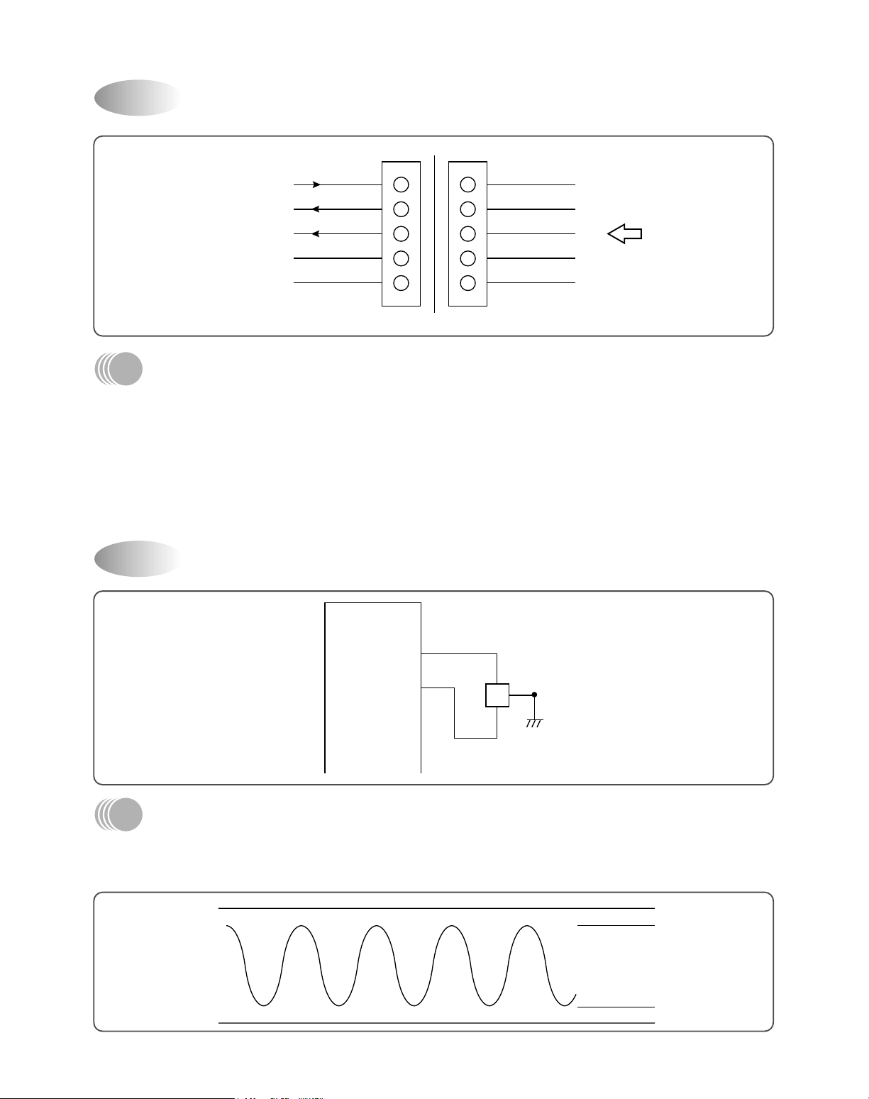
Oscillator(2)
19
OSC
8M
20
VDD-10%
V
SS
+10%
Fig 2-1
DESCRIPTION
Oscillatory Frequency drive Micom, it is made up 8MHz resonator oscillatory Freqency.
Ocillatory wave is as following Fig 2-1.

60
Room temperature and Evaporator temperature Sensor Input
DESCRIPTION
Number 24, 25 of Micom is Terminal of A/D convertor Input.
Room temperature and Evaporator temperature is sensing by change of Thermister Resistance, Micom is put
in 5V by ratio between R9 (12.7KΩ) and R10 (12.7KΩ).
Relation between temperature and voltage is following Table 3-1.
CC3, 4 is Noise filter.
Temperature
(°C)
No. 1 No. 3
-5 1.127 1.127
0 1.378 1.378
5 1.650 1.650
10 1.936 1.936
15 2.228 2.228
Voltage (V)
Table 3-1
Sensor(3)
I/D SENSOR
ROOM SENSOR
R7R6330
330
CC3
103
103
CC4
24
25
MICOM
CN9
R9
12.7KF
R10
12.7KF

61
T riac Driving(4)
DESCRIPTION
Number 13 Terminal of Micom is put out Pulse Output, by way of Buffer it is driving Photo Triac is supplied
Trigger Signal.
Trigger Test of Triac is detected Zero Cross Part of AC input and it is triggered from Zero Cross part to Time
delay part according to Fan Speed. (Ref. Fig 4-1) SN1 is Snubber.
N
L
AC 220V
TO MOTOR
T1
SM3JZ47
L1
12
130µH
3A
SN1
0.1µF
120Ohm
TLP561
PT1
12V
R2
TRI C102M
1K
1/2W
MICOM
13
AC220V
TRIGGER
MOTOR
INPUT
Fig 4-1
LOW SPEED
MEDIUM SPEED
HIGH SPEED

62
DES CR IPTI O N
Signal from Remote Controller put in only Control Data Signal at Micom Terminal of Number 33, which is gotten
fid of Carrier (38KHz) from Receive Module. Signal Wave repeat third as following Fig 5-1.
But in Secondary Wave Custom Code is Reversed Face.
LEADER CODE
CUSTOM
CODE
DATA
CODE
CHECK
SUM
TAILER
9ms 4.5ms 16bit 16bit24bit 8bit
Fig 5-1
Fig 5-2
BIT STRUCTURE
R em ote Contro ller (5 )
0.56ms 0.56ms1.69ms
1.12ms 2.25ms
bit 0 bit 1
S ele ctin g M od e(6 )
(SELECT S/W INPUT, OUTPUT)
MICOM
14
R5
1K
10K
R4
5V
CC7
103
P2
MODE
SELECT
PUSH S/W
DES CR IPTI O N
There are Mode according to SW position as
following Table 6-1.
According as port of fixed Micom is Low, the unit is
operating as following Table 6-1.
Table 6-1
POSITION MODE
OPEN REMOCON
GND EMERGENCY

63
DESCRIPTION
MICOM Pow er is supplied 5V at Number 42 using VDD, Number 19, 20 Using Oscillator.
Micom Power Supply(7)
VDD 42
CE4
10µF
16V
CC9
104
+
5V
22
21
19
OSC
8MHz
20
VSS
MICOM

64
DESCRIPTION
V oltage less than about 0.8V put in Micom Terminal of Number 18 and then Micom reset. Reset IC detect
Pow er ON and Voltage less than 4.25V, and then send Reset Signal.
Reset(8)
R3 5.6K
1K R13
18
CC6
CE3
4.7uF/50V
IC3
7042P
10.3
MICOM
4.25V
H
L
t
t
POWER
ON
Vcc (+5V)
DELAY TIME
FOR POWER ON
RESET

65
DESCRIPTION
Micom 35 Terminal put out Buzzer Driving Pulse,
its output is driving Buzzer through Buffer.
Ocillatory Frequency of buzzer is selected by
internal Micom.
This unit is setting at 4KHz.
VCC
12V
MICOM
35
R6
1K
BZ1
Buzzer Driving(10)
DESCRIPTION
Indoor Fan Motor RPM is set by each registance .
(R27, R28, R29, R30, R31)
30
29
28
27
26
1K
1K
1K
1K
1K
R26
R25
R24
R23
R28
R29
R30
R31
R22
MICOM
CA1
F5 104Z
RA1 R27
heat/low
heat/high
cool/low
cool/high
monitoring
6A 103J
I/D F AN RPM SETTING

66
DESCRIPTION
It defect Zero Cross part of Trans output voltage, Transistor TR1 is used to put in the Micom.
Detail Driving is as following Fig 11-1.
R19 is Resistance to limit current.
MICOM
R36
5.6K
12
CC12
103
TR7
KRC120M
12 1
23
21
R33
10K
R32
1K
VCC
CN4
31
DETECT POINT
H
The
Number
31 of
Micom
terminal
AC18V
L
Fig 11-1
Zero Crossing Detect(11)

67
DESCRIPTION
There are one Stepping Motor for Flap (up and down) and it is used 4 face Drive Method.
It is driving as following Fig 12-1. (Ring Count Method of 8 Status)
Ø 4
Ø 3
Ø 2
Ø 1
B
+
6
5
4
3
2
1
12V
KID65004
1
MICOM
2
3
4
M1
FOR SWING
Ø 4
Ø 3
Ø 2
Ø 1
Fig 12-1
(Normal Rotating) (Reversed Rotating)
Stepping Motor Driving(12)
CN9
IC4

68
DESCRIPTION
Each 2 ports 34, 32 are using communication between I.D.U and O.D.U.
34
Micom
32
CC11
103
R35
1K
TR5
C102M
R34
10K
R19
10K
CN4
A1270
TR6
Communication circuit (13)

69
P o w e r S upp ly (1 )
DES CR IPTI O N
DC Power Supply in circuit needs +12V and +5V. +12V is used for Triac Driving Photo Triac, Buzzer Driving
Swing, Sweep Motor.
And it is regulated +5V DC by Regulator IC7805.
AC 220V
CL1 CC3
275V
104K
VAR
FUSE1
3.15A
POWER TRANS
D2
CC1 CE1
D3
D1
D4
104
+
35V
2200 F
IC2
7812
VI VO
G
IC3
7805
VI VO
G
+
25V
470 F
CC2 CC3 CE3CE2
104
+
16V
100 F
104
12V 5V
O s cilla tor (2 )
1
OSC
8M
2
VDD-10%
VSS+10%
Fig 2-1
DES CR IPTI O N
Oscillatory Frequency drive Micom, it is made up 8MHz resonator oscillatory Freqency.
Ocillatory wave is as following Fig 2-1.
OUTDOOR CONTROL PCB ASS'Y

70
Room temperature and Evaporator temperature Sensor Input
DESCRIPTION
Number 13 of Micom is Terminal of A/D convertor Input.
Room temperature and Evaporator temperature is sensing by change of Thermister Resistance, Micom is put
in 5V by ratio between R14 (12.7KΩ)
Relation between temperature and voltage is following Table 3-1.
CC7 is Noise filter.
Temperature
(°C)
No. 1 No. 3
-5 1.127 1.127
0 1.378 1.378
5 1.650 1.650
10 1.936 1.936
15 2.228 2.228
Voltage (V)
Sensor(3)
O/D SENSOR
CN13
330 R13
R14
12.7kF
CC7
103
13
MICOM
(T able 3-1)

71
DESCRIPTION
MICOM Pow er is supplied 5V at Number 28 using VDD, Number 1, 2 Using Oscillator.
Micom Power Supply(5)
CE4
10µF
16V
CC9
104
+
5V
22
21
OSC
8MHz
VSS
MICOM
1
2
VDD 28

72
DESCRIPTION
V oltage less than about 0.8V put in Micom Terminal of Number 3 and then Micom reset. Reset IC detect Pow er
ON and V oltage less than 4.25V, and then send Reset Signal.
Reset(6)
R1 5.6K
1K R2
3
CC4
CE3
4.7uF/50V
IC4
7042P
103
MICOM
4.25V
H
L
t
t
POWER
ON
Vcc (+5V)
DELAY TIME
FOR POWER ON
RESET

73
DESCRIPTION
Each port 7, 8, 9, 10 is using communcation between I.D.U and O .D.U.
Communication circuit (7)
CC5
103
R16
10K
R5
CC6
103
R6 1K
1R3 C102
CN12
CN11
R12
1K
R11
1K
R15
10K
R10
1K
R9
1K
R7
10K
TR2
A1270
TR1
A1270
R8
10K
TR4
102
IC1
1
2
3
4
5
6
7
8
9
10
11
12
13
14
DESCRIPTION
Relay is controlled by Drive ICS , IC5, IC6
Relay Control Circuit (8)
28
IC1
16
RL 1
RL 2
RL 3
RL 5
RL 4
15
14
13
12
11
10
9
1
2
3
4
5
6
7
8
27
26
25
24
23
22
21
20
19
18
17
16
15
CC8
104
IC5
65004

ERROR
No
ERROR
No
ERROR
No
No
No
No
Ye s
Select ON/OFF button
Select Mode button
Select FAN SPEED button
Select FAN DIR. button
Power Supply
TEST START
Power supply again
Check the Following
BATTERY SPRING
MICOM
PCB
LCD
Is Display at the
beginning ON?
Is Display at the
beginning ON?
Is it normal?
Is it normal?
Is it normal?
2
REMOTE CONTROLLER ASSMBLY FUNCTIONAL TEST METHOD
74
ERROR
No
ERROR
No
(Whenever you selectted Temp.
Button, it is changed by 1 (21~32 )
( )
Select TEMP. Button ( , )
Select ON/OFF button
Is display at the
begining ON?
Is it normal?
>
>
>
>

75
(0.5~24 HOUR)
ERROR
No
Select TIMER ON Button
Select Timer Enter Button
Select CANCEL Button
Select ON/OFF Button
Select OFF (Timer) Button
Select SLEEP Button
Select SLEEP Button
TEST OK!
Is LCD display OFF?
Is it normal
display?
TIMER
Is all display OFF?
Is it normal?
SLEEP MODE
Display ON?
Is display at the
beginning ON?
ERROR
No
ERROR
No
ERROR
No
ERROR
No
ERROR
No
ERROR
No
76
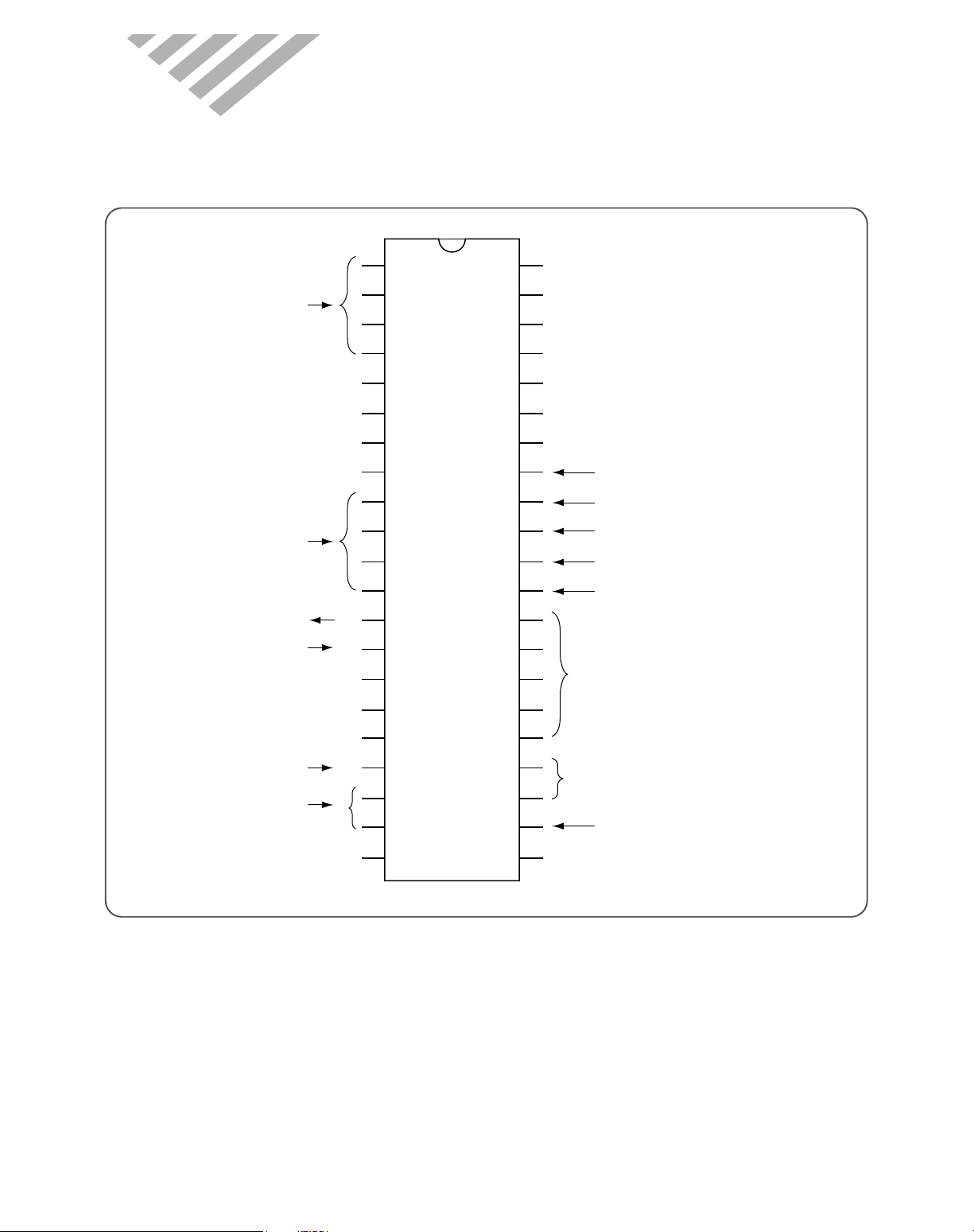
(1) IC1 (MICOM) INDOOR PCB
1
2
3
4
5
6
7
8
9
10
11
12
13
14
15
16
17
18
19
20
21
VDD
(XTOUT)P22
(XTIN)P21
(INT5/STOP)P20
P17
P16
(TC2)P15
(PPG)P14
(DVO)P13
(INT2/TC1)P12
(INT1)P11
(INTO)P10
(AIN7)P67
(AIN6)P66
(AIN5)P65
(AIN4)P64
(AIN3)P63
(AIN2)P62
(AIN1)P61
(AIN0)P60
VAREF
P77(HSO)
P76(HSCK)
P75(SO)
P74(SI)
P73(SCK)
P72(PDO/PWM)
P71( NT4)
P70( NT3/TC3)
P07
P06
P05
P04
P03
P02
P01
P00
TEST
RESET
XIN
XOUT
(VASS)VSS
42
41
40
39
38
37
36
35
34
33
32
31
30
29
28
27
26
25
24
23
22
Steppping Motor
Driving
Buzzer Driving
Communication out
Remocon Input
Communication input
Zero crossing detect
Test S/W Input
Indoor fan motor RPM set
Temperature Sensor Input
LED Driving
Indoor unit
Motor driving
Emergency sw
Reset Curcuit
Oscillation
11. KEY COMPONENTS OF ELECTRONIC CIRCUIT

77
(2) IC1 (MICOM) OUTDOOR PCB
1
2
3
4
5
6
7
8
9
10
11
12
13
14
VDD
HOLD(KEO)
R92(SCK)
R91(SO)
R90(SI)
R83(T1)
R82(INT1)
R81(T2)
R80(INT2)
R63
R62
R61
R60
R53(AIN7)
XOUT
XIN
RESET
R70
R71(PULSE)
R72/VAREF
R40(AINO)
R41(AIN1)
R42(AIN2)
R43(AIN3)
R50(AIN4)
R51(AIN5)
R52(AIN6)
VSS
28
27
26
25
24
23
22
21
20
19
18
17
16
15
Reset circuit
Communication
circuit
Temperature
sensor input
Relay control output
Oscillation

78
(3) U2, 4 (KID65004) DARLINGTON ARRAYS
(4) U8 (KIA7805P) : VOLTAGE REGULATOR (5VDC)
(5) U7 (KIA7812P) : VOLTAGE REGULATOR (12VDC)
IN1 1 16 OUT 1
IN2 2 15 OUT 2
IN 3 3 14 OUT 3
IN 4 4 13 OUT 4
IN5 5 12 OUT 5
IN6 6 11 OUT 6
IN7 7 10 OUT 7
GND 8 9 COMMON FREE
WHEELING DIODES
COMMON
10.5KΩ
7.2KΩ
3KΩ
OUTPUT
GND
INPUT
100K 500
100
100
0 3
10K
6K
500
1K
5K
28K
6K
30pF
2K
5K
200
240
1.4
K
2.7
K
3.3
K
0.19K
INPUT
OUTPUT
GND
SCHEMATIC DIAGRAM
1
2
3
Fin 2 is ground
for Cose 221A.
Case is ground
for Case 1.
10K
INPUT
GND
10K
300
36K
64K
520
26K
60K
29K
20K
20K
40
pF
50K
50 200
300
200
100
16K
210
012
OUTPUT
(Top View)
Pin 1. INPUT
2. GROUND
3. OUTPUT
Pin 1. INPUT
2. GROUND
3. OUTPUT
(Equivalent Circuit)
KID65004AP
(Equivalent Ciircuit)

79
(6) U9 (KIA7042P) : RESET IC
KIA70
42P
OUTLINE
INPUT
GROUND
OUTPUT
VCC
1
3
2
OUT
GND

80
1
IN DO O R U N IT
PROCEDURES PHOTOS
1. Stop the Air conditioner and disconnect the power cord from the wall
outlet.
2. Removing the Insert Grille and Frame Grille. (Fig 1~2)
Draw up the Insert Grille and remove it.
Loosen the screw fixed at the Cover Ter-Block.
Loosen two screw at the Frame Grille.
Remove the Frame Grille.
3. Removing the Control Box. (Fig 3)
Remove room and coil thermistors.
Disconnect the fan motor lead wire from connection at the
Control PCB.
Disconnect the stepping motor lead wire from connection at the
Control PCB.
Remove the select switch from connection at the Control PCB.
Loosen the screw fixed at ground wire.
Remove the Control Box
4. Removing the Drain Pan. (Fig 4)
Disconnect the Body drain hole. (left and right Body)
Disconnect three hook and remove the Drain Pan.
5. Removing the Indoor Evaporator. (Fig 5~6)
Remove the screw fixed at the indoor Evaporator of the Body.
Remove the hook fixed at the Bracket Pipe of the back of Body.
Remove Indoor Evaporator.
6. Removing the Cross Flow Fan. (Fig 7)
Remove set screw fixed at the Motor shaft.
Remove Cross Flow Fan.
7. Remove Motor IDU and Bearing Plastic.
12. DISA SSEMBLY INSTRUC TIO NS
Fig 1
Fig 3
Fig 4
Fig 5
Fig 6
Fig 2
Fig 7
DMB-1822 / 1832LH unit A&B, DMB-2112 / 2122 unit B (9K)

81
PROCEDURES PHOTOS
1. Stop the Air conditioner and disconnect the power cord from the wall
outlet.
2. Removing the Insert Grille and Frame Grille. (Fig 1~2)
Draw up the Insert Grille and remove it.
Loosen two special screws fixed at the Cover Ter-Block.
Loosen three screws at the Body.
Remove the Frame Gille.
3. Removing the Control Box. (Fig 3)
Remove room and coil thermistors.
Disconnect the fan motor lead wire from connection at the
Control PCB.
Disconnect the stepping motor lead wire from connection at the
Control PCB.
Remove the select switch from connection at the Control PCB.
Loosen the screw fixed at the ground wire.
Remove the Control Box
4. Removing the Drain Pan. (Fig 4)
Disconnect the Body drain hole. (left and right Body)
Disconnect three hooks and remove the Drain Pan.
5. Removing the Indoor Evaporator. (Fig 5~6)
Remove three screws fixed at the indoor Evaporator of the Body.
Remove the hook fixed at the Bracket Pipe of the back of Body.
Remove Indoor Evaporator.
6. Removing the Cross Flow Fan. (Fig 7)
Remove set screw fixed at the Motor shaft.
Remove Cross Flow Fan.
7. Remove Motor IDU and Bearing Plastic.
Fig 2
Fig 1
Fig 3
Fig 4
Fig 5
DMB-2112LH unit A (12K)
Fig 6
Fig 7

82
PROCEDURES PHO TOS
1. Stop the Air conditioner and disconnect the power cord from the wall
outlet.
2. Removing the Insert Grille and Frame Grille. (Fig 1~2)
Draw up the Insert Grille and remove it.
Loosen the screw fixed at the Cover Ter-Block.
Loosen two screw at the Frame Grille.
Remove the Frame Grille.
3. Removing the Control Box. (Fig 3)
Remove room and coil thermistors.
Disconnect the fan motor lead wire from connection at the
Control PCB.
Disconnect the stepping motor lead wire from connection at the
Control PCB.
Remove the select switch from connection at the Control PCB.
Loosen the screw fixed at ground wire.
Remove the Control Box
4. Removing the Drain Pan. (Fig 4)
Disconnect the Body drain hole. (left and right Body)
Disconnect three hook and remove the Drain Pan.
5. Removing the Indoor Evaporator. (Fig 5~6)
Remove the screw fixed at the indoor Evaporator of the Body.
Remove the hook fixed at the Bracket Pipe of the back of Body.
Remove Indoor Evaporator.
6. Removing the Cross Flow Fan. (Fig 7)
Remove set screw fixed at the Motor shaft.
Remove Cross Flow Fan.
7. Remove Motor IDU and Bearing Plastic.
Fig 1
Fig 3
Fig 4
Fig 5
Fig 6
DMB-2122LH unit A (12K)
Fig 2
Fig 7

83
PROCEDURES PHOTOS
1.Stop the air conditioner and disconnect the wire from indoor unit to out
door unit.
2. Disassemble the case. (Fig 1~2)
1 Remove the Top Panel. (Loosen nine screws)
2 Remove the Service Cover (Loosen two screws)
3Remove the Front Cabinet. (Loosen se ven scre ws)
4Remove the Side Cabinet.(Loosen eight screws)
5Remove the Guide Post. (Loosen f our screws)
3. Removing the Propeller Fan. (Fig 3)
1Loosen the screw fixed at the motor brack et.
2Remove the Plain W asher .
3Remove the Propeller F an.
4. Removing the panel control. (Fig 4)
1Disconnect the wire at the control panel.
2Loosen the screw at the panel control.
3Remove the parts on the panel control.
5. Removing the partition panel. (Fig 5)
1Loosen four screws at the brack et motor.
2Disconnect the wire at the control panel.
6. Remove the compressor . (Fig 6)
1Remove the condenser
2Loosen three volts at compressor.
3Remove the compressor .
Fig 1
Fig 2
Fig 3
Fig 5
Fig 4
Fig 6
2
OUTDOOR UNIT

84
3
EX P LO DED DIA G R A M (Ind o or U n it)
DMB-1822LH, DMB-2112/2122LH unit B (9K)

85
DMB-1822LH, DMB-2112/2122LH unit B (9K)
No PART CODE PART NAME Q'TY SPEC REMARK
1 3100400301 BODY 1 HIPS T2.0
2 3108008700 MOTOR IDU 1 YDK-8-4B
3 3101500400 CUSHION MOTOR 2 CR I.D 30
4 3106400200 BEARING PLASTIC 1 O.D37.0 x I.D 6.0
5 3100053700 FAN CROSS FLOW ASS'Y 1 P90.0xL540
6 7485401012 SET SCREW 1 6S-4x10-E MFZN
7 3103002601 HOLDER MOTOR 1 HIPS T2.0
8 3102501210 GUIDE EVA 1 PVC L536 * T0.7
9 3110050800 EVAPORATOR ASS'Y 1 DSB-070L
10 3100603800 BRACKET PIPE 1 HIPS T2.0
11 3108100800 PAN DRAIN 1 HIPS T2.0
12 3106501600 BLADE VERTICAL 3 P.P. T1.5
13 3108003900 MOTOR STEPPING 1 MP24GA
14 3107600400 FLAP 1 HIPS T2.5
15 3101404800 COVER WIRE L 1 HIPS
16 3101404900 COVER WIRE R 1 HIPS
17 3100054202 LED PCB ASSÕY 1 091L/LH
18 3100901600 CAP RUBBER 1 SILICON
19-1 3100508400 CONTROL BOX 1 P.P.+G.F.20%
19-2 5EPV050120 TRANSFORMER 1 DWA-220B
19-3 3106900300 CAPACITOR SH. M. B 1 1.0uF 400VAC
19-4 3114302100 CONTROL PCB ASS'Y 9K 1 DMB-1822LH UNIT A
19-5 3108914100 TERMINAL BLOCK 1 JXO-CH-3P
19-6 3104896300 SENSOR ID ASS'Y 1 PTM-KD-43C-D2
19-7 3112716200 HARNESS EARTH 1 UL1015 16 x L200
19-8 7111301611 SCREW TAPPING 2 T1S PAN 3x16 MFZN
20 3100400401 BODY-TOP 1 HIPS T2.0
21 3102200800 FRAME GRILLE 1 HIPS T2.5
22 3104508700 PLATE LED 1 PC SHEET T0.2
23 3104510200 PLATE SWITCH 1 PC SHEET T0.2
24 3101404600 COVER TERMINAL BLOCK 1 HIPS T2.0
25 3102200900 FILTER FRAME 2 P.P. T2.0
26 3102402200 INSERT GRILLE 1 HIPS T2.5
27 3101403900 COVER LED 1
ABS(TRANSPARENCY) T2.0
28 3104507200 PLATE MOUNTING 1 SGCC 1 T0.7
29 3101203000 CLAMP WIRE 1 P.P.+G.F.20%
30 7S422X40B1 SPECIAL SCREW 7
TTS TRS SE 4x12 MFZN
31 7112400611 SCREW TAPPING 4 T1 TRS 4x6 MFZN
32 7141400811 SCREW TAPPING 2 T2 PAN 4x8 MFZN
33 7122401211 SCREW TAPPING 1 T2S TRS 4x12 MFZN
✔ Caution:
In this Service Manual, some parts can be changed for improving, their performance without notice in the parts list. So, if you need the
latest parts information, please refer to PPL(Parts Price List) in Service information Center(http://svc.dwe.co kr)

86
DMB-2112LH unit A (12K)

87
DMB-2112LH unit A (12K)
No PART CODE PART NAME Q'TY SPEC REMARK
1 3100400201 BODY 1 HIPS T2.0
2 3108008800 MOTOR IDU 1 YDK-8-4B/A
3 3101500400 CUSHION MOTOR 2 CR I.D 30
4 3106400200 BEARING PLASTIC 1
O.D37.0 x I.D 6.0
5 3100014400 FAN CROSS FLOW ASS'Y 1 SAN+G. F30%
6 7485401012 SET SCREW 1 6S-4 X 10-E MFZN
7 3110065500 EVAPORATOR ASS'Y 1
8 3108100401 PAN DRAIN 1 HIPS T2.0
9 3106500900 BLADE VERTICAL 12 HIPS T1.8
10 3106300800 BAR BLADE 2 HIPS T1.6
11 3100700800 BUSHING L 1 T1.0
12 3100700700 BUSHING R 1 T1.0
13 3107600400 FLAP 1 HIPS T2.5
14 3108003900 MOTOR STEPPING 1 MP24GA or GSP-24SW
15 3110055300 CONTROL BOX ASS'Y 1 BUYER
15-1 3100503101 BOX CONTROL 1 ABS(VO)-BLACK T2.0
15-2 5EPV050100 TRANS FORMER 1 DWA220A-50/60Hz
15-3 3106900310 CAPACITOR SH.M.B 1 1.0uF 400VAC
15-4 3114302110 CONTROL PCB ASS'Y 12K 1 DMB-2112/2122LH(12K, unit A)
15-5 3104301600 LED PCB ASS'Y 1 DSB-122L/LH
15-6 3108914100 TERMINAL BLOCK 1 JXO-CH-3P
15-7 3104896300 SENSOR I.D ASS'Y 1 PTM-KD43C-D2
✔ Caution:
In this Service Manual, some parts can be changed for improving, their performance without notice in the parts list. So, if you need the
latest parts information, please refer to PPL(Parts Price List) in Service information Center(http://svc.dwe.co kr)

88
No PART CODE PART NAME Q'TY SPEC REMARK
15-8 3102797910 HARNESS I/D EARTH 1 I.D EARTH
15-9 3103400300 KNOB RESET SWITCH 1 ABS T2.5
15-10 3112703500 HARNESS SELECT S/W 1 MODE SELECT
15-11 7111301611 TAPPING SCREW 2 T1S PAN 3 X 16 MFZN
16 3102200401 FRAME GRILLE 1 HIPS T2.5 BUYER
17 3103600300 LAMP INDICATE 1 ABS T1.5
18 3105500500 WINDOW SENSOR 1 ACRIL HI-855M
19 3100801100 CAP FRAME L 1 HIPS 15749 T2.0
20 3100801000 CAP FRAME C 1 HIPS 15749 T2.0
21 3100800900 CAP FRAME R 1 HIPS 15749 T2.0
22 3101401701 COVER TER-BLOCK 1 HIPS T2.0
23 3101901300 FILTER ELECTRO ASS'Y 1 WHITE
24 3101901200 FILTER CARBON ASS'Y 1 BLACK
25 3100017700 FILTER PRE ASS'Y 2 P.P T2.0
26 3108402400 REMOCON ASS'Y 1 LH(English) BUYER
27 3102401500 INSERT GRILLE 1 HIPS T3.0
28 3100602400 BRACKET PIPE 1 HIPS T2.0
29 3101201200 CLAMP BRACKET PIPE 1 HIPS T2.5
30 3104503900 PLATE MOUNTING 1 SBHG1 T0.7
31 3106001600 SPECIAL SCREW 1
T2 4 X 16 MFNI LOCKING
32 7S422X40B1 SPECIAL SCREW 12
TT2 TRS SE 4x12 MFZN
NO 15, 16, 26 Will be changed depend on export destination & buyer requirements.
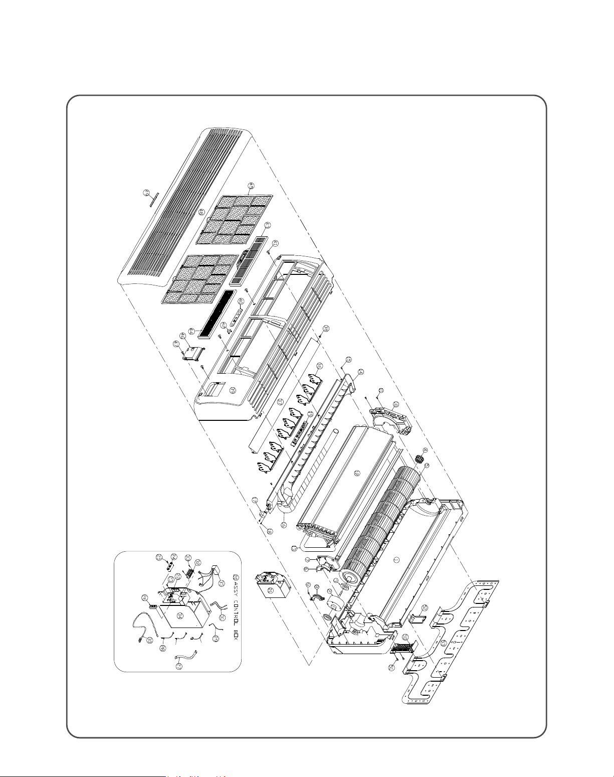
89
DMB-2122LH unit A

90
DMB-2122LH unit A
No PART CODE PART NAME Q'TY SPEC REMARK
1 3110400300 BODY 1 HIPS T2.0 (GY171A)
2 3110078100 MOTOR IDU ASSY 1 ASSY
3 3118003500 MOTOR IDU 1 RB13B(220V, 50/60V)
4 3106400200 BEARING PLASTIC 1 O.D37.0 x I.D 6.0
5 3110046000 FAN CROSS FLOW ASS`Y 1 SAN+G.F 30% 100xL615
6 3113000400 HOLDER MOTOR L 1 HIPS T2.0
7 7172401211 SPECIAL SCREW 2 TT2 TRS 4*12 MFZN
8 3113000500 HOLDER MOTOR R 1 HIPS T2.0
9 7172401211 SPECIAL SCREW 1 TT2 TRS 4*12 MFZN
10 3114503300 PLATE EVAP. L 1 PP T2.0(GY176A)
11 7172401211 SPECIAL SCREW 2 TT2 TRS 4*12 MFZN
12 3110054100 EVAPORATOR 1 ASSY (3R-3C, FPI=1.5)
13 3113309800 PIPE ARTRON HOSE 1 O.D 32X I.D 20 T=6, F-PE
14 3118100500 PAN DRAIN 1 HIPS T2.0(GY176A)
15 7172401211 SPECIAL SCREW 2 TT2 TRS 4*12 MFZN
16 3103210010 HOSE DRAIN ASSY 1 ASSY
17 3108003910 MOTOR STEPPING 1 MP24GA
18 7141400811 SCREW TAPPING 2 T2 PAN M4x8 MFZN
19 3104301700 LED PCB ASS`Y 1 DSB-123L/LH/PH
20 3110063650 CONTROL BOX ASS'Y 1 DMB-2122LH UNIT A
21 3110504000 CONTROL BOX 1 HIPS T2.0 (BLACK)
22 3101204600 CLAMP POWER CORD 1 DA-4N
23 7172401211 SPECIAL SCREW 1 TT2 TRS 4*12 MFZN
24 3111200800 CLAMP WIRE 1 HIPS T2.0 (BLACK)
25 7172401211 SPECIAL SCREW 1 TT2 TRS 4*12 MFZN
26 3114503900 PLATE EARTH 1 SGCC T1.0x26xP46
27 3112716100 HARNESS LED PCB 1 UL1007 #26x7x270
28 3112709500 HARNESS ID POWER 1 UL1015 #20x2x120 (BLU/BRN)
29 3112716200 HARNESS EARTH 1 UL1015 #16x200(YEL/GRN)
30 3112708500 HARNESS SIGNAL 1 1 UL2464 #24x5x6000(WHT)
31 3104896300 SENSOR I/D ASSY 1
32 3108914100 TERMINAL BLOCK 1 JXO-CH-3P
✔ Caution:
In this Service Manual, some parts can be changed for improving, their performance without notice in the parts list. So, if you need the
latest parts information, please refer to PPL(Parts Price List) in Service information Center(http://svc.dwe.co kr)

91
No PART CODE PART NAME Q'TY SPEC REMARK
33 7111301611 SCREW TAPPING 2 T1S PAN 3x16 MFZN
34 3114302110 CONTROL PCB ASS`Y 1 DMB-2112/2122LH(12K, UNIT A)
35 5EPV050120 TRANSFORMER 1 DWA-220B
36 3116501000 BLADE VERTICAL 3 P.P T1.5 (GY176A)
37 3117600100 FLAP 1 HIPS T2.0 (GY171A)
38 3100700700 BUSHING R 1 DSB-123L/LH/PH
39 3112200700 FRAME GRILLE 1 HIPS T2.5
40 3114504200 PLATE LED 1 PC SHEET T0.2
41 7172401211 SPECIAL SCREW 4 TT2 TRS 4*12 MFZN
42 3103401400 KNOB SWITCH 1 DSB-240L/LH
43 3101902610 FILTER ELECTRO ASSY 1 WHITE
44 3101902510 FILTER CARBON ASSY 1 BLACK
45 3111901400 FILTER FRAME 2 P.P T2.0 (BLACK)
46 3111403400 COVER TERMINAL BLOCK 1 HIPS T2.0
47 7S422X40B1 SCREW TAPPING 1 TT2 TRS 4*12 MFZN
48 3112401900 GRILLE INSERT 1 HIPS T2.5 (GY171A)
49 3111403700 COVER LED 1 ABS T2.0
50 3110400200 BODY TOP 1 HIPS T2.0
51 7S422X40B1 SCREW TAPPING 3 TT2 TRS 4*12 MFZN
52 3110603100 BRACKET PIPE 1 HIPS T2.0
53 3114503800 PLATE MOUNTING 1 SGCC T0.8

92
4
EXPLODED DIAGRAM (Outdoor Unit)
DMB-1822/1832LH
5

93
DMB-1822/1832LH
No PART CODE PART NAME Q'TY SPEC REMARK
1 3110055700 BASE PAN ASS'Y 1 SECC T1.2(PAINTING)
2 3102100901 FOOT 2 SECC T1.6
3 3111500400 CUSHION RUBBER 4 NBR 54x63.5
4 3RC0020KM1 COMPRESSOR ASS'Y 1 RBB095M011
5 3RC0020KM1 COMPRESSOR ASS'Y 1 RBB095M011
6 3101500800 COMP. GROMMET 6 DAEWOO
7 3110046800 CONDENSER ASS'Y 1 L568.4 x H575 x W44
8 3112400700 GRILLE COND 1 PP Net 820x570xT3.5
9 3112501000 GUIDE POST ASS'Y 1
10 3114003700 PLATE PARTITION ASS'Y 1 SGCC T0.8
11 3110602700 SUPPORT MOTOR 1 SGCC T1.2
12 3118002400 MOTOR ODU 1 A2919BA010
13 3101800100 FAN PROPELLER 1 ABS+G.F. 10%
14 3110050600 PIPE REVERSING ASS'Y 9K-1 1
15 3110050700 PIPE REVERSING ASS'Y 9K-2 1
16 3110051300 PIPE FILTER ASS'Y 9K-1 1
17 3110051400 PIPE FILTER ASS'Y 9K-2 1
18 3110801300 CABINET SIDE 1 SECC T0.8
19 3110602800 BRACKET SERVICE 1 SECC T1.6
20 3115402000 SERVICE VALVE G (3/8") 2
21 3115402100 SERVICE VALVE L (1/4") 2
22 3101402500 COVER SERVICE 1 ABS
23 3110801200 CABINET FRONT 1 SECC T0.8
24 3112402200 GRILLE DISCHARGE 1 470 P2.5 Steel wire
25 3114203400 PANEL TOP 1 SECC T0.8
26 3103510700 LABEL BRAND 1 PC 346x90xT0.4
27 3110056000 PANEL CONTROL ASS'Y 1
27-1 3110023850 ODU CONTROL PCB ASS'Y 1
27-2 3114203300 PANEL CONTROL 1 SBHG T0.8
27-3
3118800200
TERMINAL BLOCK
1 JXO-CH-2P
3108912320 1 DTB-04P
27-4 3109503210 CAPACITOR DUAL 1 5+25uF 370VAC
27-5 3116903300 CAPACITOR 1 25uF 370VAC
27-6 3101201100 CLAMP CAPACITOR 2 SECC T1.0
27-7 310P9Y00UA SUPPORT PCB 4 DASS-13N
27-8
3101200410
CLAMP CORD
2 DA-3N
3101202400 3 DA-5N
✔ Caution:
In this Service Manual, some parts can be changed for improving, their performance without notice in the parts list. So, if you need the
latest parts information, please refer to PPL(Parts Price List) in Service information Center(http://svc.dwe.co kr)

DMB-2112/2122LH
94

95
DM B -2 1 1 2 / 2 1 2 2 LH
No PART CODE PART NAME Q'TY SPEC REMARK
1 3110055800 BASE PAN Ass`y 1 SECC T1.2(PAINTING)
2 3102100901 FOOT 2 SECC T1.6
3 3111500400 CUSHION RUBBER 4 NBR 54x63.5
4 3RC0020KM1 COMPRESSOR Ass`y 1 RBB095M011
5 3RC0030CM0 COMPRESSOR Ass`y 1 RCB120M001
6 3101500800 COMP. GROMMET 6 DAEWOO
7 3110046900 CONDENSER Ass`y 1 L568.4 x H575 x W44
8 3112400700 GRILLE COND 1 PP Net 820x570xT3.5
9 3112501000 GUIDE POST Ass`y 1
10 3114003700 PLATE PARTITION Ass`y 1 SGCC T0.8
11 3110602700 SUPPORT MOTOR 1 SGCC T1.2
12 3118002400 MOTOR ODU 1 A2919BA010
13 3101800100 FAN PROPELLER 1 ABS+G.F. 20%
14 3110050400 PIPE REVERSING Ass`y 9K 1 Unit B
15 3110050300 PIPE REVERSING Ass`y 12K 1 Unit A
16 3110051600 PIPE FILTER ASSÕY-9K 1
17 3110051500 PIPE FILTER ASSÕY-12K 1
18 3110801300 CABINET SIDE 1 SECC T0.8
19 3110602800 BRACKET SERVICE 1 SECC T1.6
20 3115402000 SERVICE VALVE G (3/8") 2
21 3115402100 SERVICE VALVE L (1/4") 2
22 3101402500 COVER SERVICE 1 ABS
23 3110801200 CABINET FRONT 1 SECC T0.8
24 3112402200 GRILLE DISCHARGE 1 470 ¿2.5 Steel wire
25 3114203400 PANEL TOP 1 SECC T0.8
26 3103510700 LABEL BRAND 1 PC 346x90xT0.4
27 3110056000 PANEL CONTROL Ass`y 1
27-1 3110023850 ODU CONTROL PCB Ass`y 1
27-2 3114203300 PANEL CONTROL 1 SBHG T0.8
27-3
3118800200
TERMINAL BLOCK
1 JXO-CH-2P
3108912320 1 DTB-04P
27-4 3109503210 CAPACITOR DUAL 1 5+25µF 370VAC
27-5 3116903300 CAPACITOR 1 25µF 370VAC
27-6 3101201100 CLAMP CAPACITOR 2 SECC T1.0
27-7 310P9Y00UA SUPPORT PCB 4 DASS-13N
27-8
3101200410
CLAMP CORD
2 DA-3N
3101202400 3 DA-5N
✔ Caution:
In this Service Manual, some parts can be changed for improving, their performance without notice in the parts list. So, if you need the
latest parts information, please refer to PPL(Parts Price List) in Service information Center(http://svc.dwe.co kr)

96
5
CONTROL BOX ASSEMBLY
DMB-1822/1832LH, DMB-2112/2122LH unit B (9K)
L N

97
DMB-1822/1832LH, DMB-2112/2122LH unit B (9K)
No PART CODE PART NAME Q'TY SPEC REMARK
1 3100084000 Control Box 1 P.P+G.F 20%
2 3114302170 CONTROL PCB ASS'Y 9K 1
3 3108914100 TERMINAL BLOCK 1
JXO-CH-3P
4 3106900300 CAPACITOR SH.M.B 1 1.0µF 400VAC
5 3104896300 SENSOR ID ASSÕY 1 PTM-KD43C-D2
6 3104398201 LED PCB 1 110 x 31 x T1.6
7 3112708600 HARNESS SIGNAL 2 1 UL2464 #24x5x6000 (Red)
8 3102797910 HARNESS I/D EARTH 1 I/D EARTH
9 3112709500 HARNESS POWER 1 UL1015 #20/20x120(Blu/Brn)
✔ Caution:
In this Service Manual, some parts can be changed for improving, their performance without notice in the parts list. So, if you need the
latest parts information, please refer to PPL(Parts Price List) in Service information Center(http://svc.dwe.co kr)
 Loading...