

Daewoo DSB-093LH, DSB-183LH User Manual

CONTENTS
1. Specifications..........................................................................................................2
2. Outline and Dimensions....................................................................................... 4
3. Operation .............................................................................................................. 9
4. Wiring Diagram.....................................................................................................23
5. Refrigerant Cycle..................................................................................................27
6. Control Block Diagram .........................................................................................30
7. Trouble Shooting...................................................................................................32
8. Key Components of Electronic Circuit.................................................................54
9. Disassembly Instructions .....................................................................................57
1) Indoor Unit ........................................................................................................57
2) Outdoor Unit .....................................................................................................59
3) Exploded Diagram And Parts List (Indoor Unit)..............................................61
4) Exploded Diagram And Parts List (Outdoor Unit)...........................................65
5) Control Box Assembly And Parts List..............................................................71
Contents
2
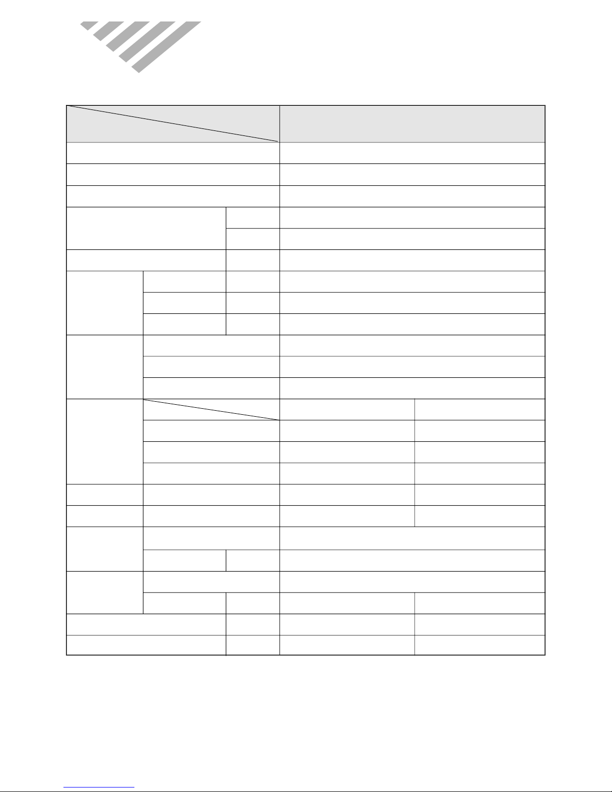
MODEL
DSB-093LH
ITEM
Function Cooling & Heating
Class T1
Power AC 220~240V/ 50Hz
Capacity W 2,930/2,780
Btu/h 10,000/9,500
Dehumidification l/h 1.2
Running Current A 4.8/4.3
Power Input W 1,020/920
Starting Current A 24
Type Rotary
Model RBB100A011
Capacitor 30µF / 370VAC
Indoor Unit Outdoor Unit
Type Cross flow fan Propeller fan
Capacitor 1.5µF 400VAC 1.8µF 400VAC
Motor Model Number RP-13B YDK-35-6B
Sound Level (Hi) dB(A) 39 48
Fan Speed (Hi) RPM 1,200 850
Control Capillary
Charge Q'ty g 730
Type Flare
OD (Liquid/Gas) in(mm) 1/4 (6.35) 3/8 (9.52)
Dimensions (W x H x D) mm 815 x 285 x 195 654 x 549 x 256
Net Weight kg 9.2 34
Electrical
Data
Compressor
Fan
Motor
Refrigerant
(R-22)
Connection
DSB-093LH
1. SPECIFICATIONS
3
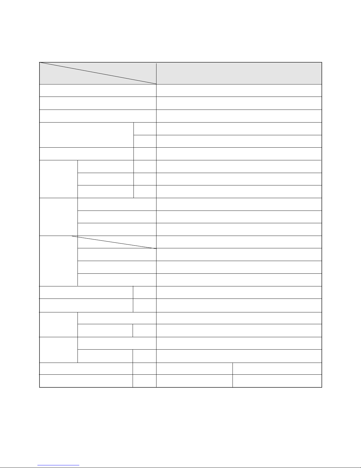
MODEL
ITEM
Function
Class
Power
Capacity
Btu/h
Dehumidification l/h
Running Current A
Power Input W
Starting Current A
Type
Model
Capacitor
Type
Capacitor
Motor Model Number
Sound Level (Hi) dB(A)
Fan Speed (Hi) RPM
Control
Charge Q'ty g
Type
OD (Liquid/Gas) in(mm)
Dimensions (W x H x D) mm 1080 x 298 x 200 800 x 615 x 320
Net Weight kg 14.7 51.9
Electrical
Data
Compressor
Fan
Motor
Refrigerant
(R-22)
Connection
DSB-183LH
W
DSB-183LH
Cooling & Heating
T1
AC 220~240V/ 50Hz
5,430/5,710
2.5
9.4/9.3
1,930/1,920
41
Rotary
40µF / 450VAC
Indoor Unit
Cross flow fan
2µF 400VAC
IC-9430DWKF7A
43
1,350
Capillary
1,400
Flare
1/4 (6.35)
18,500/19,500
RCB195A001
4
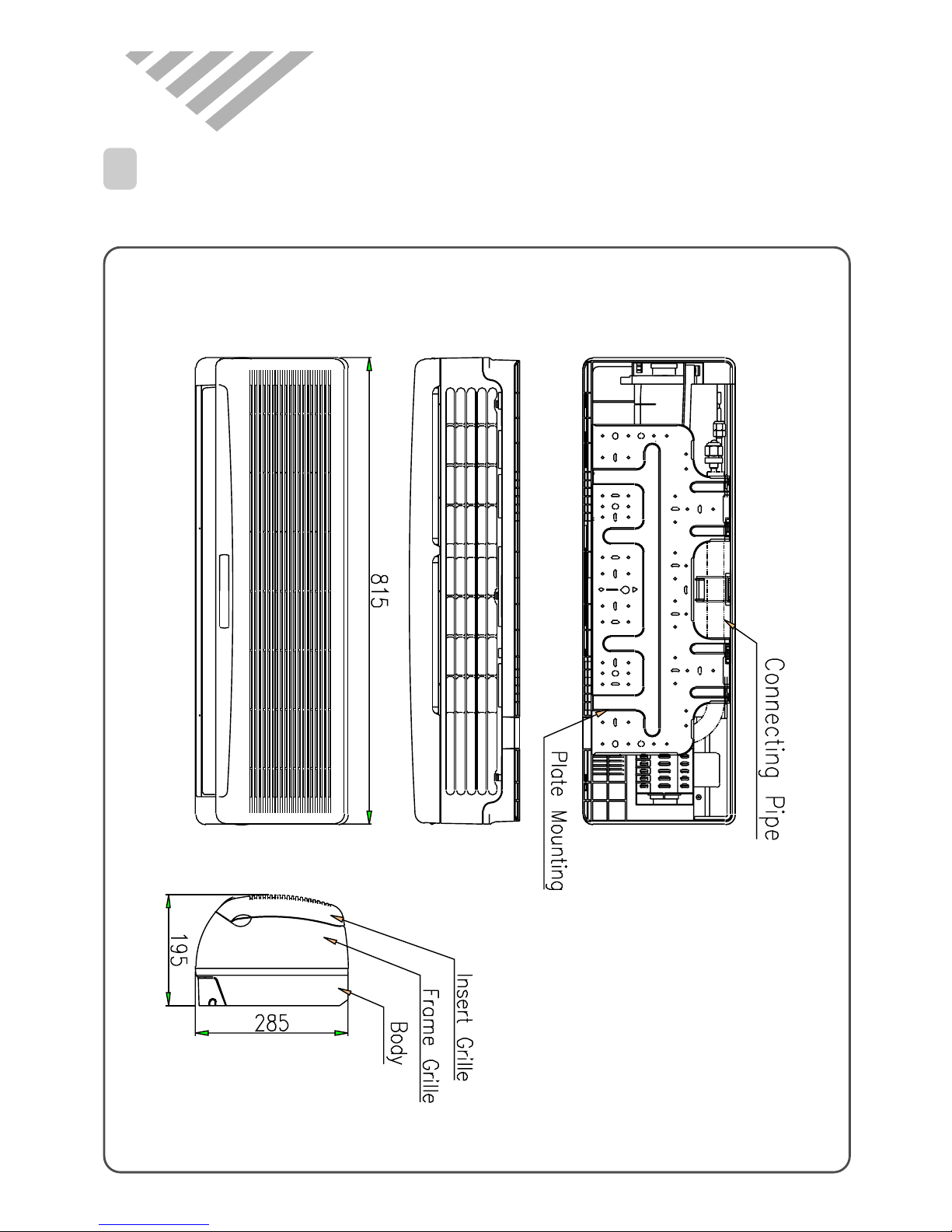
2. OUTLINE AND DIMENSIONS
1 INDOOR UNIT
DSB-093LH
5
Connecting Pipe
Body
Frame Grille
Grille Insert
Plate Mounting
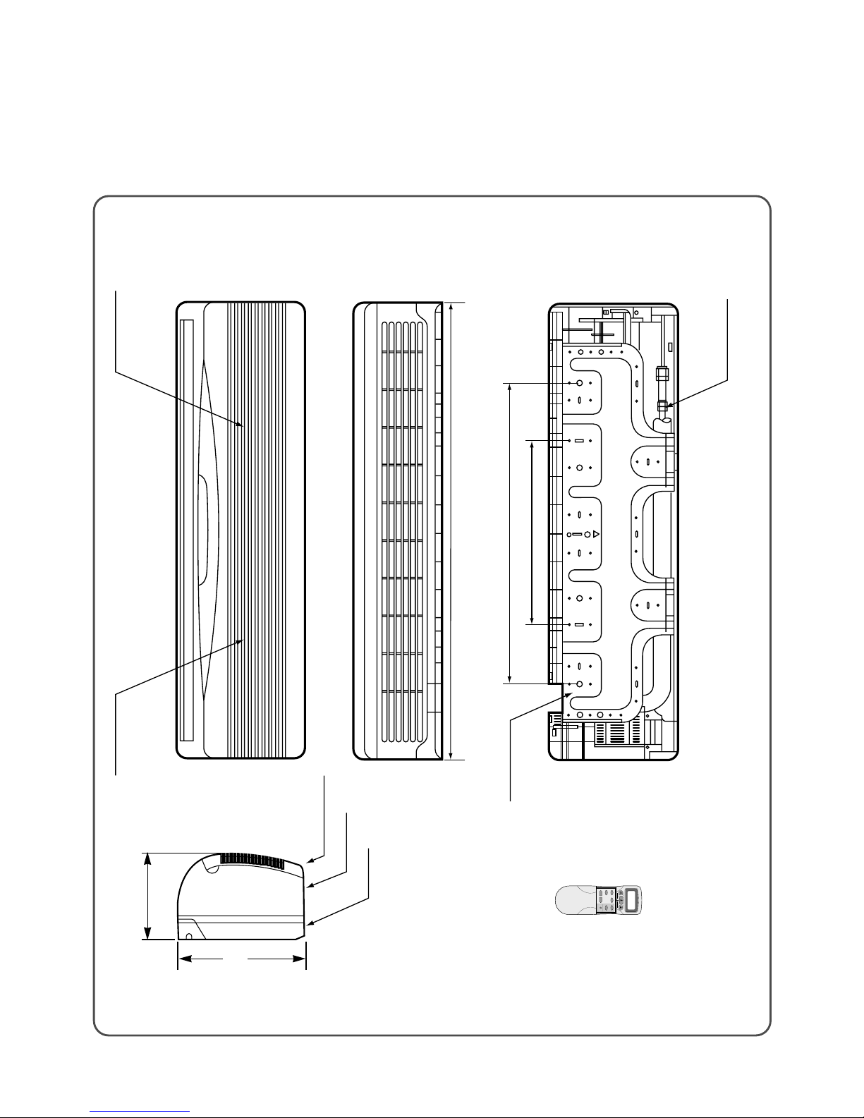
430
710
1080
Filter-L Filter-R
REMOCON
DSB-183LH
200
298
6
Indoor Unit
DSB-183LH
DSB-093LH
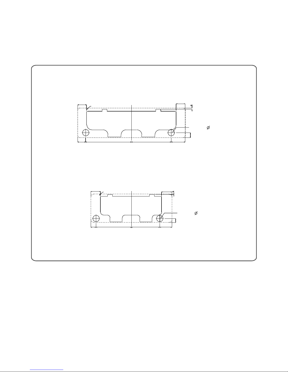
Indoor Unit
Installation Plate
Wall Hole ( 65)
Wall Hole ( 65)
Installation Plate
90
97
53 355 285 122
40
80 460 400 140
50
Unit : mm
INSTALLING THE INSTALLATION PLATE
103
90
7
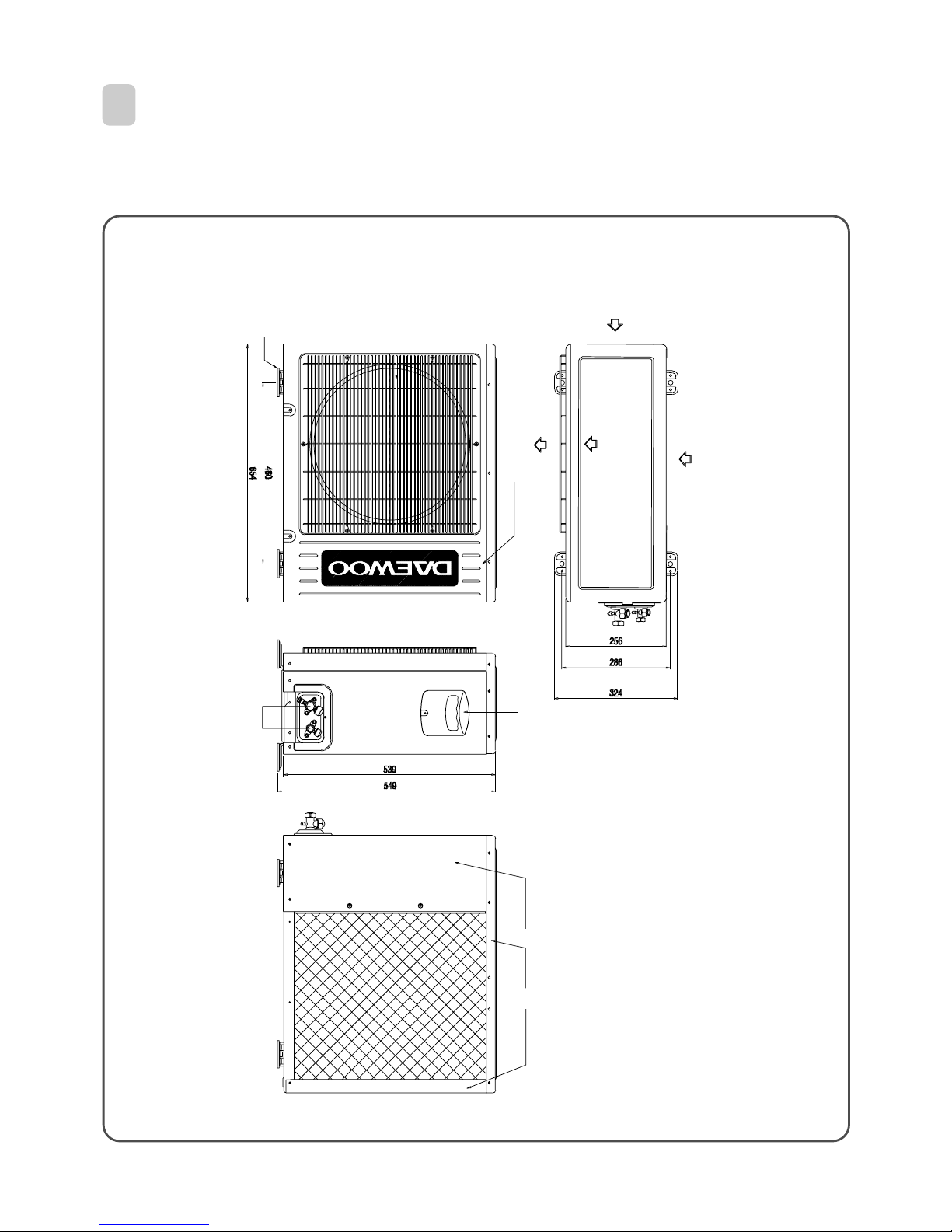
DSB-093LH
Outlet
Foot Cushion
Cabinet Front
Cabinet Side
Panel Top
Guide Support
SVC Cover
Servise Valve
Inlet
Outlet
Inlet
2 OUTDOOR UNIT
8
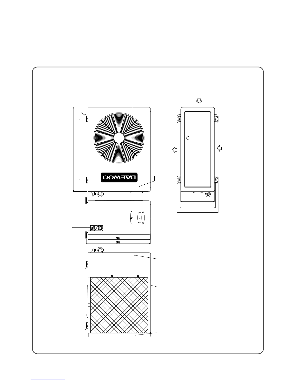
DSB-183LH
Inlet
Outlet
Outlet
Foot Cushion
Cabinet Front
Cabinet Side Panel Top Guide Support
SVC Cover
Servise Valve
580
800
320
360
400
Inlet
1
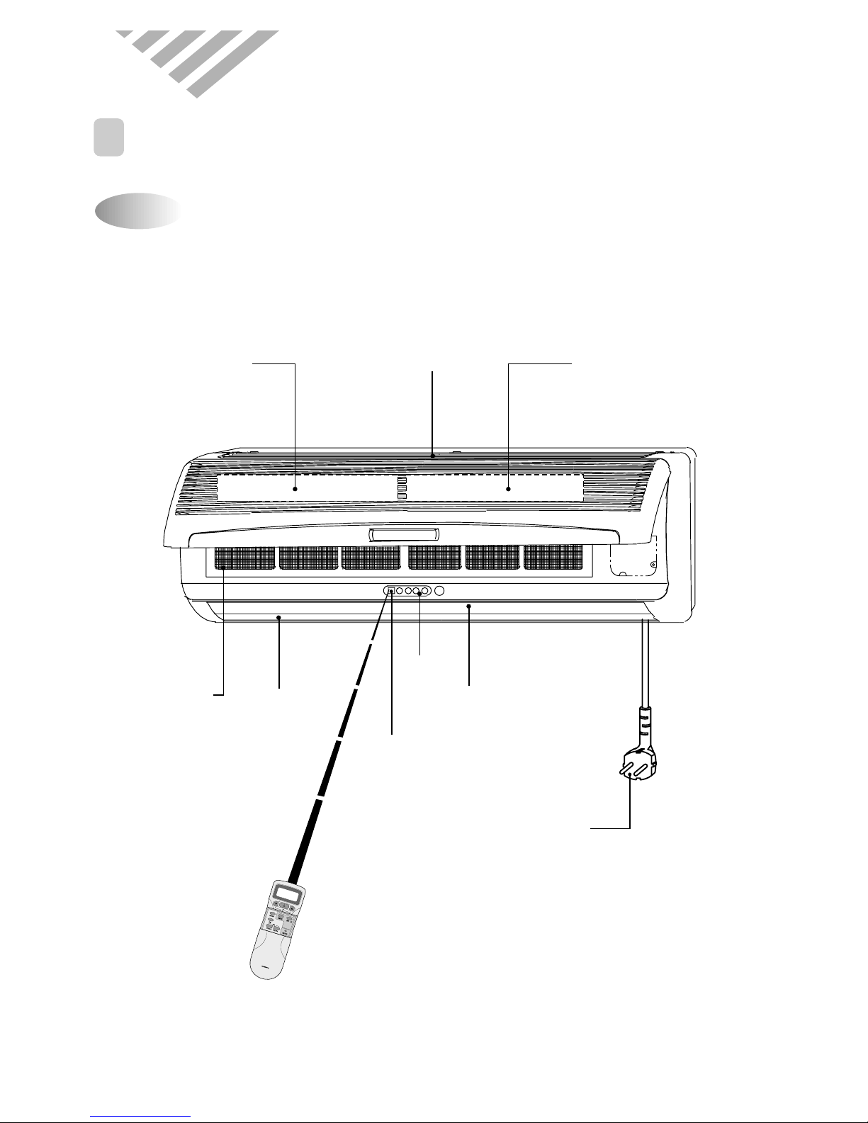
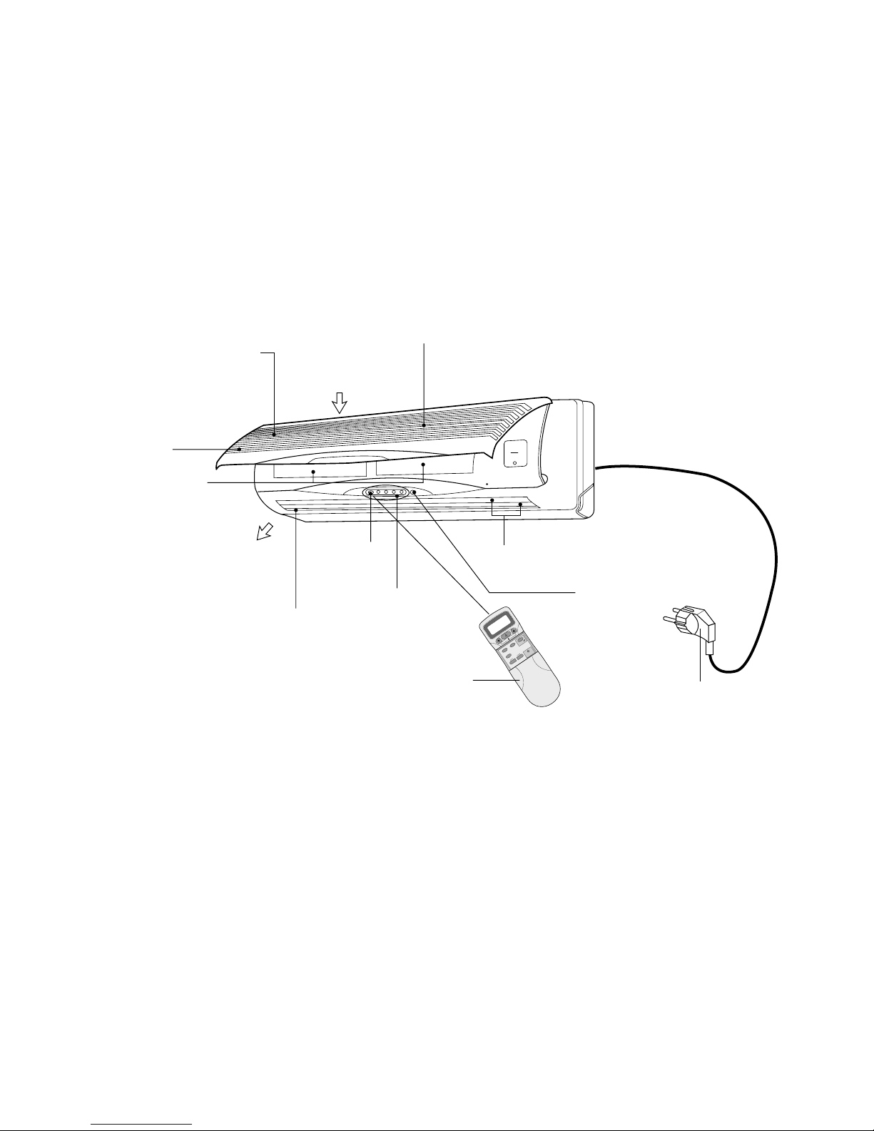
NAME AND FUNCTION OF PARTS
Indoor Unit
3. OPERA TION
DSB-093LH
Power Plug
Electrostatic FilterDeodorizing Filter Air Inlet
Antibacterial
Filter
Air Outlet Fan Direction
(Up, Down)
Remote Controller
Remote
Controller
Receiver
Lamp
R
E
M
O
T
E
C
O
N
T
R
O
L
L
E
R
Removes bad smells
from the air.
Removes dust and
prohibits germs.
Removes dust and
particles from the air
9
10
Indoor Cover
Electrostatic Filter
Removes dust
particles from the air.
Deodorizing Filter
Removes bad
smells from the air.
Emergency/Remote Switch
Indicators
Indicate the
AC setting.
Remote
Sensor
Power Plug
LCD Remote
Controller
Air Cleaning Filters
Removes dust and
prohibits germs.
AIR OUT
AIR IN
Fan Direction
(Up/Down)
Fan Direction
(Left/Right)
M
O
D
E
S
L
E
E
P
O
N
/
O
F
F
T
I
M
E
R
E
N
T
E
R
/
C
A
N
C
E
L
F
A
N
S
P
E
E
D
T
U
R
B
O
/
M
I
L
D
F
A
N
D
I
R
.
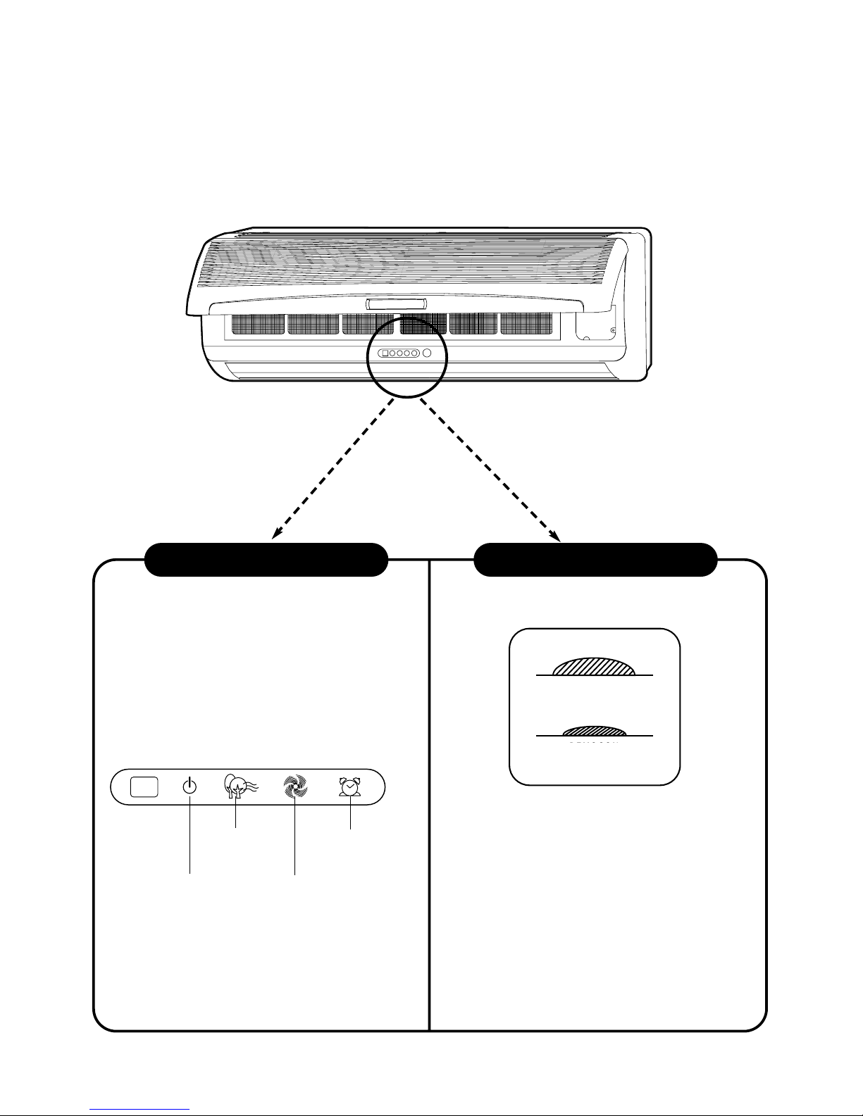
DSB-183LH
DSB-093LH
■ Remote Control Signal Receiver
This place is the part to receive the signal if it receives
the signal, you can hear the signal “beep. beep”.
■There is a switch panel at inside of Front Panel.
At the time of operating, open the Front Panel.
Emergency switch can be used when the remote
controller is lost or Testing.
Remote switch is usually used by remote controller.
Indoor Unit Display Switch Panel
11
ON (Red)
Lights when the
operation is going on.
Air clean
(Green)
Timer (Yellow)
Lights during the time
reservation mode.
Quick (Red)
Lights during the
time Quick
Mode.
EMERGENCY
REMOCON
REMOCON
EMERGENCY
12
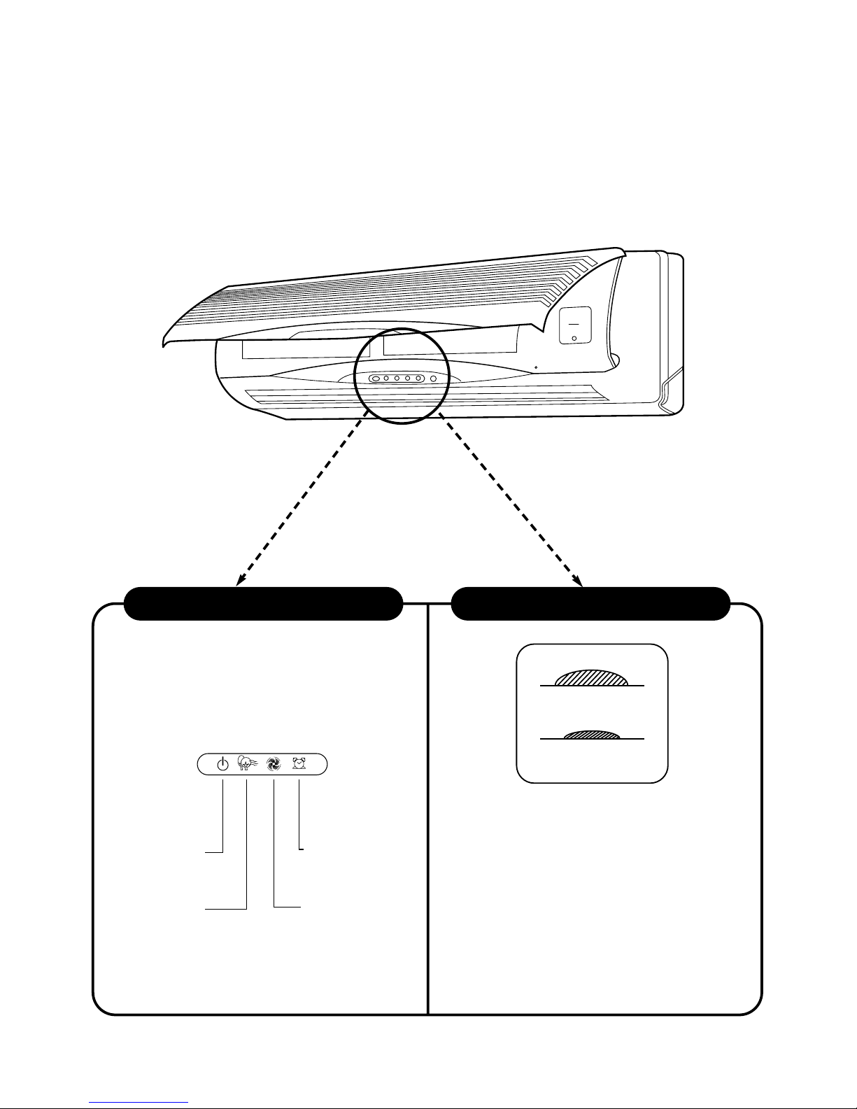
DSB-183LH
■
Remote Control Signal Receiver
This place is the part to receive the signal if it
receives the signal, you can hear the signal
“beep. “beep, beep.”
■
There is a switch panel at inside of
Front Panel. At the time of operating,
open the Front Panel.
Emergency switch can be used when the remote
controller is lost or Testing.
Remote switch is usually used by remote
controller.
Indoor Unit Display Switch Panel
Timer (Yellow)
Lights-on during the time
of reservation mode.
Quick (Red)
Lights-on during the time
of Quick Mode.
ON (Red)
Lights-on
during the operation
Air clean (Green)
Lights-on
during the operation
EMERGENCY
REMOCON
REMOCON
EMERGENCY
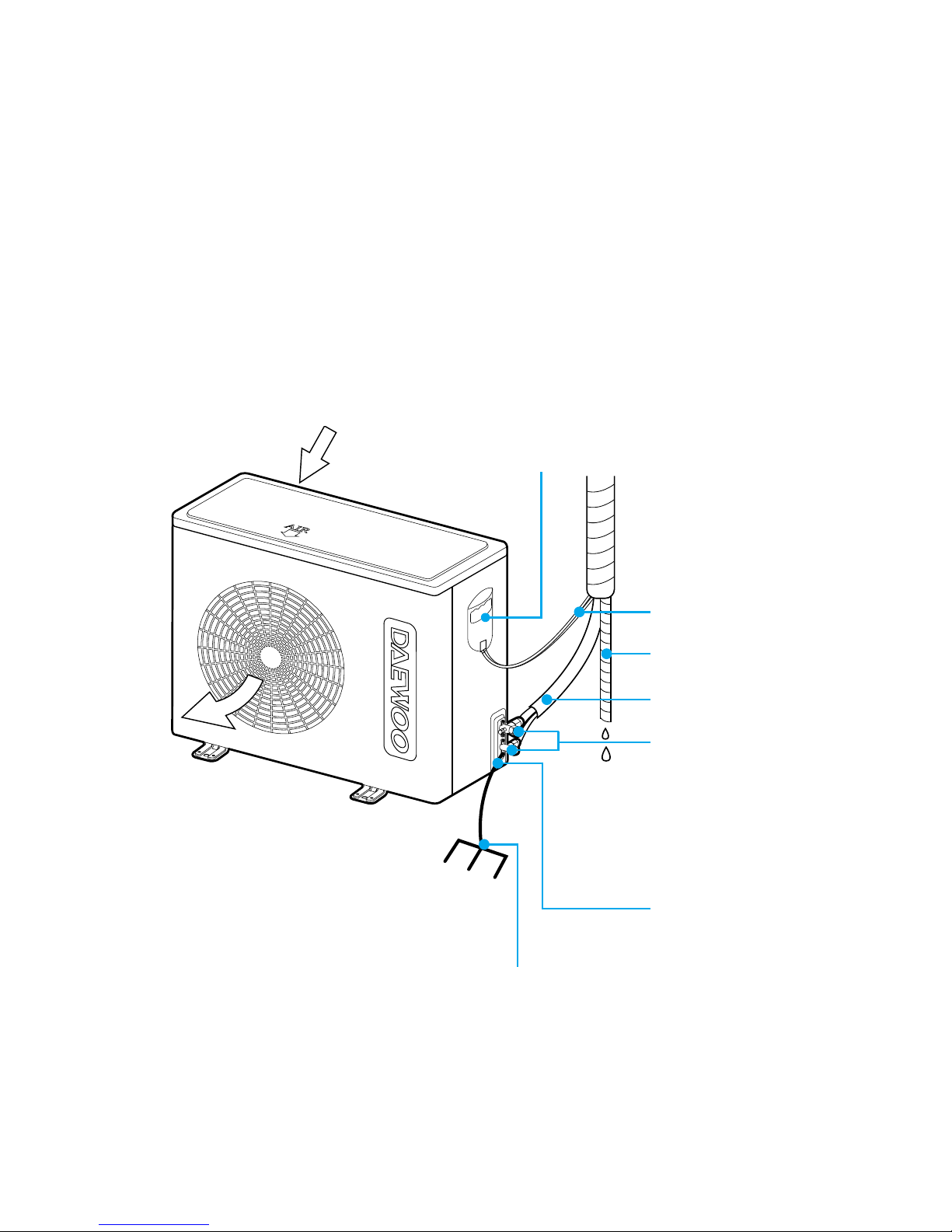
13
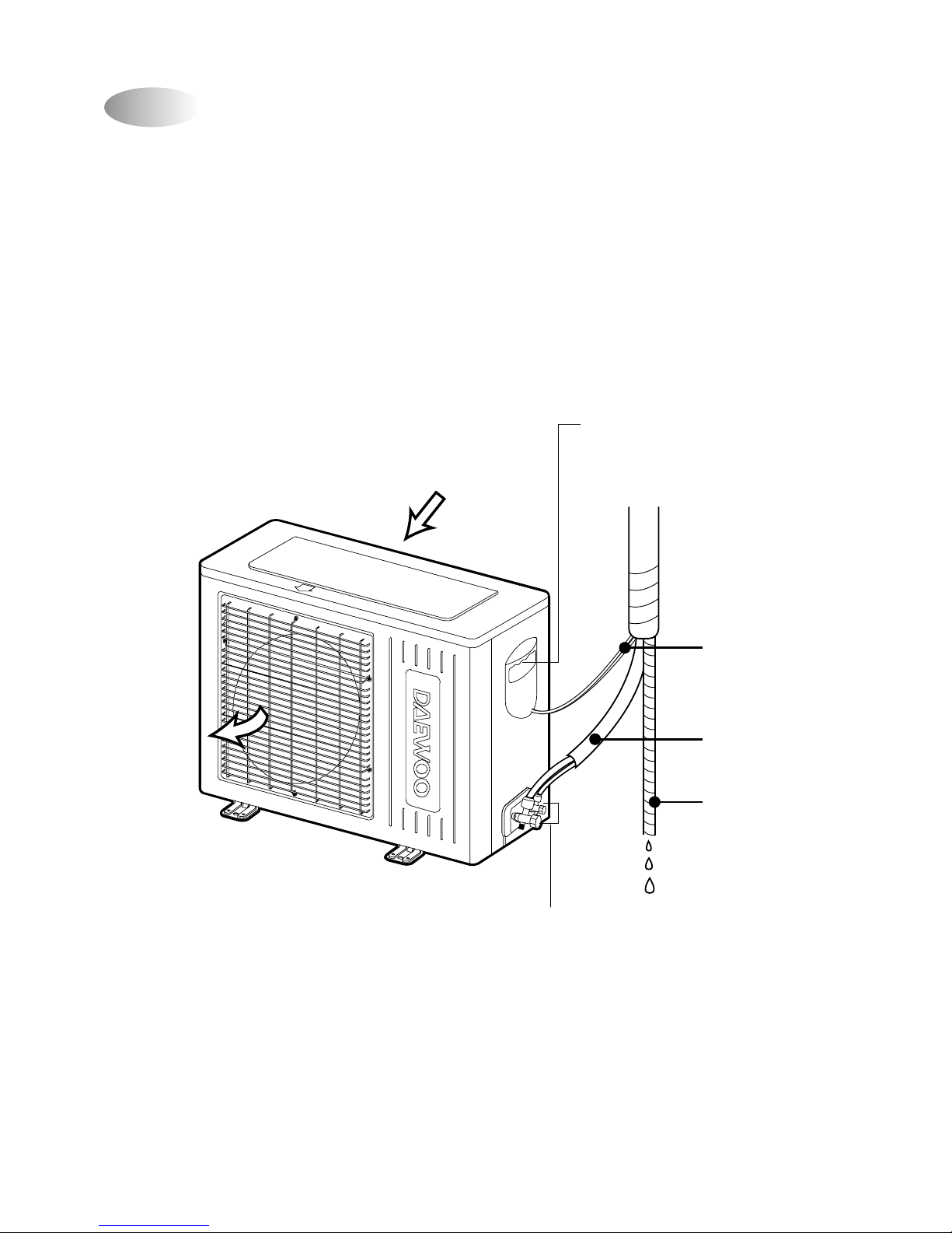
DSB-093LH
Connection Cover
Remove cover to access the
AC connection
to the indoor unit.
Service Valves
The indoor and outdoor units
are connected by copper tubes
which are connected here.
AIR IN
AIR OUT
Connection Wire
Connecting Pipe
Drain Hose
Outdoor Unit
14
DSB-183LH
AIR IN
AIR OUT
AC Cover
Remove cover to
access the AC
connection from
this unit to the
indoor unit.
Connection Wire
Drain Hose
COPPER TUBING
Service Valves
The indoor and outdoor
units are connected by
copper tubes which are
connected here.
Grounding Screw
Ground the unit here.
Ground Wire
(Not supplied)

15
MODE
SLEEP
ON/OFF
TIMER
ENTER/
CANCEL
FAN SPEED
TURBO/MILD
Display
Displays information
pertaining to unit.
TURBO/MILD
Press to select super power
operation(Turbo) mode
TIMER ENTER/CANCEL Button
Press to enter a timer setting or
to cancel timer setting
TIMER ON/OFF Button
Press to set the unit off or on time.
(0.5, 1, 1.5, 2, 2.5, 3, 4, 5, 6, 8,
10, 12, 16, 20, 24hr)
MODE Button
Press to cycle through the modes
(Auto/Quick/Cool/Fan/Dehumidifier/
Heat)
SLEEP Button
Press to set the unit for
the sleep mode.
FAN DIR. Button
Press to select up/down
direction for fan.
FAN DIR. Button
Press to select left/right
direction for fan.
ON/OFF Button
Press to turn the unit
on or off.
TEMPERATURE Buttons
Press to raise or lower
the desired temperature.
FAN SPEED Button
Press to select the fan speed
(High " ", Middle " ", Low " ",
Natural).
COVER
Slide down to access most
of the remote buttons.
Slide down further to
access the battery
compartment.
AUTO
FAN DIR.
FAN DIR.
Name of Each Button
2
REMOTE CONTROLLER
(Option)
16
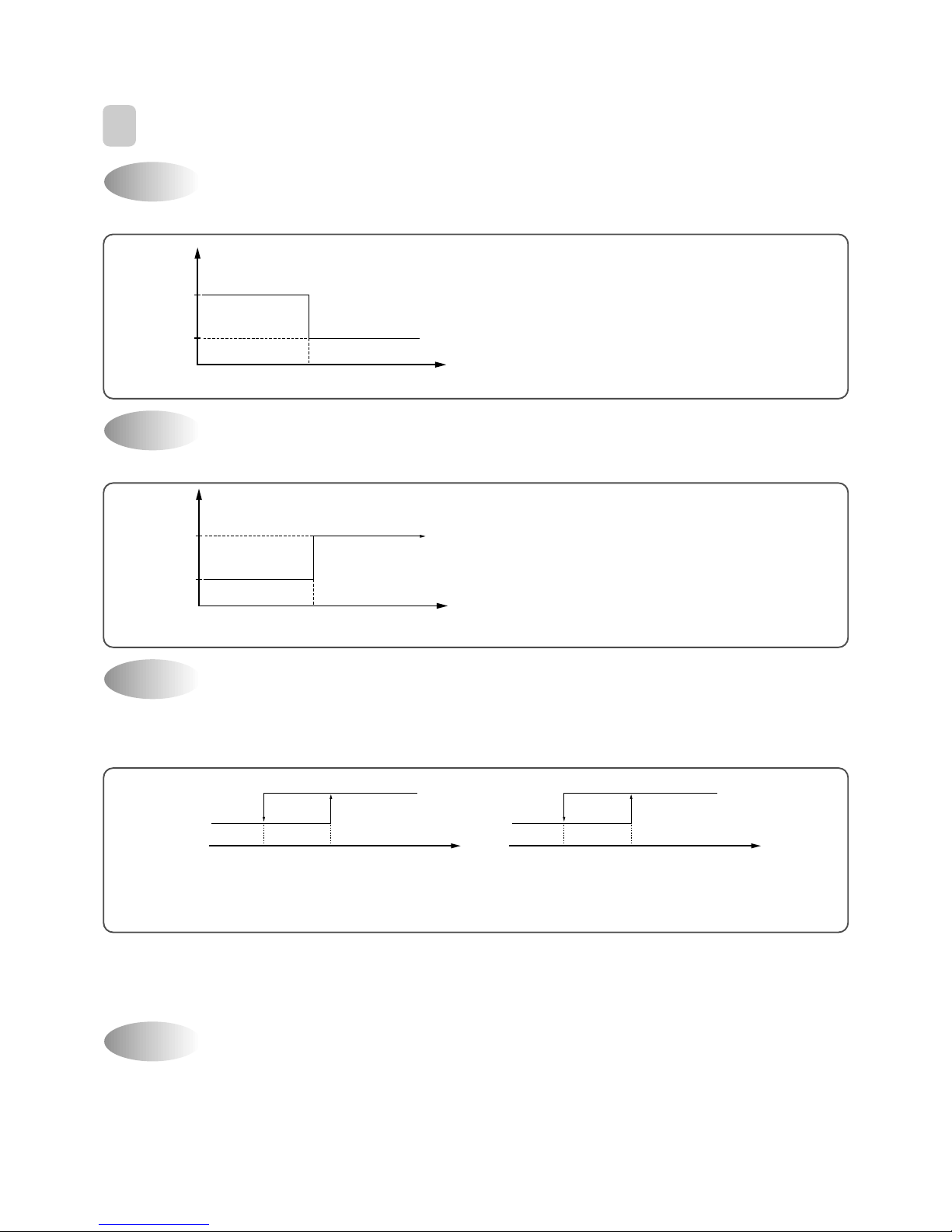
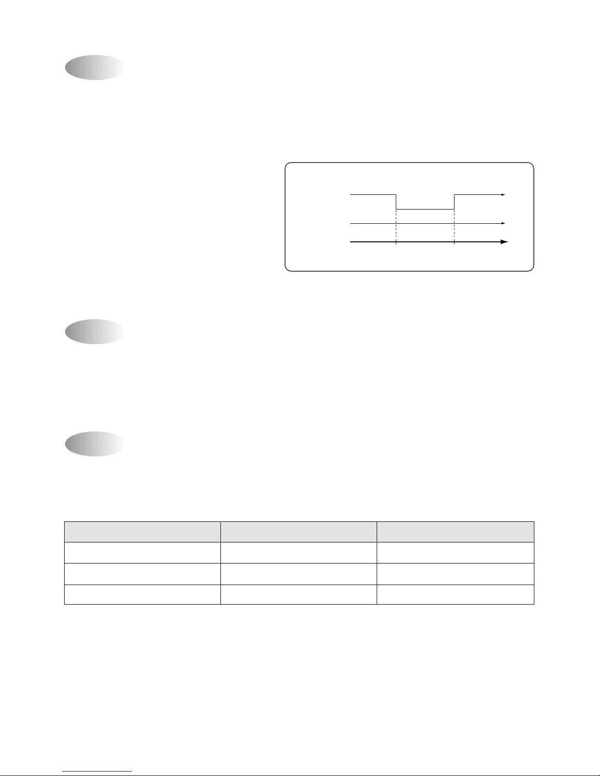
If you set time in OFF-Timer Mode, the unit will stop at the set time.
If you set time in ON-Timer Mode, the unit will run at the set time.
(1) Range of setting temperature: 18~32°C
(2) Setting temperature: Operating temperature of compressor
(3) During the time of test operating, Fan (Indoor , Outdoor) and Compressor is running regardless of room
temperature.
If the Indoor Unit Display receive the signal of Remote Controller , y ou can hear the signal "beep –" or "beep,
beep".
(1) In the case of receiving ON/OFF signal-"beep" "beep"
(2) And so on-"beep"
OFF-Timer
3
DESCRIPTION OF FUNCTIONS
Unit ON
Unit OFF
SET Time
HOUR
ON
OFF
ON-Timer
Unit ON
Unit OFF
SET Time
HOUR
ON
OFF
Control of Room Temperature
Buzzer
COMP (ON)
*RT: ROOM TEMPERATURE
DT: DESIRED TEMPERATURE
COMP (OFF)
-1°C0°C
(COOLING)
(RT-DT)
COMP (OFF)
COMP (ON)
-1°C0°C
HEATING
(RT-DT)
+1°C +1°C
17
Fan Speed (Indoor Unit)
(1) Motor speed (high speed, middle speed, low speed).
(2) Remote controller setting fan speed. (Auto , L, M, H, Natural)
(3) Relation of operating mode between fan speed.
(4) Automatic Operation
If the unit is set in 'AUT O' mode , the unit operates automatically according to the room temperature to keep the
room temperature comfortable.
0°C
L
M
H
1°C2°C
(R.T-D.T)
(D.T)
0°C
L
M
H
1°C2°C
(DT-RT)
(COOLING)
(HEATING)
FAN ONLY COOL
DEHUMI-
AUTO QUICK HEAT
DIFICATION
H HHLHH H
M MMLMH M
L LLLLH L
Auto X Auto L Auto H Auto
Natural Natural Natural L Natural H Natural
18
(1) When the remote controller is lost, damaged or the battery is discharged, the Emergency operation can be
used to run the unit.
(2) The setting conditions of Emergency operation are as follows.
• Operation mode: Quick
• Preset temperature:18°C: Cooling, 32°C: Heating)
• F an speed: High
You cannot operate with remote controller.
(1) When you are going to sleep, select sleep switch and the unit controls the room to the desired temperature.
(The unit will not operate after 4 hour)
(2) F or changing the temperature.
(3) To cancel sleep mode, press the SLEEP button again or press the MODE button once.: the SLEEP
indicator will disappear in the display.
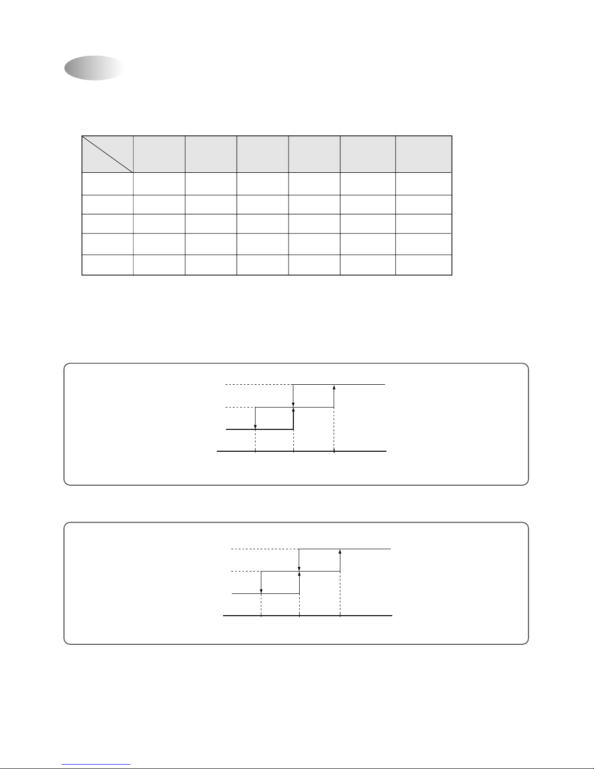
Sleep Mode
Indoor Fan Motor RPM for each Models
Emergency Operation
0 0.5 1.0 HOUR
(COOLING CYCLE)
DT
+0.5°C
+0.5°C
+0.5°C
0 0.5 1.0 HOUR
(HEATING CYCLE)
DT
–0.5°C
–0.5°C
–0.5°C
Model Group
(kBtu)
7K/9K COOL
7K HEAT
9K HEAT
DSB-093LH
12K COOL/HEAT
18K COOL/HEAT
24K COOL/HEAT
High (5)
1350
1200
1300
1200
1350
1350
1350
Mid (4)
1280
X
X
X
1280
1280
1280
Low=High (3)
1200
1100
1250
1100
1200
1200
1200
Mid (2)
1100
X
X
X
1100
1100
1100
Low (1)
1000
1000
1200
1000
1000
1000
1000
Monitoring
500
500
500
500
500
500
500
TURBO MILD
19
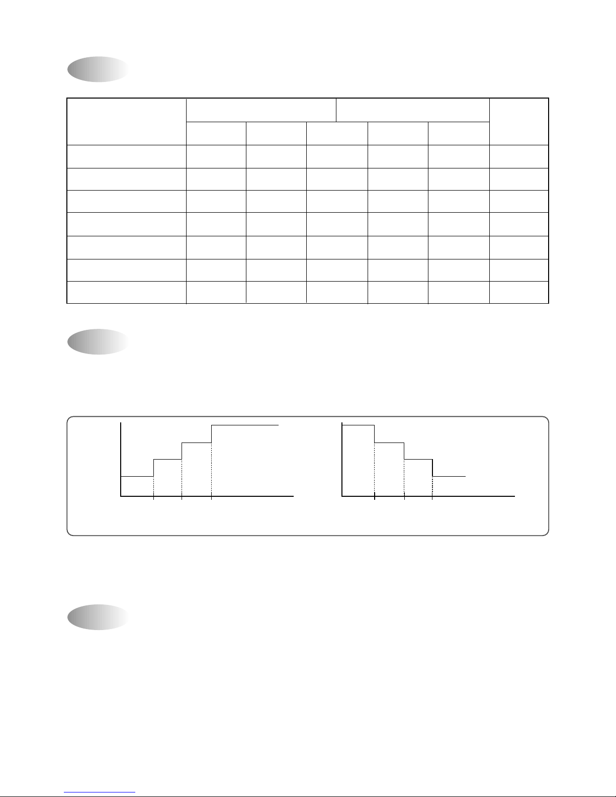
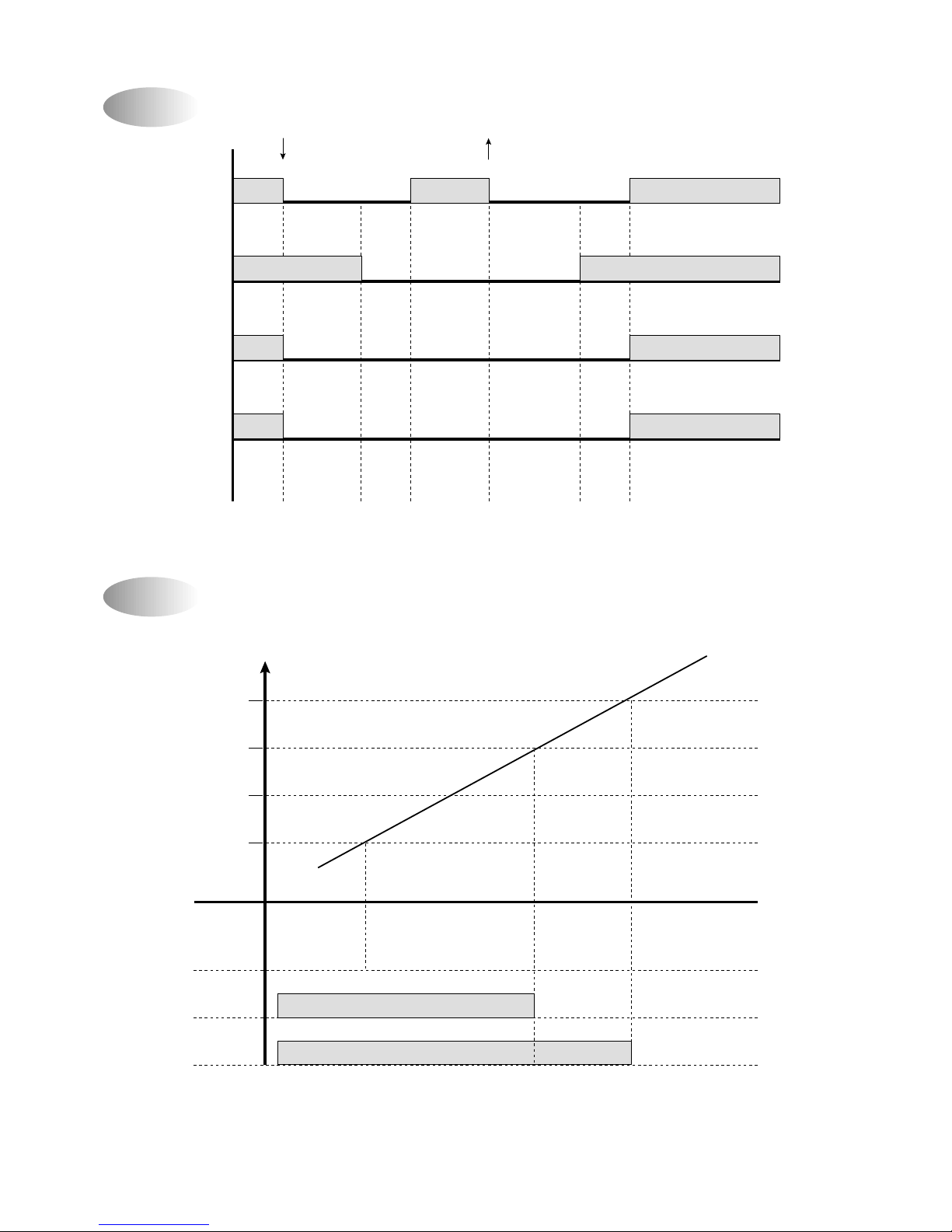
Frost Prevention of Indoor Unit
When the unit operates at low ambient temperature, frost may appear on the Ev aporator. When the indoor coil
temperature is lower than 0°C at the end of 10 minutes of continuous compressor operation from the start, the
microcomputer of the unit stops the compressor to protect the unit from the frost. The control procedure for
indoor coil freeze protection.
1) The compressor and outdoor fan turn off.
2) Indoor fan operates according to user set speed.
3) The normal operation returns when the indoor coil
temperature is higher than 7°C or equal to 7°C.
-1°C+7°C
Compressor and
Outdoor Fan
ON ON
OFF
Indoor Fan
Set speed
(Indoor coil temperature)
Auto Mode
(1) In Auto Mode
After the indoor fan is operated f or 20 seconds in the Auto Mode the unit will operate automatically b y selecting
operating Mode according to the room temperature
(2) Selecting Operating Mode Again
Room temperature meets desired temperature and the compressor stops running over 30 minutes, then the unit
selects operating Mode again.
3 min. Time Delay of Compressor
In normal operation, there is a time delay of three minutes between turn off and turning back on including initial
power up.
ROOM TEMPERATURE
DT-2°C RT
DT-2°C
≤
RT ≤DT+3°C
DT+3°C RT
OPERA TING MODE
Heating
Dehumidifier
Cooling
FLAP POSITION
Heating Position
Cooling Position
Cooling Position
(RT: Room temperature)
>
<
20
1) Cooling Mode
When the room temperature is higher than 22C
Fan Speed: Super high speed
Air discharge direction: Fixed
Set temperature: 18 C (Fixed)
Compressor and Outdoor Fan
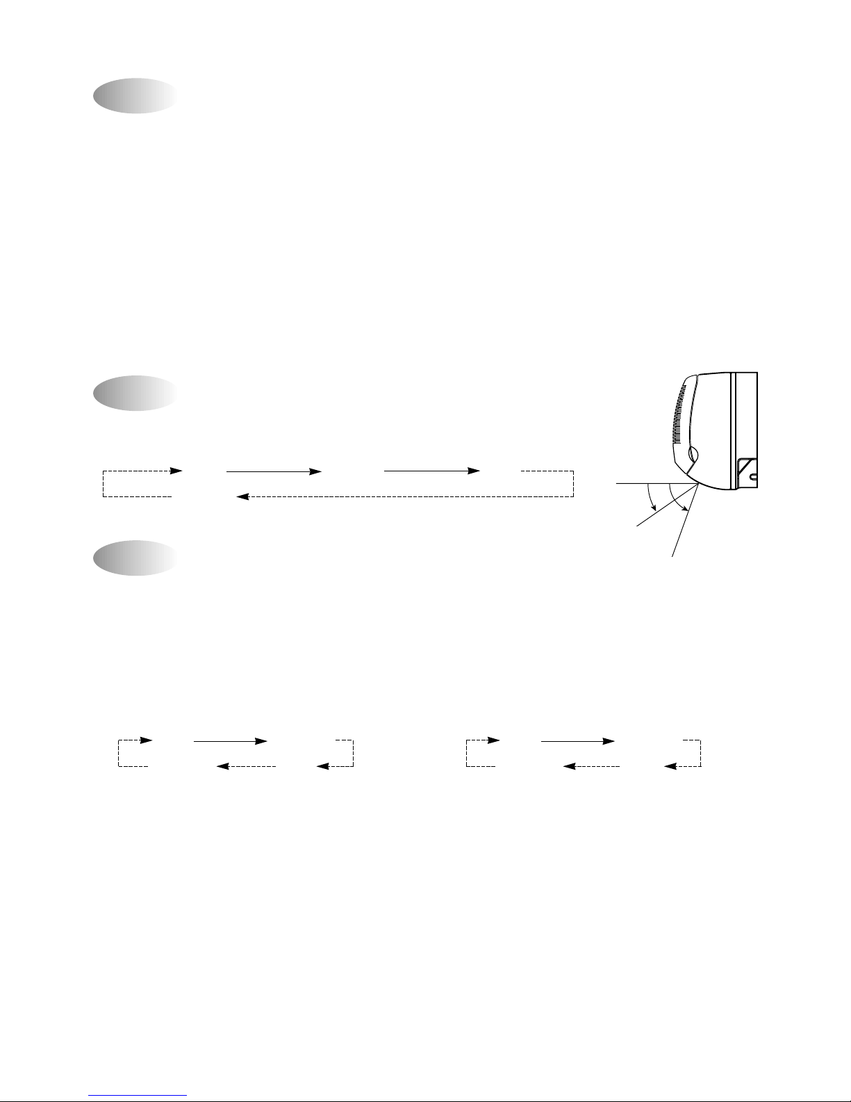
The air discharge direction procedure is below
Fixed Up/Down
Up/Down Fixed
The option is LEFT/RIGHT direction.
1) Heating Mode
When the room temperature is higher than 22C
Fan Speed: Super high speed
Air discharge direction: Fixed
Set temperature: 18 C (Fixed)
Compressor and Outdoor Fan
The air discharge direction procedure is below
Fixed Up/Down
Up/Down Fixed
The option is LEFT/RIGHT direction.
Dehumidification Mode
Air Discharge Direction (only remocon operation)
Quick Mode (Powerful Cooling & Heating)
The air discharge direction procedure is below.
Fixed Up/Down Fixed
Up/Down
Desired temperature < Room temperature
Outdoor Fan, Compressor : ON
Indoor Fan : Low speed
Desired temperature Room temperature
Compressor : 3 min/ON, 5 min/OFF
Fan Speed : low speed
Room temperature 18 C
Compressor : OFF
Fan speed : Low speed
COOLING POSITION
HEATING POSITION
>
=
<
=
21
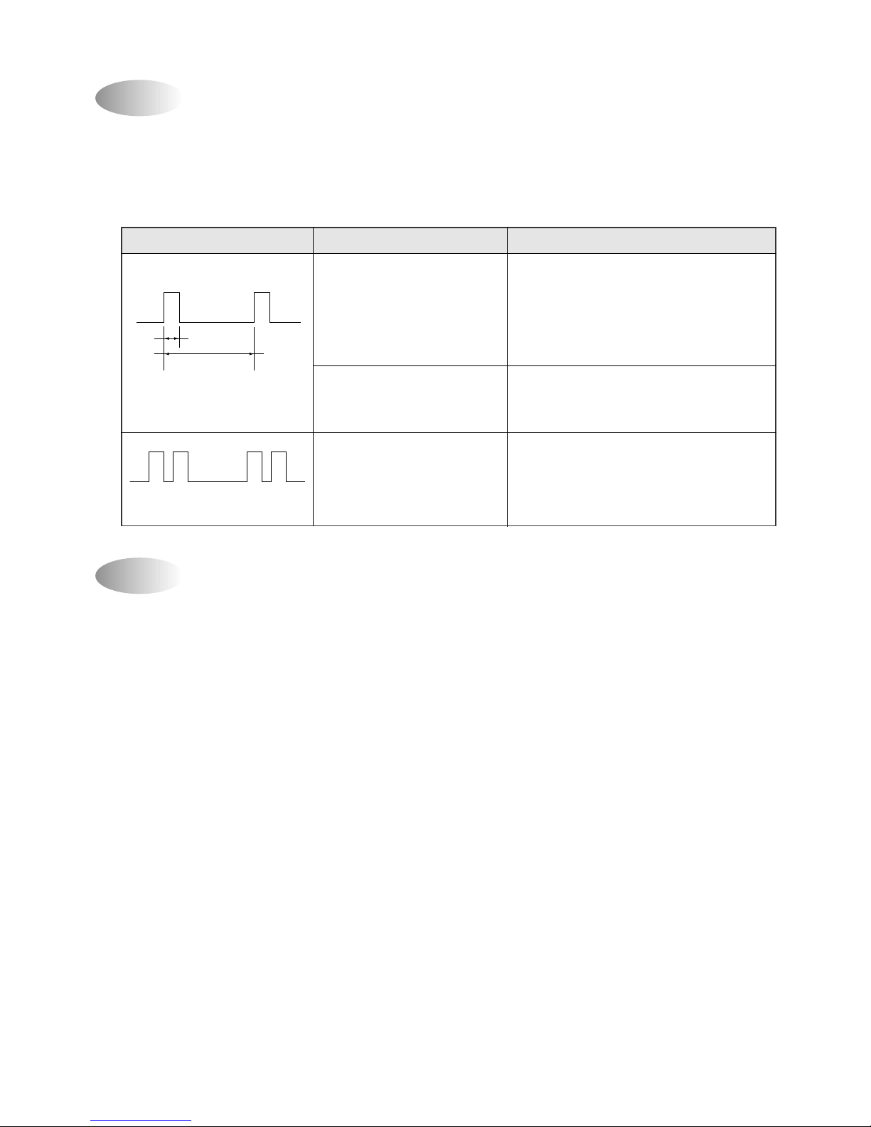
Defrost Function Chart for Outdoor Condenser
Max Load Heating Operation Diagram
• Note1 : 120sec for 24kBtu Model
• Note2 : The Temperature is over 120°C or 15 minute later.
• Note1 : 30s ON. 120s OFF when the Compressor is OFF.
• Note2 : The F an is ON when the temperature is below 49°C.
• Note3 : The Temperature is over 60°C and 1 minute later.
Comp
Start
4 Wa y
OD Fan
ID Fan
40sec
*Note1
15min
*Note2
6sec 6sec40sec
Return
60°C
Temperature (Indoor Evaporator)
57°C
49°C
38°C
ID F AN
* Note1
Monitoring
"Ultra Low"
Set V alue
"Hi, Mid, Low" "Hi" "Hi"
OD F AN OFF *Note2
OFF *Note3
COMP
22
Self-Diagnostic Function
The control will contain diagnostic test to verify the integrity of the system.
(1)Error Code Display P attern
1 ON LAMP: Blink
Self Diagnostic Function Description
1. Sensor Error
Open OR Short circuit of Sensors, Room, Indoor Coil Sensor and Outdoor Coil Sensor
Open : Micom, Input V oltage 0~0.3V, Short: Micom, Input Voltage 4.7~5.0V
2. Compressor Error
At the start operation, the Compressor is ON and 5 Minutes later, the Temperature change value of Indoor
Coil is below +/-2°C.
• Emergency Mode Operation detect only
3. 4 Wa y Valve Error
At the start operation, the Compressor is ON and then.
Indoor Coil Temperature goes up to 2°C in Cooling Operation Mode
Indoor Coil Temperature goes down to 2°C in Heation Operation Mode
LED BLINK PATTERN CASE NOTE
Room Sensor open or Short • Continuously woorking to fix room
temperature 18°C in heating mode.
• Continuously woorking to fix room
temperature 32°C in cooling mode
• I/D coil sensor open or short Do not woorking
1 times blink • O/D coil sensor open or short
• Compressor or electrical parts Continuously workiug
of compressor error.
2 times blink • Gas leak
0.5s
8s
23
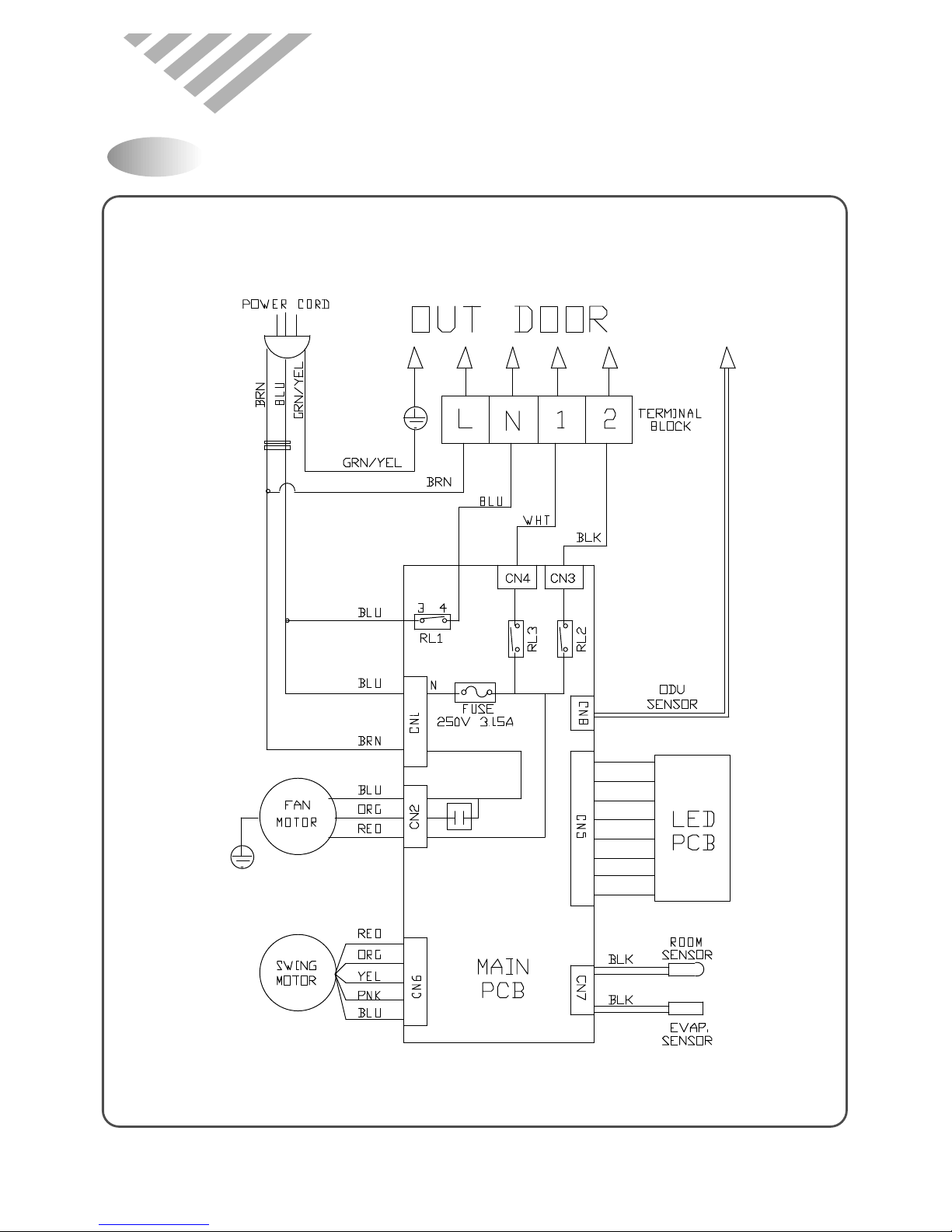
4. WIRING DIA GRAM
Indoor Unit
Circuit Diagram
DSB-093LH
 Loading...