

Page 1
OPERATION OF AIR CONDITIONER
Operation procedure-Control under the Remote controller
1
11
2
2
1
3
3
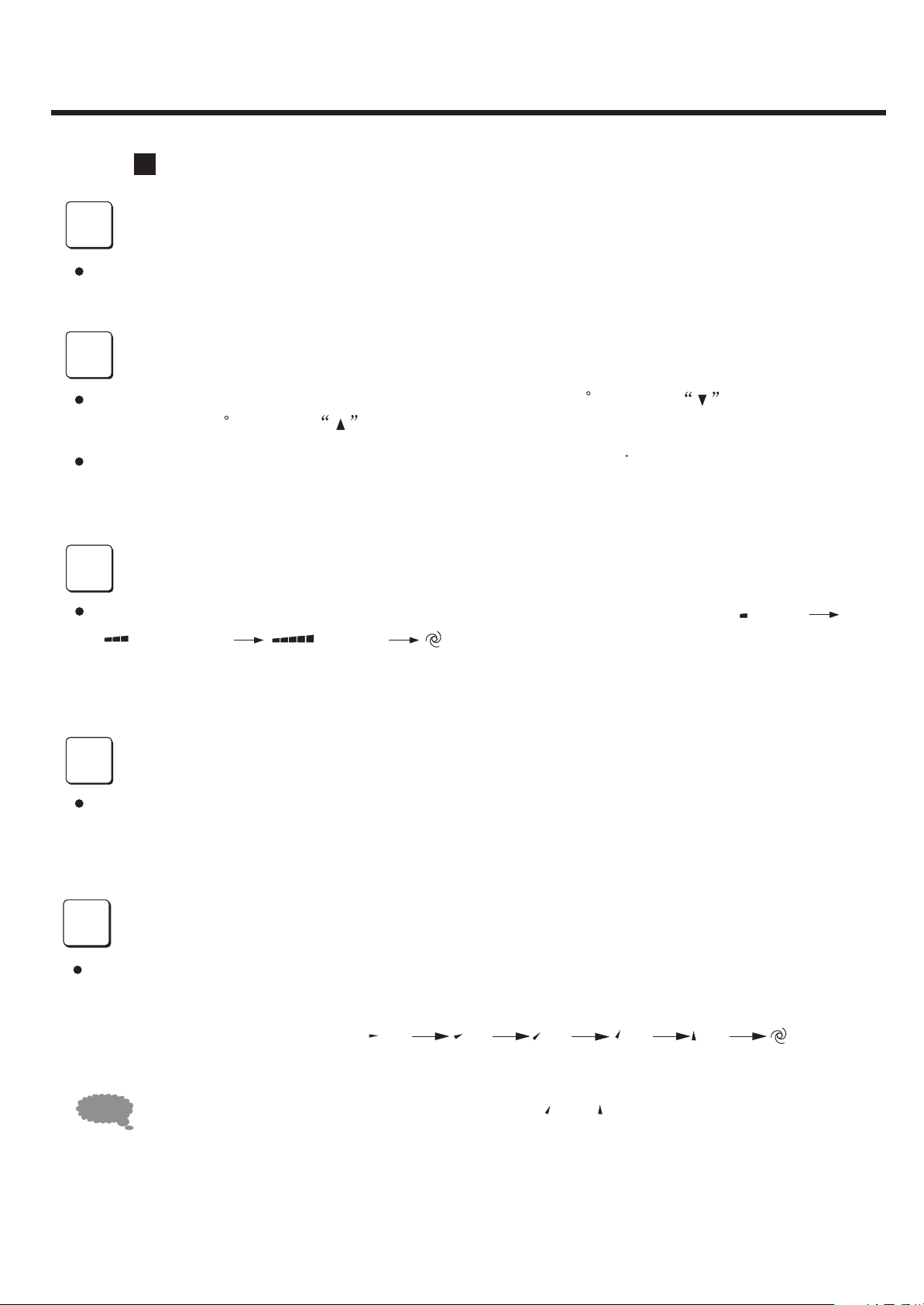
Run/Stop
Press I/O button, start operation, and stop when repressed.
Temperature adjustment
Press TEMPERATURE ADJUSTMENT button, decreases 1 by press button once,
and increase 1 C C by press button once.
Temperature change will display in the remote controller's display.
Fan speed adjustment
Press FAN SPEED button,change the fan speed of indoor unit in the order of ( low )
( medium ) ( high ) ( auto ).
4
4
5
5
1
1
NOTICE
Sleep selection
Press SLEEP button, set sleep operation, and cancel when repressed.
Air flow direction adjustment
Change up/down air flow direction
Press MANUAL SWING button, the deflector move a specific angle. Change the deflector
of indoor unit follow the order of (1) (2) (3) (4) (5) (auto).
(The deflector start to rotate automatically)(Fig.2)
In DRY or COOL mode , air blows downward in (4), (5) for one hour,
it changes to horizontal blowing automatically to prevent dropping.
1111
Page 2
OPERATION OF AIR CONDITIONER
Press AUTO SWING button, the deflector start to opreate.
2
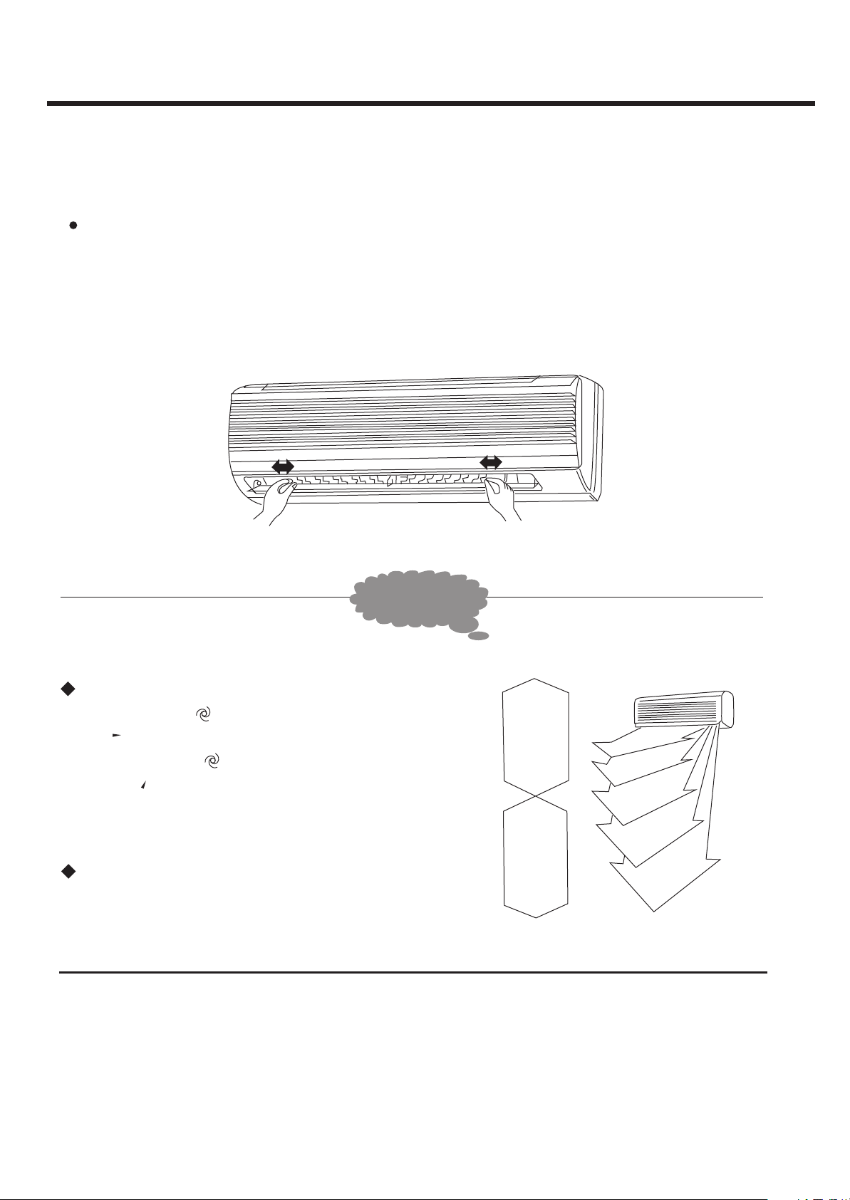
Change right/left air flow direction
Manually swing ,to change right/left air flow direction.Complete ad-
justment before operation, if adjusted during operation,the auto swinging deflector may
pinch your fingers.(Fig. 1)
Left/Right deflector
( Fig.1 )
ADVICE
In DRY or COOL mode, advise to make the
deflector with (auto), air blows downward
in (1). In HEAT mode, advise to make the
deflector with (auto), air blows downward in (4).
Control with remote controller to adjust up/down air flow direction, avoid turning deflector
with hand to avoid injury.
COOL
mode
DRY
mode
HEAT
mode
(1)
(2)
(3)
(4)
(5)
( Fig.2 )
1212
Page 3
OPERATION OF AIR CONDITIONER
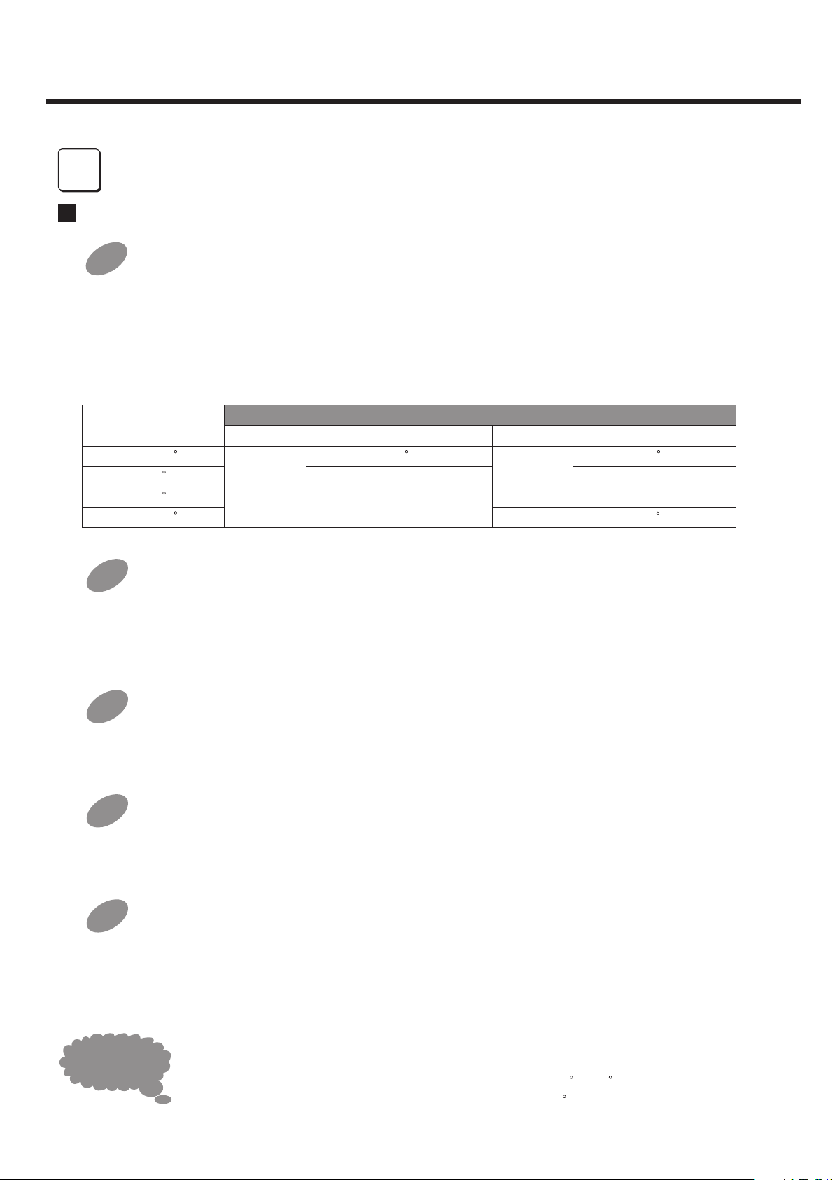
Operation mode adjustment
Cool only type has not HEAT mode .
AUTO mode
When started, operation mode will turn into COOL or DRY or HEAT mode as per room
temperature, if operation stops for two hours, it restarts in the same mode set as before
operation was stopped. Once operation mode is set,it will not be influenced even if room
temperature has changed.Press MAUNAL SWING button and SWING button to change
up/down air flow direction.
Per Room
Temperature (RT)
above 26
25-26
23-25
below 23
C
C
C
C
Cooling only type
Mode
Cool Cool
Dry RT-2
Per Setting Temperature Per Setting Temperature
C C
24
RT-2
Mode
Heat pump type
Dry
Heat
24
RT-2
RT-2
C
26
1
6
116
COOL mode
2
Press MAUNAL SWING button and SWING button to change up/down air flow direction.
Press FAN SPEED button to change the fan speed of indoor unit. Press TEMPERATURE
ADJUSTMENT button to change the setting temperature.
DRY mode
3
Press MAUNAL SWING button and SWING button to change up/down air flow direction.
Press FAN SPEED button to changes the fan speed of indoor unit.
FAN mode
4
Press MAUNAL SWING button and SWING button to change up/down air flow direction.
Press FAN SPEED button to change the fan speed of indoor unit.
HEAT mode(heat pump type)
5
Press MAUNAL SWING button and SWING button to change up/down air flow direction.
Press FAN SPEED button to change the fan speed of indoor unit. Press TEMPERATURE
ADJUSTMENT button to change the setting temperature.
1313
ADVICE
HEAT mode: Healthy warmness lies in the difference with outside temperature! The
1
setting temperature for heating shall not be too different from outside temperature.
Though it varies with area, set temperature to between 20 - 24 , Heating effect
becomes inferior when ambient temperature is below 5 .
C C
C
Page 4

OPERATION OF AIR CONDITIONER
COOL mode: How to make COOL more efficient ?
2
Close windows,put down the window curtains,and reduce sunlight to increase the cooling
effect.Attach sunlight shield film on windows to reduce sunlight entering the room.Put
outdoor unit at a place where it will be shield from direct sunlight to save energy.
DRY mode: 70% humidity is the limit for people to feel comfortable. When people
3
feel hot and suffocating, water vapor content in air is high, in other words, humidity is
high. Humidity has relation to temperature and wind. Generally speaking, the most
comfortable humidity is 60% -75% in summer and 55% - 70% in winter.
Timer operation
1
7
7
Timer operation ON
1
2
the timer will increase 1 hour, the time will display on remote controller .
3
Press button
Remote Controller display.
Press button
Controller display.
Press button or to enter time setting . press button or
Press button to enter time setting . or will be stop flicker on the
Remote Controller display.
Timer operation OFF
ON
OFF
ON
ON
SET
when air conditioner stops , of flicker on
when air conditioner operate, of flicker on
OFFONOFFONOFF
¡± ¡±
¡± ¡±
ON
one time,
the
OFF
the
Remote
If you want
or will disappear on the remote controller display.
timer operation goes off, press
button Untill set time and
CANCEL
NOTICE
If power sets off, time must be set again, otherwise Timer operation is
not right.
¡° ¡± ¡°
¡±
1414
Page 5

INSTALLATION SKETCH
DSB-077/097/127LH
above 105mm
2
above 155mm
Quantity
Indoor unit accessories
1
1
above 24mm
G
7
above 7mm
H
B
F
C
D
Indoor unit accessories
Mounting plate
Mounting plate
1 1
1 1
Tapping screw ST4 25
Tapping screw ST4 25
2
2
Expansion rubber plug
Expansion rubber plug
3 4
3 4
Expansion bolt
Expansion bolt
4
4
Battery
Battery
5
5
Remote controller
Remote controller
6
6
Felt
Felt
7
7
Adiabatic underlay
Adiabatic underlay
8
8
connecting cable
connecting cable
9
9
Drain joint
Drain joint
10
10
(supplied by customer)
(supplied by customer)
Quantity
5
5
2
2
2
2
1
1
1
1
1
1
1
1
remark
remark
6
5
above 100m
above 500mm
m
above 100mm
100mmÒÔÉÏ
above 100mm
9
A
above 350mm
Quantity
Installation accessories
Installation accessories
Connecting pipe
A
A
B
B
C
C
D
D
E
E
F
E
F
G
G
H
H
J
J
K
K
Connecting pipe
Bonding tape
Bonding tape
Clamp
Clamp
Cement nail
Cement nail
Drain hose
Drain hose
Opening cap
Opening cap
Wall-hole cover
Wall-hole cover
Indoor wall-hole cover
Indoor wall-hole cover
putty
putty
I
I
Airproof oil
Airproof oil
Shockproof rubber cushion
Shockproof rubber cushion
(supplied by customer)
(supplied by customer)
Quantity
1
1
2
2
3
3
5
5
1
1
1
1
1
1
1
1
1
1
1
1
4
4
1515
Page 6

INSTALLATION SKETCH
DSB-187LH
1
2
G
7
H
7ºÁÃ×ÒÔÉÏ
B
11
6
F
C
D
Indoor unit accessories
Mounting plate
1 1
Tapping screw ST4 25
2
Expansion rubber plug
3 4
Expansion bolt
4
Battery
5
Remote controller
6
Felt
7
Adiabatic underlay
8
connecting cable
9
Drain joint
10
11
(supplied by customer)
Clamping cover of piping
Installation accessories
Quantity
5
2
2
1
1
1
1
remark
1
Quantity
5
A
B
C
D
E
F
9
A
E
G
H
J
K
Connecting pipe
Bonding tape
Clamp
Cement nail
Drain hose
Opening cap
Wall-hole cover
Indoor wall-hole cover
putty
I
Airproof oil
Shockproof rubber cushion
(supplied by customer)
1
2
3
5
1
1
1
1
1
1
4
1616
Page 7

INSTALLATION SKETCH
DSB-247LH
1
2
4
3
7ºÁÃ×ÒÔÉÏ
B
H
G
7
F
C
D
Indoor unit accessories
Mounting plate
1 1
Tapping screw ST4 25
2
Expansion rubber plug
3 4
Expansion bolt
4
Battery
5
Remote controller
6
Felt
7
Adiabatic underlay
8
connecting cable
9
Drain joint
10
(supplied by customer)
Quantity
5
2
2
1
1
1
1
remark
6
Installation accessories
5
B
C
D
E
F
G
A
9
A
E
H
J
Connecting pipe
Big cannula
Small cannula
Drain hose
Wall cannula
Putty
Airproof oil
Cement nail
Bonding tape
I
Waterproof pad
Quantity
1
1
1
1
1
1
1
3
1
1
1717
Page 8

INSTALLATION
1
11
Secure the mounting plate
The mounting plate should be attached to the structural part of wall (post etc.).
fasten string at the central hole
fasten string at the central hole
510mm
mounting plate
18 TYPE
at least 60mm
r
5mm o
10
wall
e
m sid
fro
tappping screw
ST4 25(5)
m
m
24
at least
more
r
o
m
m
5
15
wall
e
id
m s
ore
m
mounting plate
09 12 TYPE
at least 120mm
plumb
fro
510mm
ore
m
m or
5m
7
1
all
ew
sid
m
fro
mounting plate
fasten string at the central hole
plumb
at least 120mm
°²×°ËµÃ÷
at least 60mm
m
245
m s
o
fr
m o
more
r
ll
wa
ide
2
2
90~100mm
NOTICE
Drill on the wall
Insert ruler
Align ruler with straight line.
230mm
plumb
90~100mm
22 TYPE
The holes at solid arrow position must be secured to avoid the shake of mounting plate.
The holes at solid arrow position must be secured to avoid the shake of mounting plate.
When the expansion bolts are used, two holes ( 11 20 or 11 26 ) that the distance
When the expansion screws are used, two holes ( 11¡Á20 or 11¡Á26 ) that the distance
between them is 450mm should be adopted.
between them is 450mm should be adopted.
180mm
10
Center of hole( 65mm)
18
65mm
Left rear piping
12mm 12mm
12mm 12mm
12mm 12mm
right rear piping
28mm 28mm
CenterCenter
Confirm the position of holes, and drill holes on the wall.
22 type see above figure
18 TYPE 09 12 TYPE
1818
Page 9

INSTALLATION
3
3
Wiring
1
1
Open the front panel;
Remove the screw from electrical box cover, pull the
2
2
electrical box cover away from the unit and set aside.
3
3
Remove the screw from fastener, pull the fastener
away from the unit and set aside.
Connect the cable.
4
4
5
5
Replace the fastener and electrical box cover.
Electrical box cover
Screw
Indoor unit
terminal
Fastener
Pull the connecting cable's
wire in completely
Connecting cable
09 12 TYPE 18 TYPE
Screw
Indoor unit terminal
Connecting cable
Diagram
Connecting cable
09 12 18TYPE
Electrical box cover
Screw
Indoor unit
terminal
Fastener
Pull the connecting cable's
wire in completely
1919
Pull the connecting cable's
wire in completely
Connecting cable
Fastener
Electrical box cover
Indoor unit
terminal
Screw
Indoor unit terminal
24 TYPE
Diagram
Screw
Connecting cable
Page 10

INSTALLATION(07 09 12 18 TYPE)
OUTDOOR UNIT
07 09 TYPE
N
Outdoor unit terminal
Connecting
cable
12 TYPE
Outdoor unit terminal
Connecting
cable
2
White
Blue
N
Cool only type
2
Indoor unit terminal
Connecting
cable
Yellow/Green
2
Outdoor unit terminal
N
Indoor unit terminal
Red
White
Blue
3
N
2N
Heat pump type
N
4
2
3
2
R1
4
3
4
Connecting
joint
Yellow/Green
Yellow
R2
Connecting
joint
18 TYPE
WARNING
Connecting
White
Blue
Outdoor unit terminal
Connecting
cable
White
Blue
Cool only type
The connecting cables must be clipped together.
Special cable must be used to connect indoor unit and outdoor
unit. It should be ensured that the terminals are not influenced by
external force. Poor connect may cause fire.
The electric box cover must be mounted and secured in position,
otherwise fire or electrical shock may occur because of dust or
moisture.
DSB-097LH can be connected only to a supplyed with system
impedance no more than 0.457 .
DSB-187LH no more than 0.160 In case necessary, please consult
your supply authority for system impedance information.
Yellow/Green
N
2
Cool only type
N
2
N
2
cable
Outdoor unit terminal
Connect diagram
Indoor unit terminal
Connecting
cable
Yellow/Green
Outdoor unit terminal
Yellow/Green
Red
Blue
White
Blue
Red
White
Heat pump type
3
2N
Heat pump type
N
2
2 N
3
3
4
4
4
Yellow/Green
Yellow
R1
R2
Connecting
joint
Yellow
2020
 Loading...