

Daewoo DPA-380R, DPA-380RH, DPB-500R, DPB-500RH Service Manual

CONTENTS
1. Installation Guide...........................................................................................2
2. Specification..................................................................................................6
3. Outline..........................................................................................................8
4. Operation...................................................................................................10
5. Circuit Diagram...........................................................................................20
6. Refrigerant Cycle.........................................................................................31
7. Trouble Shooting..........................................................................................32
8. Exploded Diagram ......................................................................................38
Contents
2
1. INST ALLATION GUIDE
1
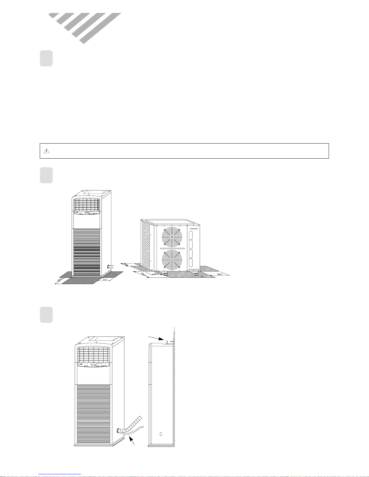
INSTALLATION PLACE
◆Indoor unit ◆Outdoor unit
Secure enough space from the neighboring
objects as shown below.
This is required to operate the unit
efficiently.
• Flat and strong place in the room
• No obstacles in front of air in/out grille
• Easy place to connect drain hose to outside of room
• Easy place to connect copper tube with outdoor unit
• Secure enough distance from neighboring objects as
shown below.
• Secure enough distance from neighboring objects as
shown below.
• A place no reach of direct ray of sun (if necessary, shield the
light)
• No obstacles in front of air in/out grille
• A place having a drain out-let
• Easy place to connect copper tube with indoor unit
• Secure enough distance from neighboring objects as shown
below.
(Indoor unit) (Outdoor unit)
CAUTION : Do not hang the outdoor unit on the wall of building, in case of falling, it may cause a serious trouble and damage.
2
SPACE TO INSTALL
3
INSTALLATION OF INDOOR UNIT
1) Drain hose should maintain downward
slope to outside of room.
2) Indoor unit should be fixed firmly with the
bracket to avoid falling down. The bracket
has several holes to fix the unit any
direction needed (fore/back/right/left)
2
1
3
4
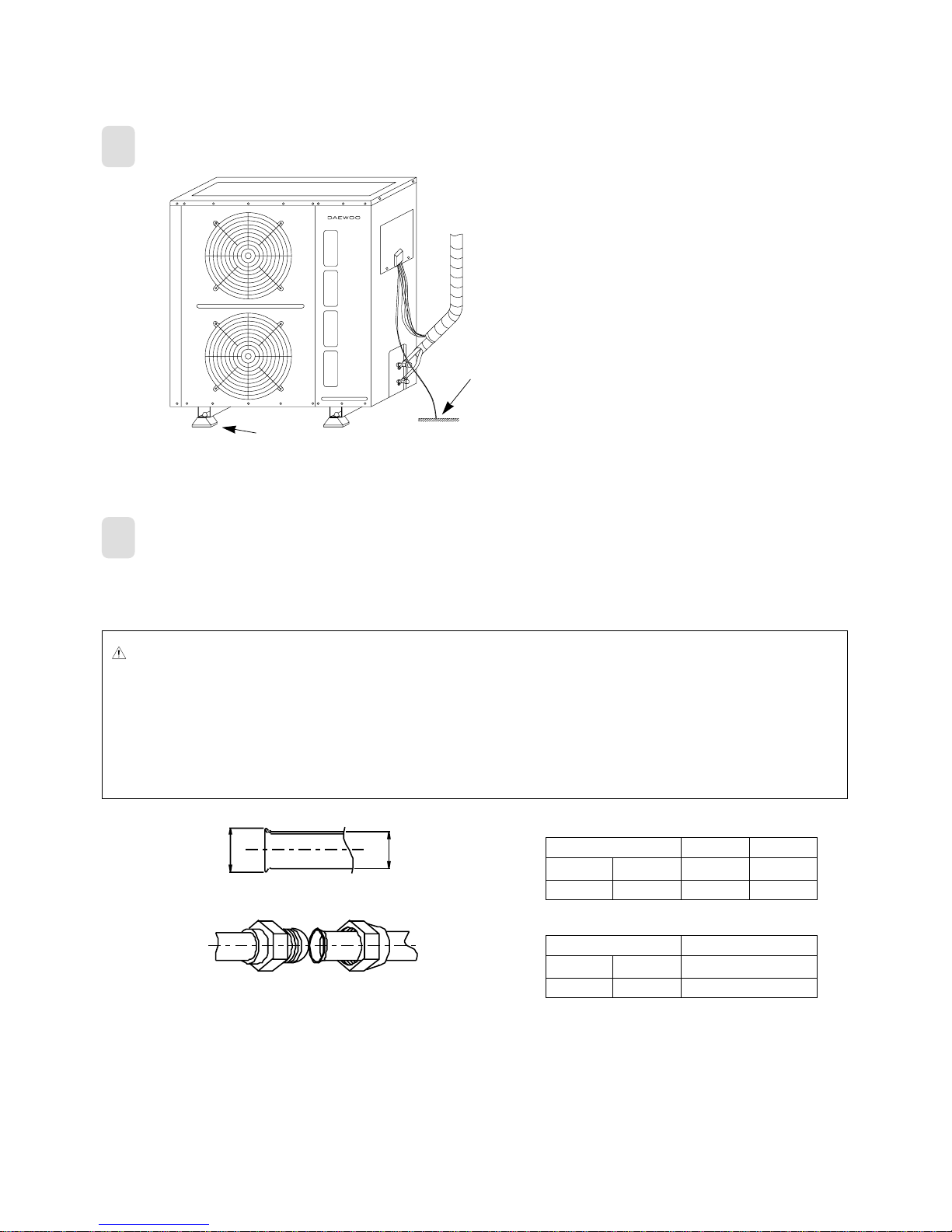
INSTALLATION OF OUTDOOR UNIT
5
REFRIGERANT TUBE CONNECTION
1) Cushion rubbers absorb vibration of
outdoor unit
2) The unit must be grounded for safety in
accordance with local electrical codes.
(Grounding resistance should be under
100 ohms
■ Specification and method of copper tube
• Connection method of copper tube is to make connection with flare nut at the end of the copper tube with a flare tool.
1
2
CAUTION
• Use designated diameter and thickness of tube.
• Connect all tube as short as possible and fix firmly.
• Less than 3M of the difference of height between indoor and outdoor unit is desirable.
• Fill up more refrigerant if the connection tube is longer than 5M (130g/M).
(The refrigerant volume filled from the factory is suitable for 5M connection)
• Be careful not to let in any dust or motes into the tube when the tube passes the wall.
• When insulating the connection, use foam rubber or equivalent.
D
A
Lquid
Gas
3/8”
5/8”
A
12.0~12.4
18.6~19.0
D
9.52
15.88
Unit: mm
Nominal diameter
Flare specification
Lquid
Gas
3/8”
5/8”
Unit: mm
Nominal diameter
Torque
300Kg • cm
500Kg • cm
Torque

4
6
ELECTRICAL WIRING
CAUTION
• Be sure to use designated wires and make it as short as possible
• Use an exclusive power supply for the air conditioner
• Use an electricity leakage interrupter having suitable capacity.
• Grounding resistance should be under 100 ohms and the grounding wire should be connected firmly to the
terminal of out door unit.
■ Wire connection of indoor and outdoor unit
• When connecting wires of indoor and outdoor unit, the numbers of terminal block and terminals of connecting wires should
match exactly as shown below.
• Terminals of connecting wires should be fixed firmly using wire fixing tool to the same direction of terminal board.

5
(MODEL: DPA-300RH)(MODEL: DPA-300R)
CONNECTING METHOD
SPECIFICATION OF WIRES
(MODEL: DPA-300R)
(MODEL: DPA-300RH)
No. of Terminal Block
Y
N
L
N1
L1
Spec
H07RN-F, 1.0mm
2
H07RN-F, 1.0mm
2
H07RN-F, 1.0mm
2
H07RN-F, 1.0mm
2
H07RN-F, 6.0mm
2
H07RN-F, 6.0mm
2
H07RN-F, 6.0mm
2
Name of Cord
CONNECTION CORD
CONNECTION CORD
CONNECTION CORD
CONNECTION CORD
POWER CORD
POWER CORD
POWER CORD
No. of Terminal Block
3
2
Y
N
L
N1
L1
Spec
H07RN-F, 1.0mm
2
H07RN-F, 1.0mm
2
H07RN-F, 1.0mm
2
H07RN-F, 1.0mm
2
H07RN-F, 1.0mm
2
H07RN-F, 1.0mm
2
H07RN-F, 6.0mm
2
H07RN-F, 6.0mm
2
H07RN-F, 6.0mm
2
Name of Cord
SIGNAL LINE
SIGNAL LINE
CONNECTION CORD
CONNECTION CORD
CONNECTION CORD
CONNECTION CORD
POWER CORD
POWER CORD
POWER CORD
6
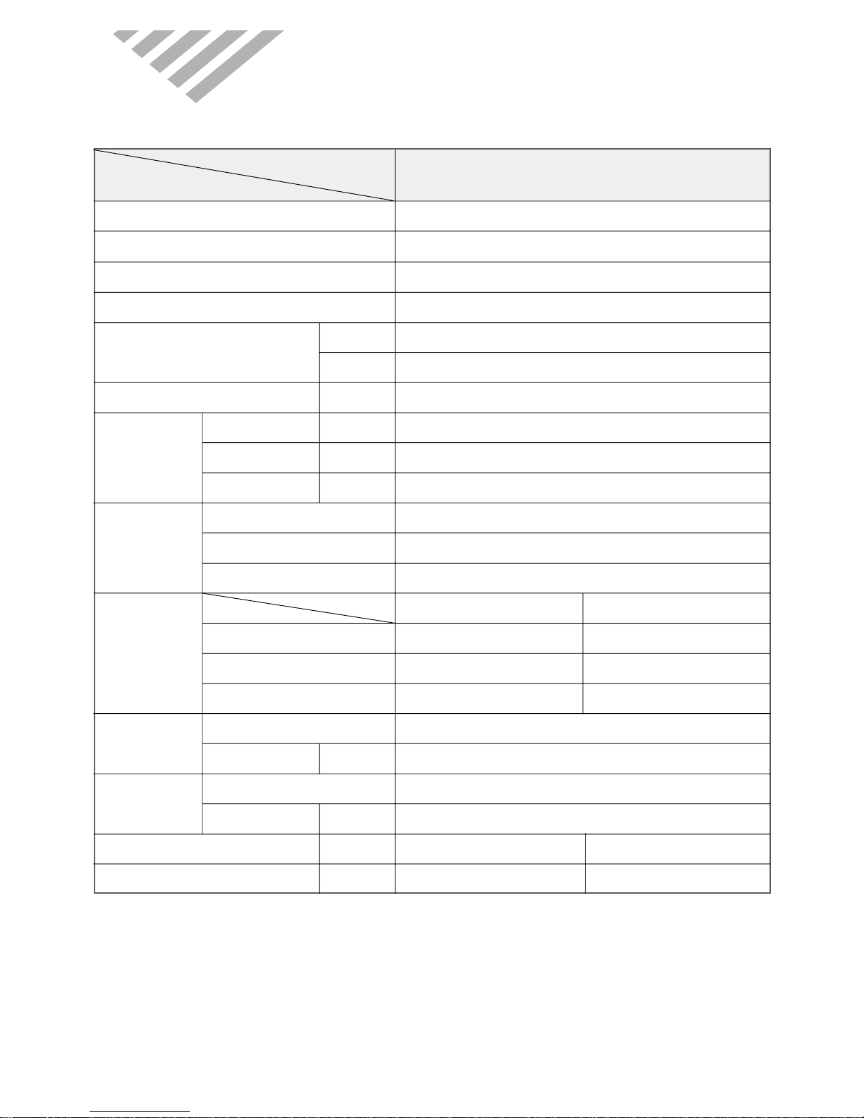
2. SPECIFIC A TIONS
MODEL
DPA-300R
ITEM
Function COOLING
Class T
Power AC 220V, 60Hz
Conditions By JIS C9812
Capacity W 11,134
Btu/h 38,000
Dehumidification l/h –
Running Current A 17.0
Power Input W 3,600
Starting Current A –
Type Recipro
Model CR38K6-PFV
Capacitor 40µF / 450 VAC
Indoor Unit Outdoor Unit
Type Sirocco Propeller fan
Capacitor 6µF/400V AC 4µF/400V AC
Motor Model Number IC-13840DWKF6B OBM-3012BI
Control Capillary
Charge Q'ty g 2,600
Type Flare
OD
(Liquid/Suction)
in(mm) 3/8” (9.52mm) / 5/8” (15.88mm)
Dimensions (W x H x D) mm 650x1,830x430 1,000x1,065x370
Net Weight kg 75 93
Electrical
Data
Compressor
Fan
Refrigerant
(R-22)
Connection
◆DPA-300R
7
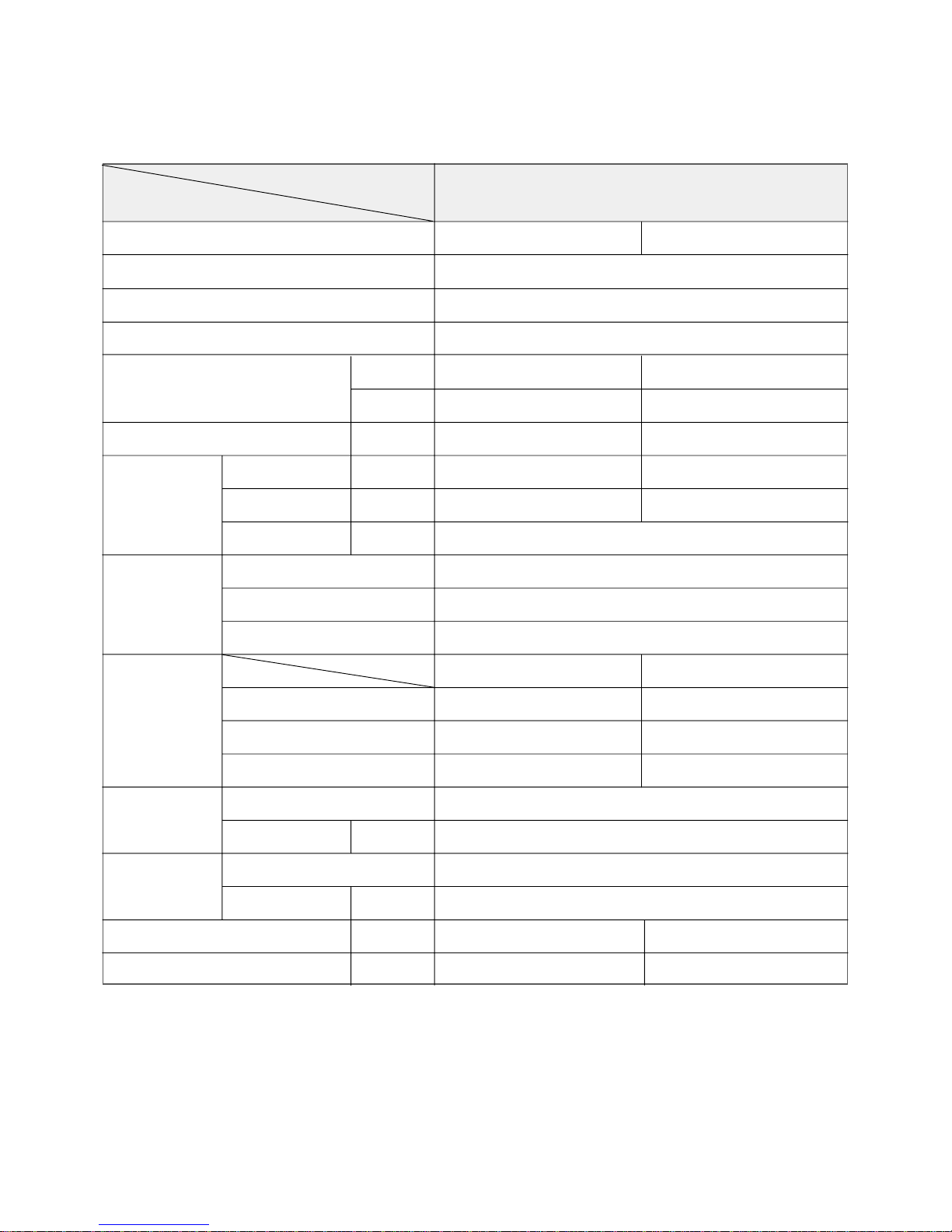
MODEL
DPA-300RH
ITEM
Function COOLING HEATING
Class T
Power AC 220V, 60Hz
Conditions By JIS C9812
Capacity W 11,134 11,134
Btu/h 38,000 38,000
Dehumidification l/h ––
Running Current A 19.0 18.0
Power Input W 4,000 3,800
Starting Current A –
Type Recipro
Model CR41KQ-PFV
Capacitor 50µF / 400 VAC
Indoor Unit Outdoor Unit
Type Sirocco Propeller fan
Capacitor 6µF/400V AC 4µF/400V AC
Motor Model Number IC-13840DWKF6B OBM-3012BI
Control Capillary
Charge Q'ty g 2,600
Type Flare
OD
(Liquid/Suction)
in(mm) 3/8” (9.52mm) / 5/8 (15.88mm)
Dimensions (W x H x D) mm 650x1,830x430 1,000x1,065x370
Net Weight kg 75 94
Electrical
Data
Compressor
Fan
Refrigerant
(R-22)
Connection
◆DPA-300RH
8
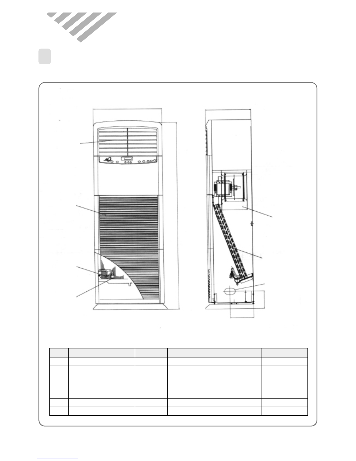
3. OUTLINE
1
INDOOR UNIT
◆DP A-300R/RH
No Part Name Quantity Description Remarks
1 Connecting Hole 3 ø60X100 (Left, Right, Back)
2 Evaporator 1 Heat Exchanger
3 Suction Grille 1 Air Inlet
4 Discharge Grille 1 Air outlet
5 Fan Blower 1 Sirocco Type
6 Joint (Gas) 1 OD ø15.88mm
7 Joint (Liquid) 1 OD ø9.52mm
4
3
5
2
1
7
6
650
1830
22
430
225
9
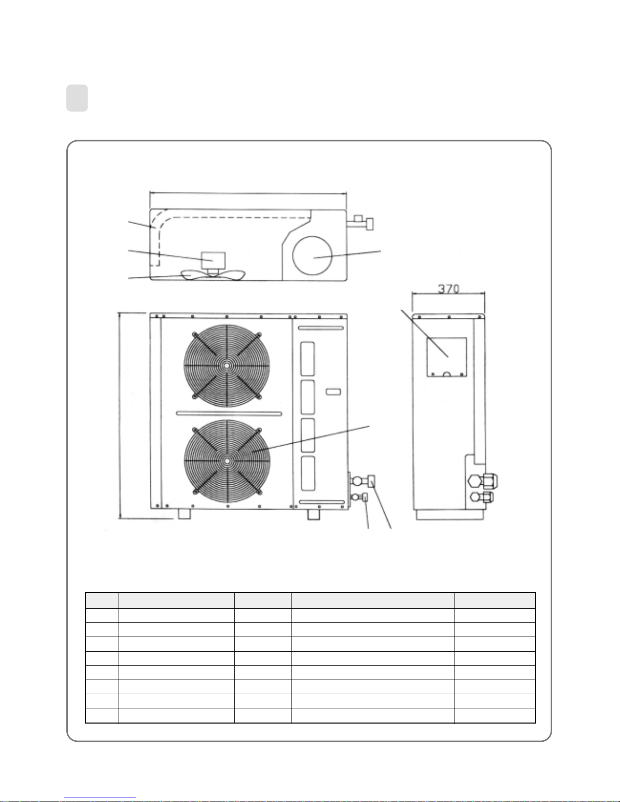
2
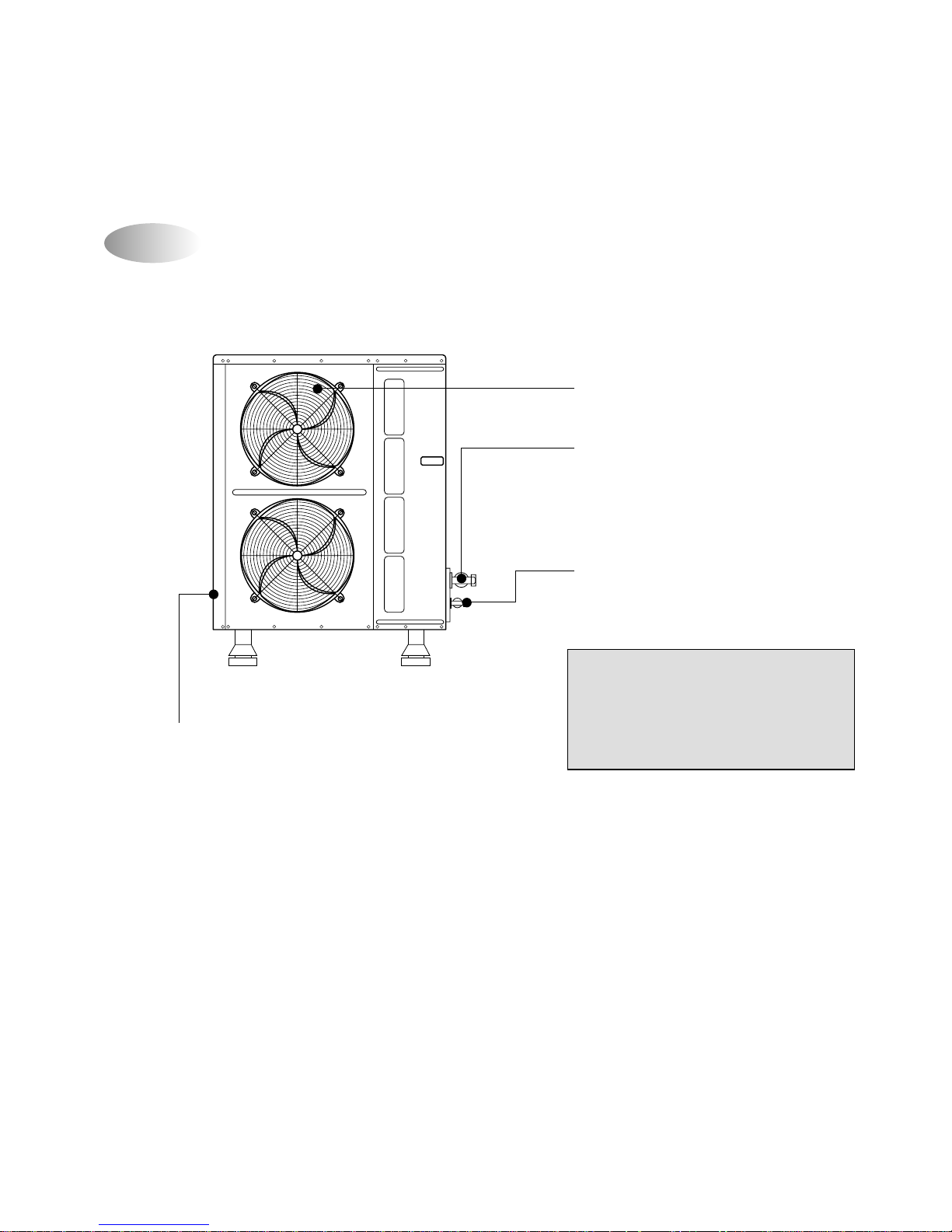
OUTDOOR UNIT
◆DP A-300R/RH
No Part Name Quantity Description Remarks
1 Service Valve (Liquid) 1 OD ø9.52mm Flare Type
2 Service Valve (Gas) 1 OD ø15.88mm Flare Type
3 Service Door 1
4 Fan Guard 1 Fan Protector
5 Fan Blower 1 Propeller type
6 Condenser 1 Heat Exchanger
7 Fan motor 1 Foor propeller fan
8 Compressor 1 Depend on Models
1000
4
1 2
6
7
5
1065
8
3
10
1
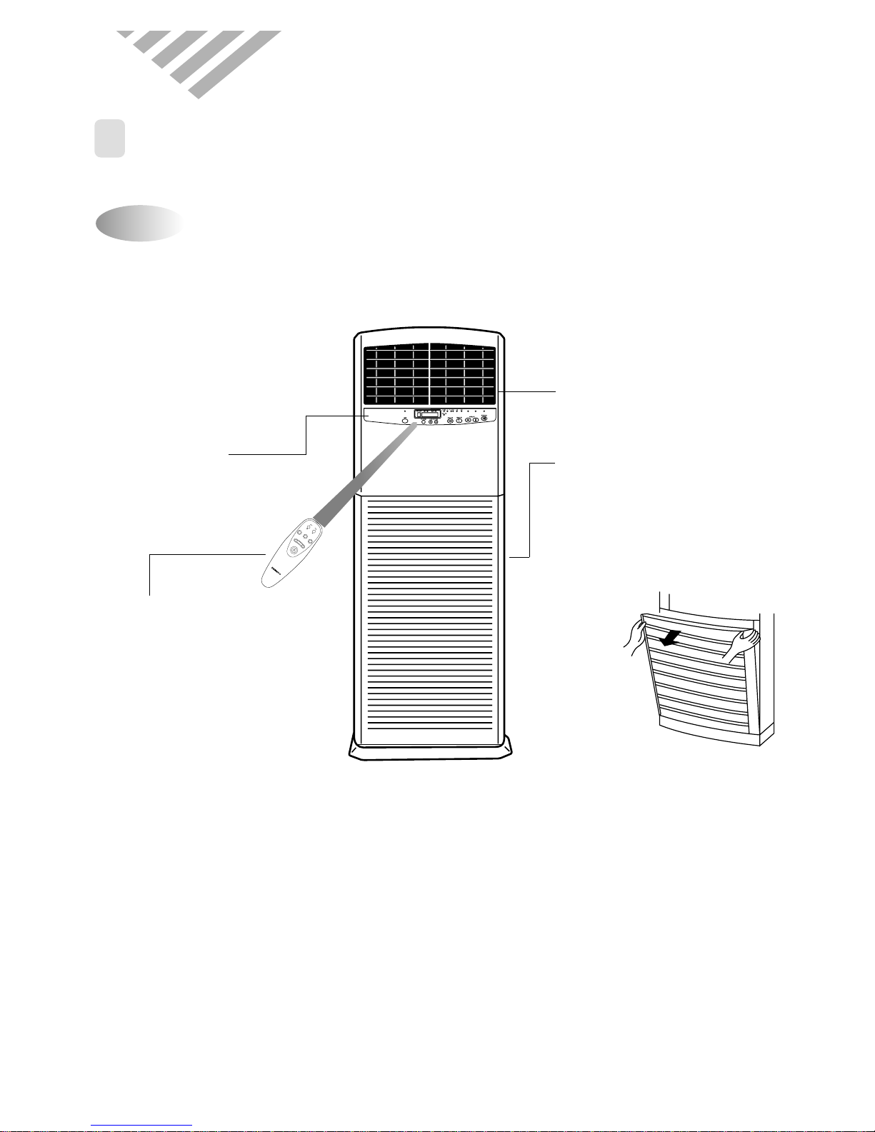
PARTS OF NAME AND FUNCTION
Indoor Unit
4. OPERA TION
MAIN CONTROLS/
REMOTE SENSOR
REMOTE CONTROLLER
- Operative distance is within 7m
from the indoor unit.
- Use toward to the remote sensor
AIR OUT
AIR IN
- There is an air filter inside this
grille.
* The method to open the air
suction grille
Pull the upper side of grille with
both hands.
FA
N
D
IR
.
L
O
C
K
M
O
D
E
F
A
N
S
P
E
E
D
T
E
M
P
F
A
N
D
IR
.
A
U
T
O
S
W
I
N
G
11
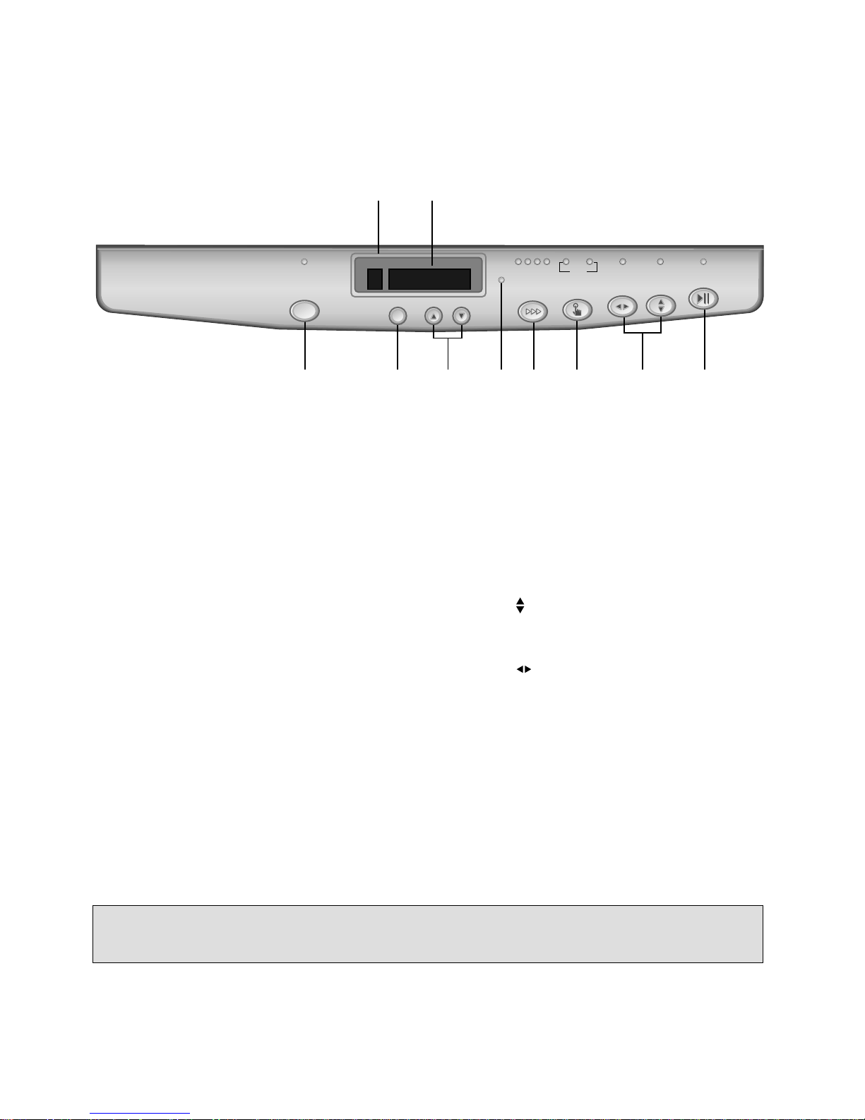
SAVE Mode Button and Indicator
TIMER ON/OFF Button
Press to set the unit off or on time.
(1, 2, 3......24hr)
TEMPERATURE & RESERVATION TIME
Button
Press to raise or lower the desired
temperature and time.
OUTDOOR UNIT OPERATION Indicator
Lights to indicate the outdoor unit operation.
FAN SPEED Button and Indicator
Press to select the fan speed
(High / Middle / Low / Auto)
MODE Button and Indicator
Press to cycle through the modes
(Cool / Fan / Heat)
FAN DIR. Button and Indicator
Press to select up/down direction for fan.
FAN DIR. Button and Indicator
Press to select left/right direction for fan.
ON/OFF Button and Indicator
Press to turn the unit on or off
Remote Sensor
TEMPERATURE & RESERVATION TIME
Indicator
1
2
3
4
5
6
7
8
9
10
1 2
9 0
3 4 5 6 7
8
REMOCON
SAVE
TIMER UP DOWN
FAN SPEED MODE
FAN DIR.
ON/OFF
CURRENT TEMP DESIRED TEMP
COMP
COOL FAN
HEAT
LO. MI. HI. AUTO
NOTE:
• Heat mode is available on the only heat pump model.
12
Outdoor Unit
CAUTION
• Do not install the outdoor unit on
unstable place like outside wall of
building or outside of balcony. In case of
falling, it may cause serious trouble and
damage.
OUTDOOR UNIT AIR IN
- If there is any obstacle in front of
the grille, the efficiency of the unit
can be lowered.
SERVICE VALVE(GAS TUBE)
SERVICE VALVE(LIQUID TUBE)
OUTDOOR UNIT AIR OUT
13
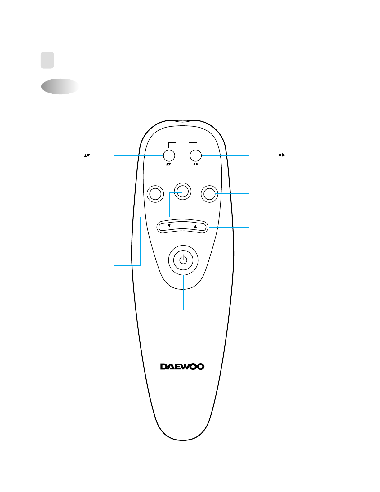
Name of Each Button
2
REMOTE CONTROLLER
FAN DIR.
LOCK MODE
FAN
SPEED
TEMP
FAN DIR.
AUTO
SWING
FAN DIR. Button
Press to select left/right
direction for fan.
TEMPERATURE Button
Press to raise or lower the
desired temperature and
time.
MODE Button
Press to cycle through
the modes
(Cool/Fan/Heat)
LOCK Button
In case that the Lock
option is applied, other
buttons on the indoor unit
don’t work.
To cancel the Lock option,
press any botton on the
remote controller.
FAN SPEED Button
Press to select the fan
speed
(High/Middle/Low/Auto)
FAN DIR. Button
Press to select up/down
direction for fan.
ON/OFF Button
Press to turn the unit on
or off
14
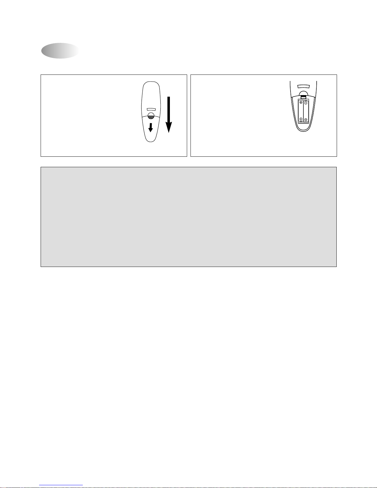
Replacing Batteries
1. Slide down further to access
the battery compartment.
2. Insert two “AAA” size
Alkaline batteries
following the polarity
diagram below.
BATTERY PRECAUTIONS
The precautions below should be followed when using batteries in this device:
1. Use only the size and type of batteries specified.
2. Be sure to follow the correct polarity when installing the batteries as indicated in the batter y compartment.
Reversed batteries maycause damage to the device.
3. Do not mix different types of batteries together (e.g. Alkaline and Carbon-zinc) or old batteries with fresh.
4. If the device is not to be used for a long period of time, remove the batteries to prevent damage or injury
from possible battery leakage.
5. Do not try to recharge batteries not intended to be recharged; they can overheat and rupture. (Follow battery
manufacturer’s directions).
 Loading...