


Training Manual
PRODUCT : COLOR - TV
DAEWOO ELECTRONICS CO., LTD.
http : //svc.dwe.co.kr
Jun . 2002

Table of contents
-
-
-
-
-
-
-
Chapter 1. TV Standards
1. Introduction----------------------------------------------------2
2. Trend of Trouble--------------------------------------------
3. How to Progress The Diagnosis of Trouble---------- 5
4. Understanding of Trouble Symptom-------------------
5. Diagnosis of Trouble---------------------------------------
6. Notes-----------------------------------------------------------
7. Color Television Circuit System------------------------- 10
Chapter 2. Trouble Shooting Charts
1. CN-001N CHASSIS-----------------------------------------11
4
5
7
9
2. CP-185 CHASSIS------------------------------------------
3. CP-385 CHASSIS------------------------------------------
4. CP-785 CHASSIS------------------------------------------
1
17
22
27

Chapter 1. TV Standards
1. Introduction
The first, color television system to be used for a public broadcast service was the
CBS(Columbia Broadcasting System) field sequential system which was adopted in
the United States in 1951.
The CBS system was subsequently replaced by the NTSC(National Television
System Committee) system which transmits all three primary signals simultaneously.
The NTSC system has been used for public broadcasting on the USA since
December 1953.
The NTSC system, which operates on a 60HZ field and 525 Scanning lines, is designed
to be compatible with the monochrome TV system in the US. The width of the video zone
is 4.5MHz and the width of the channels is 6MHz.
This system has been adopted in the USA, KOREA,CANADA,JAPAN and other countries,
and particularly where the utility electricity mains supply frequency is 60Hz.
The PAL system was proposed by W.Bruch of Germany, PAL is stand for "Phase
Alternation by Line". This system was adopted by many European Countries and
public broadcasting began in 1967 in Germany. This system is almost the same as
the NTSC system for the color TV signals, but differs in the fact that the signal are
inversed by 180 at every horizontal scanning line, therefore using a 1H delay line in the
color receiver, suing a 625 line, 50 field.
The SECAM system broadcast service began in FRANCE in 1967 which was officially
adopted by France, USSR and other countries.
The SECAM is stand for "Sequential couleurs A Memoire" This system operates on a 625
lines, 50 fields, was based on the two distinguishing features of the system,
the use of segmental color signals a memory device, the memory device took the from
of a 1H delay line in the receiver.
This system has disadvantages in the parts of phase divergence and cross talk(leakage
of signals) because of the way that the color signals,divided into two,are simultaneously
transmitted.
2
FEATURE
TV SYSTEMS STANDARD
FORMAT
NTSC PAL SECAM
SCAN LINES (H)
H-FREQ (KHZ)
V-FREQ (HZ)
PICTURE PER SEC
INTERLACED SCANING
ASPECT RATIO
VIDEO MODULATION
SOUND MODULATION (KHZ)
VIDEO BAND (MHZ)
SOUND CARRIER (MHZ)
525 625 625
15.734 15.625 15.625
59.94 50 50
29.97 25 25
2 : 1 2 : 1 2 : 1
4 : 3 4 : 3 4 : 3
AM - AM - AM +
FM±25 FM±50 AM 60%
4.2 5 6
4.5 5.5 6.5
CHANNEL BAND (MHZ)
COLOR CARRIER (MHZ)
COUNTRY
STANDARD SPEC
67 8
3.579545 4.433618 R=4.40625,B=4.25
USA, GERMANY, FRANCE,
JAPAN, W-EUROPE E-EUROPE,
KOREA CHINA, CIS
FCC CCIR CCIR
3
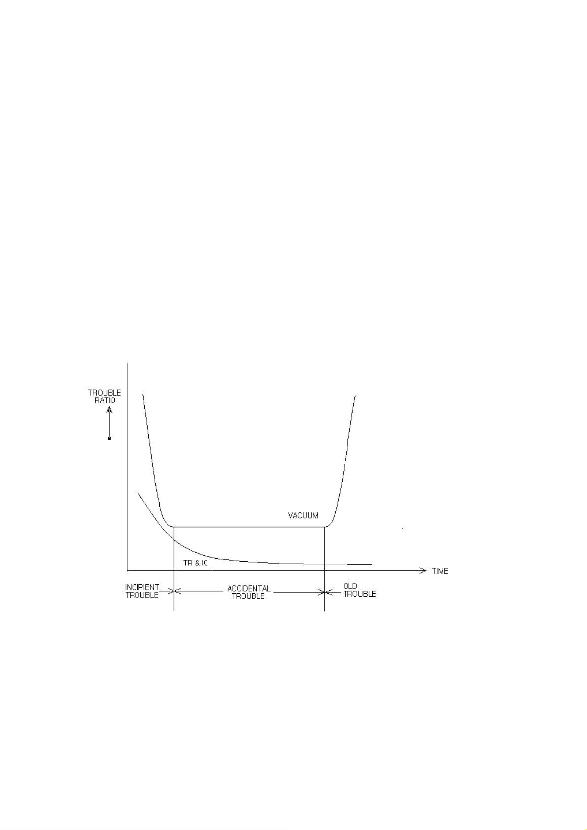
2. TREND OF TROUBLE
TV receiver is composed of a great many components and the number of which
can be different in accordance with each model. But even that only one of its
composed components is trouble, the TV receiver doesn't operate normally.
The lower the ratio of generating the trouble and the less the number of composed
components are used, the higher the reliability of the receiver is assured.
When using a receiver mode of vacuum tube the trend of trouble increases as time
goes by, but as transistor and IC make an appearance and the used components
decrease considerably be means of employing the integrated circuits,considerable
decreasing of trouble is resulted.
Recently,trouble-shooting which is required of exchanging the whole PCB as well
as the troubled components serves as the assurance of reliability and the satisfaction
of customer.
- BATH TUBE CURVE (TREND of TROUBLE) -
4

3. HOW TO PROGRESS THE DIAGNOSIS OF TROUBLE
It is not easy to repair the TV sets with prompt and accurate by clarifying
the reason of trouble out of a great many components unless the composition of
each circuit and the flow of signal should be understood systematically.
The diagnosis of trouble in TV receiver usually can be localized a major
section by observing the symptom of it. That is, an efficient order of
diagnosis, first divide the total into the two blocks and find the block in which the
trouble occurs, and again divide the block into two more in detail, by this repeat
procedures, localize to narrow section, and detect the component caused to be trouble.
The order of diagnosis is progressed as follows.
1) Observe the symptom of trouble
2) Presume the troubled circuit from the symptoms
3) Localize the trouble to a narrow section(circuit break down)
4) Find the troubled component and check
5) Replace it by a good part of the same specification.
6) Make sure the set is operated normally.
4. UNDERSTANDING OF TROUBLE SYMPTOM
It's said that the troubleshooting is started from the feeling of the strange of
picture of sound,ended to check the normal operation. Therefore understanding of
symptom is the source of shooting and short way of able to repair with efficient
and sure and also it is very important to obtain the further more information from it.
If you wish to presume the circuit of troubled, you should know the flow of signals
and each operation ,and understand the situations for the troubled circuit corresponding
to its symptom.
While as above mentioned, the diagnosis of trouble in TV receiver can be localized
to narrow section by observing the raster and picture and by listening to sound.
TV receivers exhibit the specific signs for some definite troubles, For instance no high
voltage with normal sound means no brightness on the screen.
5
Localizing the trouble to one stage and a specific component generally should be
required of test equipment such as the multimeter, oscilloscope, and pattern
generator etc.. Just with a simple ohm-meter, test of opened-resistor and
short-capacitor is possible once the trouble has been narrowed down a suspected
component. It's summarized the relation of the symptom of trouble and its circuit.
[ TABLE 1] RELATION OF SYMPTOM AND CIRCUIT
SYMPTOM OF TROUBLE RELATED CIRCUIT
NO RASTER AND NO SOUND POWER, H-DEFLECTION, u-COM,FBT
NO RASTER AND NORMAL SOUND HV,CRT,FBT
NO PICTURE AND NO SOUND LOW B+ LINE,TUNER,IF AMP,AGC,u-COM
NO PICTURE AND NORMAL SOUND VIDEO DETECTOR,VIDEO AMP,VIDEO SWITCHING
NO COLOR
INCORRECT COLOR COLOR DEMODULATOR,COLOR MATRIX,CRT DRIVE
SINGLE HORIZONTAL LINE V-DEFLECTION
CONVERGENCE DY AND PC MAGNET,CRT
NO HOLD SYNC. SYNC SEPARATOR,AFC,H-OSCILLATOR,AGC,APC
NO SOUND
SINGLE VERTICAL LINE H-DEFLECTION
CHROMA BPF,AGC,BURST AMP,CHROMA,OSCILLATOR
COLOR KILLER,CHROMA SWITCHING,COLOR CONTROL
SOUND BPF,SOUND DEMODULATOR AND AMP
VOLUME CONTROL,MUTE,SPEAKER
6
5. DIAGNOSIS OF TROUBLE
Generally because the TV circuits are composed of so many components it's
not easy to cover the wide range of total parts. Therefore you should presume the
location of trouble by dividing the circuit into the narrow section.
When trouble-shooting is carried out, the multimeter and oscilloscope are mainly
used and by checking the voltage and waveform of each terminal the troubled
component can be detected.
Above all it's very important to accumulate the experience of repair through trial
and error understanding the flow path of signals.
5.1 DIAGNOSIS OF PASSIVE COMPONENTS (RLC)
Opening, short of R,L and C or reduction of capacitance value can be checked
with a simple tester, and only opening test can be also achieved by connecting a
good part with parallel. Poor insulation and short test should be done with a
tester after turning the power off.
While, It is required of alternative testing, which measures the value alternativery by
changing the probe direction of tester, because low value may be read due to the influence
of short components. In this case the larger one is selected out of measured values.
In case that it is difficult to determine whether the part is poor or not due to the effect
of other parts, check it after opening the lead.
7

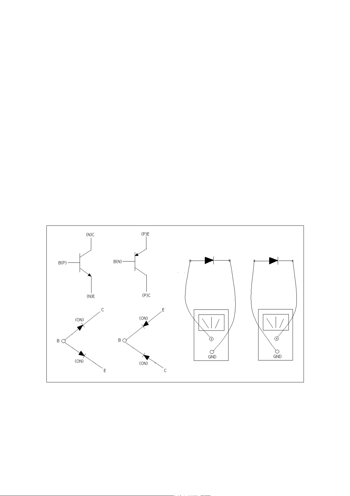
5.2 DIAGNOSIS OF TRANSISTOR CIRCUIT
In the transistor amplifier circuit, forward bias current, forward bias current flow across base and
emitter, its forward voltage is, regardless of the type of transistor, about 0.7V in silicon TR and 0.2V
in germanium TR.
After measuring VB,VE,VC AND VBE, consider it as a normal if the following conditions are satisfied
1) VBE is about 0.6V(or 0.2V), that is, forward biased.
2) VB, VE and VC are within ±20% of the value specified in circuit.
Determination of trouble is also done by checking the resistance across the base and emiter,
base and collector, emitter and collector.
That is, after measuring the forward and reverse resistance, if its difference is large it is a normal.
If its difference is small, on the contrary, if its difference is large it is a possible to check it by
the short test with a digital multimeter.
5.3 DIAGNOSIS OF IC CIRCUIT
In case the troubled circuit contains IC the reason of trouble can be IC itself or surrounding
parts. For diagnosis, first compare the voltage of each terminal with the specification, if it
appears to be the difference of ±20% it can becaused to be the reason of trouble.
While as the reason of trouble, there is a case that the supply voltage is wrong and each
terminal voltage of IC is wrong regardless of the normal supply voltage.
In this case try to exchange IC after checking the surrounding components.
As above mentioned troubleshooting is completed by only charging the poor component
for a good one, but in accordance with the circuit there can be a case which is required of
readjustment of bias or frequency etc..
In a way of preventing the recurrence of trouble, knowledge of troubled reason is important.
8

6. NOTES
Remarkable items are described in below on troubleshooting, especially special
attention should be paid to dealing with TR and IC as they are very weak to heat
such as overcurrent and static electricity.
1) Turn the power off when soldering the component.
2) Don't short the circuit during operation as TR or IC can be destroyed.
3) Solder certainly the parts dealing with large power.
4) Use the specified components when changing.
5) Return the wire originally after troubleshooting.
6) Use the soldering iron grounded at the shim of it.
7) Have on the earth ring when dealing with IC or TR.
8) Don't touch the back side of PCB with a bare hand, especially take care for
the part of high voltage.
9
 Loading...