

DAEWOO CML-710 Service Manual

LCD COLOR MONITOR
Model : CML-710
http://www.lucoms.com 2004
Service Manual
DAEWOO LUCOMS CO., LTD.
SAFETY PRECAUTIONS 2
GENERAL SAFETY INFORMATION 3
SERVICING PRECAUTIONS 4
TECHNICAL INFORMATION 8
GENERAL INFORMATION 9
PIN CONNECTOR 9
CAUTIONS FOR ADJUSTMENT AND REPAIR 9
OPERATION & ADJUSTMENT 10
ALIGNMENT PROCEDURE 16
TROUBLESHOOTING HINTS 17
BLOCK DIAGRAM 24
SCHEMATIC DIAGRAM 25
PCB PATTERN 30
INFORMATION OF PART DESCRIPTION 34
ELECTRICAL PARTS LIST 35
CONTENTS
1

2
SAFETY PRECAUTIONS
◆ Safety Check
Care should be taken while servicing the inverter that generates the high voltage to lighten CCFL of the
LCD panel.
◆ Fire & Shock Hazard
• Insert an isolation transformer between the analog color display and AC power line before servicing the
chassis.
• When servicing, pay close attention to the original lead dress especially in the high voltage circuit area;
if a short circuit is found, replace all parts which have been overheated as a result of the short circuit.
• All the protective devices must be reinstalled per original design.
• Soldering must be inspected for possible cold solder points, frayed leads, damaged insulation, solder
splashes or sharp solder points. Be certain to remove all foreign materials.
CAUTION: No modifications of any circuits should be attempted. Service work should be performed
only after you are thoroughly familiar with all of the following safety checks and servicing
guidelines.
3
GENERAL SAFETY INFORMATION
◆ Terms in the manual
CAUTION Statements identify conditions or practices that could result in damage to the equipment or
other property.
WARNING Statements identify conditions or practices that could result in personal injury or loss of
life.
◆ Terms as marked on equipment
CAUTION Statements indicate a personal injury hazard not immediately accessible as one reads the
marking or a hazard which is properly included on the equipment itself.
WARNING Statements are clearly concerning indicated personal injury hazards.
◆ Symbols in the manual
The symbols indicate where applicable cautionary or other information is to be found.
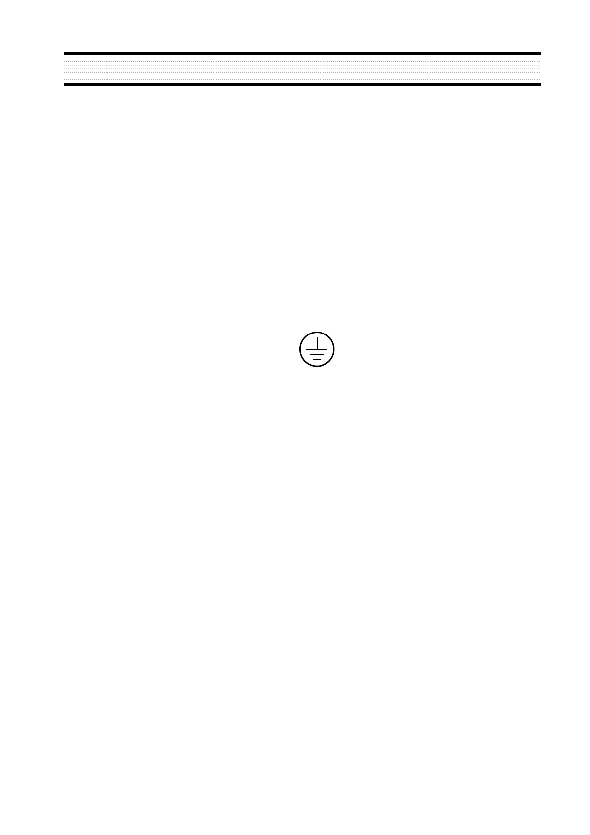
◆ Symbols as marked on equipment
Protective GROUND terminal
◆ High Voltage Warning And Critical Component Warning Label
The following warning label is on the inverter isolation case.
4
SERVICING PRECAUTIONS
◆ General Servicing Precautions
1. Always unplug the AC power cord from the AC power source before:
a. Removing or reinstalling any component, circuit board, module, or any other instrument assembly.
b. Disconnecting or reconnecting any electrical plug or other electrical connection.
c. Connecting a test substitute in parallel with an electrolytic capacitor in the instrument.
2. Test high voltage only by measuring it with an appropriate high voltage meter or other voltage
measuring device (DVM, FETVOM. etc.) equipped with a suitable high voltage probe. Do not test high
voltage by “drawing an arc”.
3. Do not any spray chemicals on or near this instrument, or any of its assemblies.
4. Unless otherwise specified in this service manual, only clean electrical contacts by applying the
following mixture to the contacts with a pipe cleaner, cotton-tipped stick, or comparable nonabrasive
applicator: 10% (by volume) Aceton and 90% (by volume) isopropyl alchohol (90%-99% strength).
5. Do not apply AC power to this instrument and/or any other of its electrical assemblies unless all the
solid-state device heat sinks are correctly installed.
6. Always connect the test instrument ground lead to the appropriate instrument chassis ground before
connecting the test instrument positive lead. Always remove the test instrument ground lead last.
7. Only use the test fixtures specified in this service manual with this instrument.
CAUTION: Before servicing instruments covered by this service manual, its supplements, and
addendum, please read and follow the SAFETY PRECAUTIONS of this manual.
NOTE: If unforeseen circumstances create conflict between the following servicing precautions and any
of the safety precautions on page 1 of this manual, always follow the safety precautions.
Remember: Safety First.
CAUTION: A wrong part substitution or incorrect polarity installation of electrolytic capacitors
may result in a explosion.
CAUTION: This is a flammable mixture. Unless specified in this service manual, lubrication of
contacts is not required.
5
SERVICING PRECAUTIONS
◆ Electrostatically Sensitive (ES) Devices
Some semiconductor (solid state) devices can be damaged easily by static electricity.
Such components are commonly called Electrostatically Sensitive (ES) Devices.
The typical examples of ES devices are integrated circuits, some field-effect transistors, and
semiconductor “chip” components. The following techniques should be used to help reduce the incidence
of component damage caused by static electricity.
1. Immediately before handling any semiconductor component or semiconductor-equipped assembly,
wipe off any electrostatic charge on your body by touching any known earth ground. Alternatively,
obtain and wear a commercially available discharging wrist strap device which should be removed for
potential shock reasons prior to applying power to the unit under testing conditions.
2. After removing the electrical assembly equipped with ES devices, place the assembly on a conductive
surface such as aluminum foil to prevent electrostatic charge buildup or exposure to the assembly.
3. Only use a grounded-tip soldering iron to solder or unsolder ES devices.
4. Only use an anti-static type solder removal device. Some solder removal devices not classified as “antistatic” can generate enough electrical charges to damage ES devices.
5.
Do not use freon-propelled chemicals. These can generate enough electrical charges to damage ES devices.
6. Do not remove a replacement ES device from its protective package until immediately before you are
ready to install it. (Most replacement ES devices are packaged with leads electrically shorted together
by conductive foam, aluminum foil, or comparable conductive material).
7. Immediately before removing the protective material from the leads of replacement ES devices, touch
the protective material to the chassis or circuit assembly into which the device will be installed.
8. Minimize bodily movements when handling unpackaged replacement ES devices. (Otherwise harmful
motion such as the brushing together clothes fabric or the lifting your foot from a carpeted floor can
generate enough static electricity to damage ES devices).
◆ General Soldering Guidelines
1. Use a grounded-tip, low-wattage soldering iron with appropriate tip size and shape that will maintain
tip temperature between a 550°F-660°F (288°C-316°C) range.
2. Use an appropriate gauge of RMA resin-core solder composed of 60 parts tin/40 parts lead.
3. Keep the soldering iron tip clean.
4. Throughly clean the surface to be soldered. Use a small wire-bristle (0.5 inch or 1.25cm) brush with a
metal handle. Do not use freon-propelled spray-on cleaners.
5. Use the following soldering technique:
a. Allow the soldering iron tip to reach normal temperature (550°F to 660°F or 288°C to 316°C)
b. Hold the soldering iron tip and solder strand against the component lead until the solder melts.
c. Quickly move the soldering iron tip to the junction of the component lead and the printed circuit foil,
and hold it there until the solder flows onto and around both the component lead and the foil.
d.
Closely inspect the solder area and remove any excess or splashed solder with a small wire-bristle brush.
CAUTION:
Be sure that no power is applied to the chassis or circuit, and observe all other safety
precautions.
CAUTION: Work quickly to avoid overheating the circuit board printed foil.
6
SERVICING PRECAUTIONS
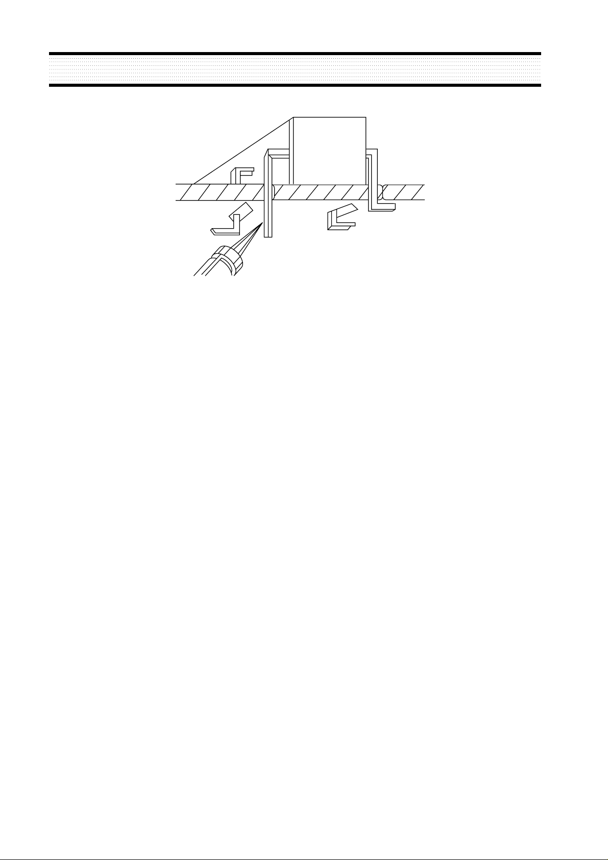
FIGURE 1. USE SOLDERING IRON TO PRY LEADS
◆ IC Removal/Replacement
Some utilized chassis circuit boards have slotted (oblong) holes through which the IC leads are inserted
and then bent flat against the circuit foil. When holes are slotted, the following technique should be used
to remove and replace the IC. When working with boards using the familiar round hole, use the standard
technique as outlined in paragraphs 5 on the page under the title of general soldering guidelines.
◆ Removal
1. Desolder and straighten each IC lead in one operation by gently prying up on the lead with the
soldering iron tip as the solder melts.
2. Draw away the melted solder with an anti-static suction-type solder removal device (or with
desoldering braid before removing the IC.
◆ Replacement
1. Carefully insert the replacement IC in the circuit board.
2. Carefully bend each IC lead against the circuit foil pad and solder it.
3. Clean the soldered areas with a small wire-bristle brush. (lt is not necessary to reapply acrylic coating
to the area).
◆ “Small-Signal” Discrete Transistor Removal/Replacement
1. Remove the defective transistor by clipping its leads as close as possible to the component body.
2. Bend the ends of each of three leads remaining on the circuit board into a “U” shape.
3. Bend the replacement transistor leads into a “U” shape.
4. Connect the replacement transistor leads to the corresponding leads extending from the circuit board
and crimp the “U” with long nose pliers to ensure metal-to-metal contact, then solder each connection.
◆ Power IC, Transistor or Devices Removal/Replacement
1. Heat and remove all solders from the device leads.
2. Remove the heatsink mounting screw (if applicable).
3. Carefully remove the device from the circuit board.
4. Insert new device in circuit board.
5. Solder each device lead and then clip off excess lead.
6. Replace heatsink.

7
◆ Diode Removal/Replacement
1. Remove defective diode by clipping its leads as close as possible to diode body.
2. Bend the two remaining leads perpendicularly to the circuit board.
3. Observing diode polarity, wrap each lead out of the new diode around the corresponding lead on the
circuit board.
4. Securely crimp each connection and solder it.
5. Inspect the solder joints of the two “original” leads on the circuit board copper side. If they are not
shiny, reheat them and apply additional solder if necessary.
SERVICING PRECAUTIONS
8
TECHNICAL INFORMATION
Panel Size 17-inch (43.2cm) diagonal
Pixel Pitch 0.264 x 0.264mm
Viewing Angle 70°(Right/Left)
60°(up), 60°(down)
Contrast Ratio 400:1 contrast ratio (typ)
Brightness 250cd/m
2
brightness (typ)
Color Filter RGB vertical stripe
Synchronization Horizontal 30 - 80KHz
Vertical 56 - 77Hz
Video Bandwidth 135MHz
Max Resolution 1280 x 1024@75Hz
Optimal Resolution 1280 x 1024@75Hz
Colors 8bit (16M Colors)
Display Area 337.9mm x 270.3mm
PC Input Signal Sync H/V separate (TTL)
Video 15 pin mini D-sub(Analog RGB)
Plug and Play VESA DDC Compatible
Power Source 100-240Vac, 50/60Hz (Free Voltage)
Power Consumption 40W
Dimension-W x H x D 386 x 398 x 190mm (with stand)
(without speaker) 386 x 346 x 60 mm (without stand)
Weight-net/gross 6.2/7.6Kg(13.6/16.7lbs)
Power Saving EPA, VESA DPMS, Nutek Compliant
Tilt Range 5° forward, 30° backward
Operating Temperature 10 ~ 40°C /50 ~ 104°F
9
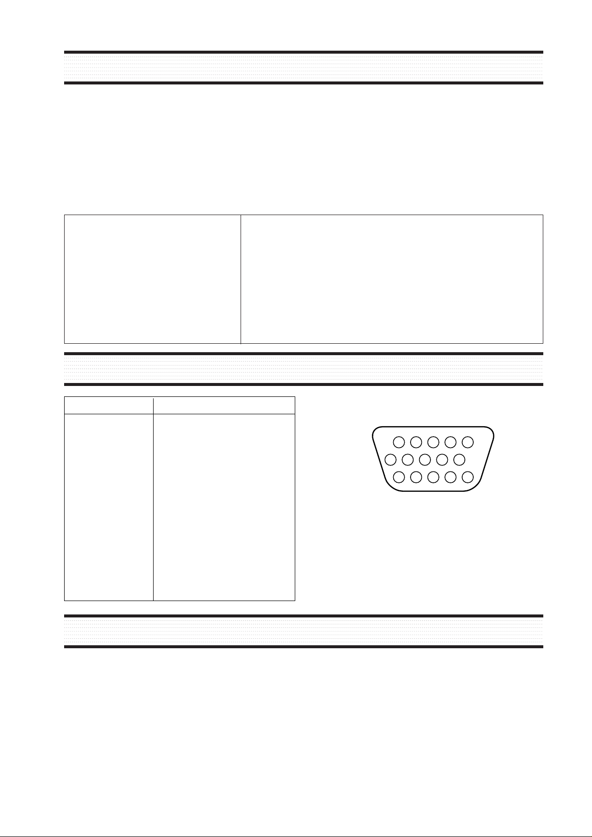
Arrangement of 15-pin D-sub connector
Pin Signal
1 Red
2 Green
3 Blue
4 GND
5 GND
6 GND - Red
7 GND - Green
8 GND - Blue
9 +5Vdc
10 GND - H.Sync
11 GND - V.Sync
12 Bi-directional Data (SDA)
13 Horizontal Sync
14 Vertical Sync (VCLK)
15 Data Clock (SCL)
1
610
15
PIN CONNECTOR
• The white balance adjustment has been done by a color analyzer in factroy. The adjustment procedure, described in
the service manual is made by a visual check.
• Allow 20 minutes warm-up time for the display before checking or adjusting only electrical specification or
function.
• Reform the leadwire after any repair work.
◆ Caution For Servicing
•
In case of servicing or replacing inverter, high voltage sometimes remains in the output of the inverter. Completely
discharge high voltage before servicing or replacing inverter to prevent a shock to the serviceman.
CAUTIONS FOR ADJUSTMENT AND REPAIR
This TFT LCD monitor automatically scans all horizontal frequencies from 30KHz to 80KHz, and all vertical frequencies
from 56Hz to 77Hz(15”- 50KHz to 75KHz). This TFT LCD monitor supports IBM PC, PC/XT, PC/AT, personal System/2
(PS/2), Apple Macintosh, and compatible users crisp text and vivid color graphics display when using the following graphics
adapters : (VGA, Super VGA, VESA, XGA, SXGA and Apple Macintosh Video Card). And so, this TFT LCD monitor has a
maximum horizontal resolution of 1280 dots and a maximum vertical resolution of 1024 lines for superior clarity of display.
By accepting analog signal inputs which level is zero to 0.7 Volts. This TFT LCD monitor can display 16.7M colors
depending on the graphics adapter and software being used.
◆ Abbreviations
ADJ Adjustment
AFC Automatic Frequency Control
TFT-LCD Thin Film Transistor Liquid Crystal Diplay
CCFL Cold Cathode Fluorescent Lamp
H.SYNC Horizontal Synchronization
OSC Oscillator
P.S.U Power Supply Unit
PWA Printed Circuit Board Wiring Assembly
R.G.B Red, Green, Blue
V.Sync Vertical Synchronization
ADC Analog Digital Converter
GENERAL INFORMATION
10
<< L710 >>
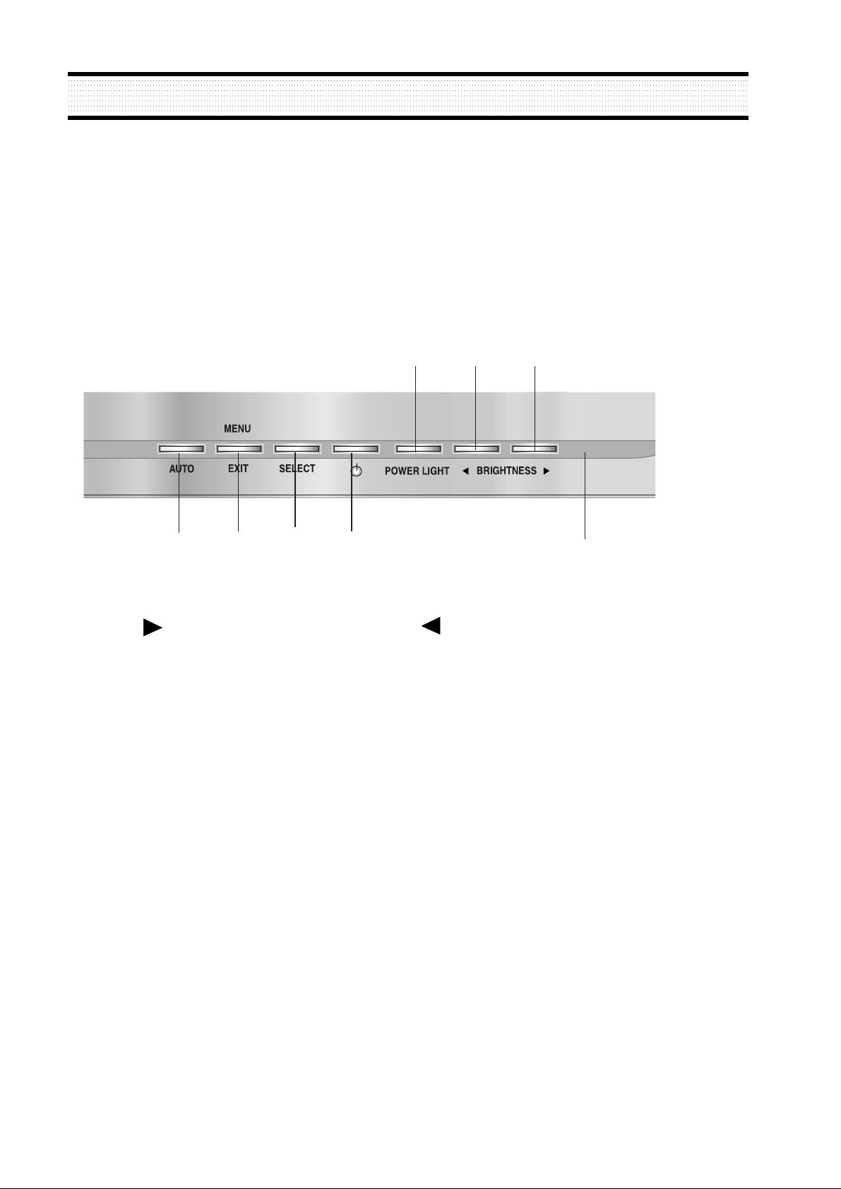
OPERATION AND ADJUSTMENT
POWER LIGHT
MENU/EXIT
Swithes the monitor on and
off.
Shows both normal operation
and power management status
with power indicator light.
POWER Indicator
POWER
1
3
4
5
7
2
Moves cursor to the right or
low window in the OSD
window and increases the
value of any selected function.
Moves cursor to the left or
high window in the OSD
window and decreases value
of any selected function.
While the OSD screen is off,
you can adjust the screen
brightness according to each
situation.
SELECT
6
Moves from top menu to sub
menu in the OSD window and
opens the function window for
the selected icon.
Turns the OSD window on.
Turns the OSD (On-Screen
Display) window off and moves
from sub menu to top menu in
the OSD window.
AUTO
8
Launches the AUTO
TRACKING function directly.
*
( )
*
( )
*
( )
*
( )
: Hot Key
3
1
2
6
7
8
45
11
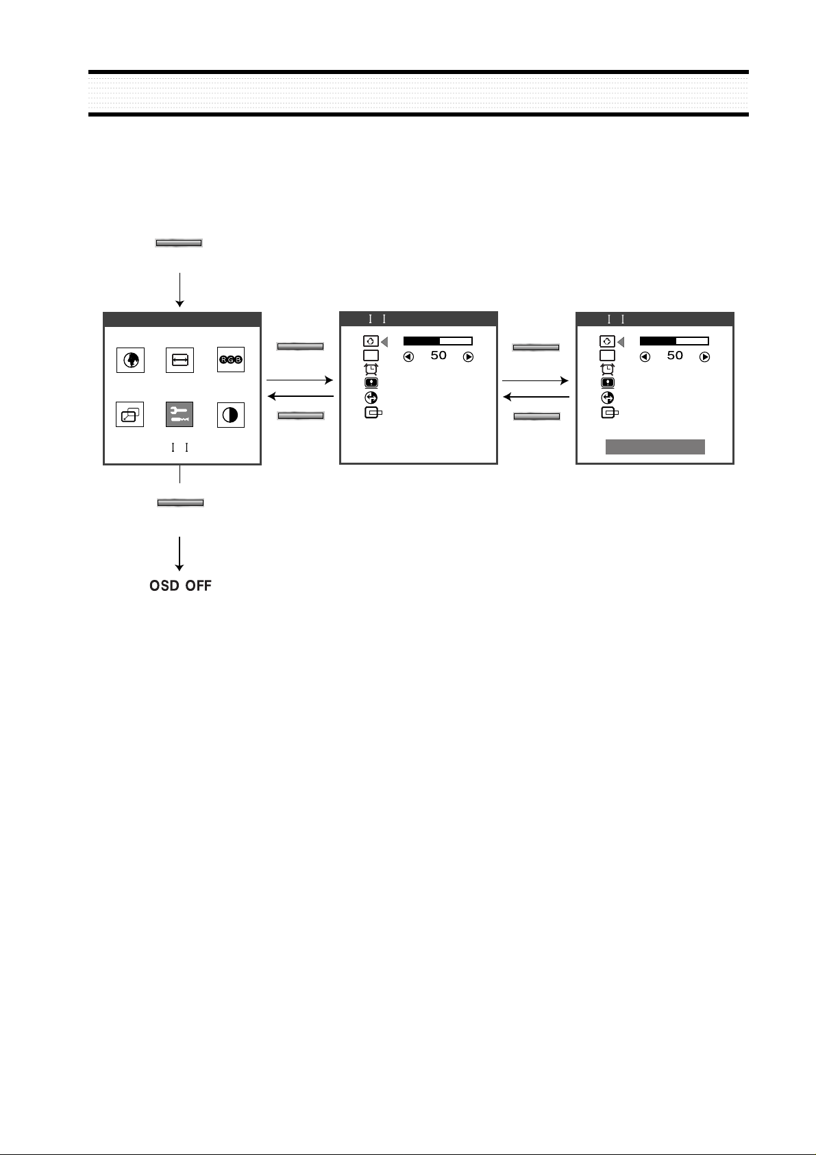
OPERATION AND ADJUSTMENT
Key Process
MENU
EXIT
EXIT
EXIT
OSD
OSD
SHARPNESS
SHARPNESS
UT L TY
UT L TY
UT L TY
1280X1024 80K 75
SELECT
SELECT
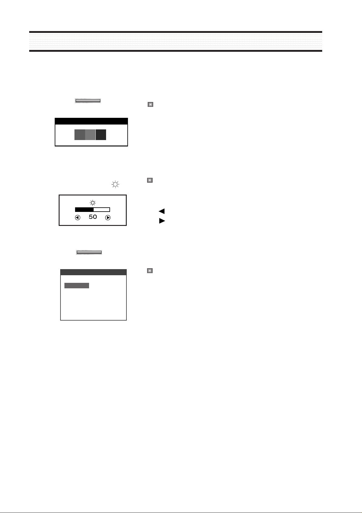
When there is no OSD, if you press this
BRIGHTNESS button, you can adjust
the brightness directly.
: decreases brightness
: increases brightness
12
When there is no OSD, if you press this
AUTO button, you can use the best
display performance fit for a current
mode.
AUTO TRACKING
AUTO
The screen will be brightened progressively
by 10%. If you carry out general PC works
such as document edition on the Movie
mode,you may shorten the life span of LCD
panel. Thus,it is recommended to verify the
selected mode before use.
POWER LIGHT
PC MODE
GAME MODE
MOVIE MODE
POWER LIGHT
HOT KEY
OPERATION AND ADJUSTMENT
BRIGHTNESS /
 Loading...