

Daewoo CM-900 Service Manual

Service Manual
Colour Television
CHASSIS: CM-900
Model: DTC-25G1VM (NO TXT)
DTC-29G1VM (NO TXT)
DTC-25G3VMR (NO TXT)
DTC-25G4VMS (NO TXT)
DTC-25G7VM (NO TXT)
DTC-29G1TM (TXT)
DTC-25G1TM (TXT)
DAEWOO ELECTRONICS CO., LTD.

SPECIFICATIONS ................................................................................................................................ 2
SAFETY INSTRUCTIONS .................................................................................................................... 3
B L OCK DIAGRAM ............................................................................................................................... 4
A L IGNMENT INS T RU C T IONS ............................................................................................................. 5
„
C M- 90 0 CHASSIS ADJU ST ME N T .................................................................................................... 5
„
SER V IC E M ODE ................................................................................................................................ 1 1
„
O T HER SERVICE FUNC T ION .......................................................................................................... 1 2
„
TEST SIGN A L S EL ECTION .............................................................................................................. 1 3
„
SER V IC E R E MOT E C ON T ROLL E R ................................................................................................. 1 4
PARTS LIST ........................................................................................................... .............................. 1 5
DIFFERENCE PARTS LIST ................................................................................................................. 2 9
PRINTED CIRCUIT BOARDS .............................................................................................................. 31
EXPLODED VIEW
„
D T C - 2 5G1VM .................................................................................................................................... 32
„
D T C - 2 9G1VM .................................................................................................................................... 33
„
D T C - 2 9G3VMR .................................................................................................................................. 34
„
D T C - 2 9G4VMS .................................................................................................................................. 3 5
„
D T C - 2 98 7 VM ..................................................................................................................................... 36
SCHEMATIC DIAGRAM ....................................................................................................................... 37
SPECIFICAT ION S
STANDARD MODEL DTC-25G1VM DTC-29G1VM
TV S TA NDA RD PAL /S EC AM-B/G, D /K, I, H , NT S C- 4.4 3 /3 .5 8
Mains Voltage AC 110 - 250V, 50/60Hz
Power Consumption 120W 145W
Sound Output Pow er 10W + 10W (AT 100% MOD , 10% THD)
Speaker 12W 8 O hm s (No rmal) X 2EA
Antenna Impedance 75 Ohm unbalanced (DIN Standard)
Tuning System Voltage Synthesize Tuning System
Number of Program 100 Channels
Reception Channel VHF - L : I1 - S8 CH (43.25 - 154.25MHz)
VHF - H : S9 - S41 CH (161.25 - 463.25M Hz)
U H F : C 1 3 - C 5 7 CH ( 4 71 .2 5 MHz - 8 6 3 .25 MHz )
Remote Control Unit R-33C
CRT 25 In ch 29 Inc h
Weight 33Kg (SET) 45Kg (SET)
Indication Program No. Display
Tuning Voltage D isplay
Vid e o In p u t D is p lay
Analog Control Display
(C o lor, B righ t, C o n t ra st, Sh a rp n e ss , T int, B /B-Ba c k/B lu e )
Volu me Con trol Dis p la y
(Bass, Treble, Balance)
Preset Display
Clock Display
NTSC state Display
ON/OFF Timer Display
Language Display

SAFETY INST RU CTIONS
NOTE
BEFORE SERVICING THIS CHASSIS, READ THE “X-RAY RADIATION PRECAUTION ”,
“SAFETY PRECAUTION” AND “P RODUCT SAFETY NOTICE” BELOW.
X-RAY RADIATION PRECAUTION
1. Excessive high voltage can produce potentially hazardous X-RAY RADIATION.To avoid such hazards,
the high voltage m ust not exceed the specified lim it.
The nominal value of the high voltage of this receiver is
26.5kv(25”), 29.5kv(29”) at max beam current.
The high voltage must not, under any circumstances,
exceed 29.0kv (25”), 31.5kv(29”).
Each tim e a receiver requires servicing, the high
voltage should be checked. It is recomm ended the
SAFETY PRECAUTION
1. Potentials of high voltage are present when this receiver
is operating. O peration of the receiver outside the cabinet or with the back cover rem oved involves a shock
hazard from the receiver.
1) Servicing should not be attempted by anyone who is
not thoroughly familiar with the prec autions neces sary
when working on highvoltage equipment.
2) Alw ays discharge the picture tube to avoid the shock
hazard before removing the anode cap.
3) Discharge the high potential of the picture tube before
handling the tube. The picture tube is highly evac
uated and if broken, glass fragments will be violently
expelled.
reading of the high voltage recorded as a part of
the service records. it is important to use an accurate and reliable high voltage meter.
2. The only source of X-RAY Radiation in this TV
receiver is the picture tube.
For continuous RADIATION protection, the
replacem ent tube must be exactly the same type
tube as specified in the parts list.
2. If a n y F u s e in th is T V r e ce iv e r is b lown, re p la c e it w ith
the FUS E specified in the Replacement Parts List.
3. When replacing a high wattage resistor(oxide metal film
resistor) in circuit board, keep the resistor 10mm aw ay
from circuit board.
4. Keep wires away from high voltage or high temperature
components.
5. This receiver must operate between A C110~250volts,
50Hz/60Hz. N E VER connect to DC supply or any other
power or frequency.
PRODUCT SAFETY NOTICE
Many electrical and m echanical parts in this
chassis have special safety-related characteristics.
These characteristics are often passed unnoticed by
a visual inspection and the X-RAY RADIATION
protection afforded by them cannot necessarily be
obtained by using replacement components rated for
higher voltage, wattage, etc.
Replacement parts which have these special safety
characteristics are identified in this manual and its
supplements, electrical components having such features are identified by designated symbol on the parts
list. Before replacing any of these com ponents, read
the parts list in this manual carefully.
The use of substitute replacem ent parts which do not
have the same safety characteristics as specified in
the parts list may created X-RAY Radiation.
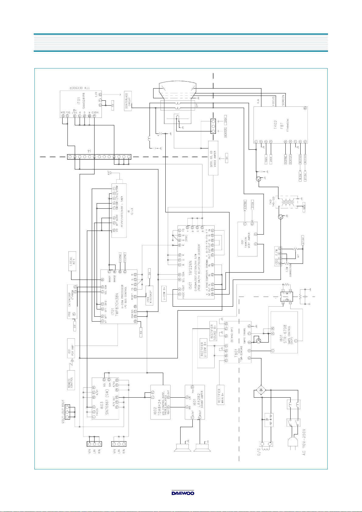
BLOC K DIAGRAM
ALIGNMENT IN STRUCTIONS
CM-900 CHASSIS ADJUSTMENT
„„„„
Application
•
This prescribes the adjustm ent procedure for the optim um electrical performance of the CM -900 chassis
co lor T V re c e ive r
General Description
•
The grade characteristics have to be marked on the test devices and measuring instruments.
Fix these equipments previously which have enough performance to acknowledge the applied standard for each test items.
•
•
Perform the adjustm ent when the chassis is in a fully stable state as long as no particular condition is specified.
•
W hen adjusting this chassis, the environmental temperature 20±2°C , relative hum idity 65± 5% and air pressure
860-1060mbar are suitable. As long as no particular condition is specified, however, it is possible to execute the
adjustment at tem perature 15-35° C , relative humidity 45-85% and air pressure 860-1060mbar.
•
The strength of the applied input signal is dropped out voltage as long as no particular condition is specified.
Power Supply
•
perform the adjustment within ± 10% of the rate voltage.
Additional Remark
In this test, the subject matter of the open/close applies in accordance with the technical standard control rule TESNO-001.
•
1. PCB ADJUSTMENT
1-1. Channel Presetting
CH MEMORY CH. SYSTEM PATTERN
01 2 PAL -B RETM A
02 4 PAL -B DEM
03 5 PAL -B C RO SS HATCH
04 8 PAL -B RED
05 10 PAL -B COLO R B AR
06 12 SECAM -B SECAM -COLOR
07 18 PAL -K RETM A
08 21 PAL -G R,B,W
09 25 PAL -G COLO R BAR
10 31 PAL -I COLO R BAR
11 38 PAL -I DEM
12 51 PAL -I RETM A
13 5 NTSC -M COLOR BAR
14 8 NTSC -M R ETMA
15 10 NTSC -M LAD Y

2. Initializing
- To use only w hen you change the EEPROM .
- Push the M U TE key of the user remocon, at the sam e tim e push the MEN U button on the Mask Front. And then it is a
service mode.
- In service mode, as push the REC ALL key of the user remocon, at the sam e tim e push the CH UP button on the M ask
Front. And then it is initialized.
- It is n o t n e ce s s a ry to p ro d u c t a t a fa cto ry
- After initializing, turn off and then turn on the power.
- R efe r ‘ S E R VIC E MO DE’.
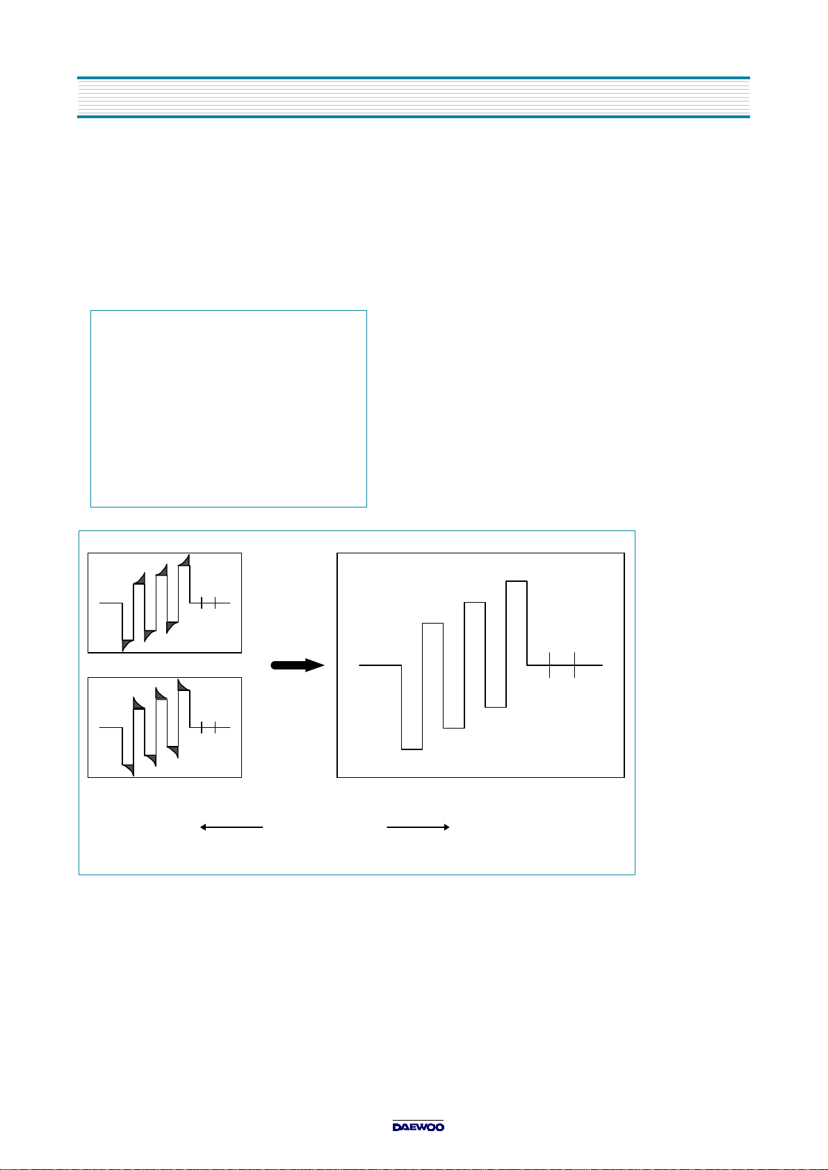
3. Screen Adjustment
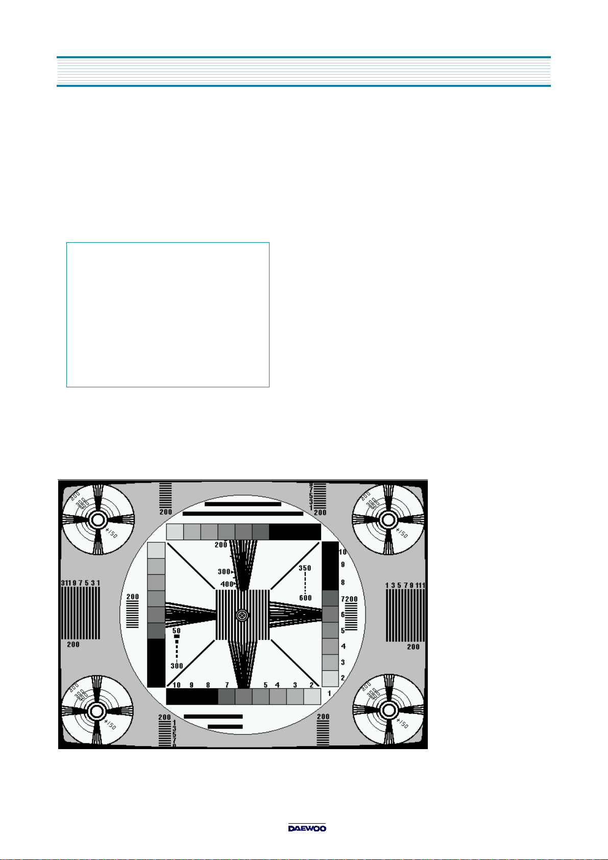
- Receive the RETM A signal.
- Push the SC R EE N O N key of the Service Rem ocon and make to be displayed the Horizontal line.
- Do not adjust the color w hat this line is displayed, but add the other color data until the H orizontal line is white.
A t th is time to u s e R ,G,B C UT O FF.
- After adjustm ent the Horizontal line is white, turn the screen VR of FBT until the Horizontal line disappear. (to the left)
- Push SCREE N O FF key of the service remocon, it will be displayed as like ‘Fig.1’.
- Push the N OR M AL key or W/B key of service rem ocon, then ‘Fig.1’ disappear.
0
127
127
127
127
127
- -
M.M
G.G
B.G
R.C
G.C
B.C
<Fig. 1>
4. White Balance Adju stment
- Receive the RETM A signal
- Set all condition to the N ormal I. (Push the NOR M AL key of the service remocon.)
- Connect the JIG for white balance adjustment.
- First, adjust high beam. Use G,B GAIN key of the service remocon. (X=288, Y=301 for W /B)
- And then adjust low beam again using R,G,B CUT O FF key.
(At this tim e, if the high beam is changed, adjust again about tw o tim es.)
- If you adjust high beam and low beam at the same tim e, it is not any problem what is used first, R,G,B CUT O FF or
G,B GAIN key.
5. Vertical / Horizontal Adjustment
- Receive the Retma signal (for PAL system)
- Set all condition to the N ormal I. (Push the NOR M AL key of the service remocon.)
5-1. V-CENTER
- Push the V.C(P/N) key of the service remocon, then it is displayed like ‘Fig 2’
- Adjust to use DATA U P /DO WN key so that the center of Retma Pattern may be located in the Vertical center of the CRT
H.P(P)
H.P(N)
V.C(P)
V.C(N)
V.H(P)
V.H(N)
V.L
<Fig. 2>
8
13
0
0
71
71
2
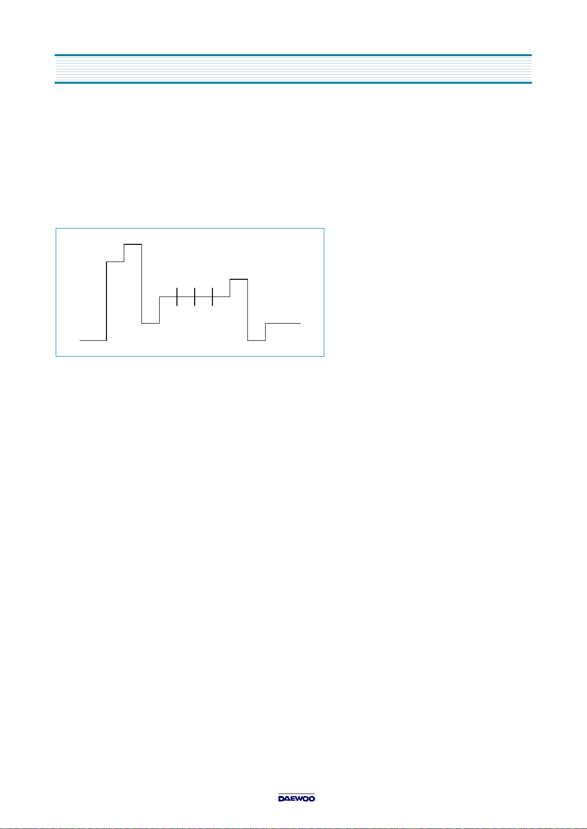
5-2. V-HEIGHT
- Push the V.H(P/N) key of the service remocon, and the cursor indicate V.H(P) (Fig 2).
- Adjust to use DATA U P /DOW N key so that the Height number “9” m ay be seen at the edge
above or below from the end of the CR T.
<Fig. 3>

5-3. V-LINEARITY
- Push the V.L key of the service remocon, and the cursor indicate V.L (Fig 2).
- A d ju st to u s e DATA UP/D O WN ke y s o th a t th e Retma P a tte rn is th e mo s t co mp lete c irc le .
5-4. H-CENTER
- Push the H .P(P) key of the service remocon, and the cursor indicate H .P(P) (Fig 2).
- Adjust to use DATA U P /DOW N key so that the Width num ber at the edge of left/ rig h t s ide ma y b e s e e n th e s a me .
6. Pincusion Adjustment
- Receive the CRO SS-HATCH signal.
- Turn E/W V R (R401) of the main PCB so that the second vertical line of the left side m ay be straightened. (like Fig.4)
(SECOND VERTICAL LINE)
<Fig. 4>
7. Width Adjustment
- Receive the Retma signal (for PAL system)
- Turn VR(R402) of the main PCB so that the Width number “11” may be seen at the edge of left and right side.
(like Fig.3)
8. Secam Bell Filter Adjustment
- Receive the SECA M C olor Bar signal
- Connect JIG to the Pin No.36 of TB1226N(I501)
- Push the SE C AM key of the service remocon, then it is displayed like ‘Fig 5’
- Move the cursor at B .F with ITEM key of the service remocon.
- A d ju st to u s e DATA UP/D O WN ke y s o th a t th e wav e fo rm m a y b e fla t like F ig .6
13
8
2
- -
- -
- -
- -
R.Y
B.Y
B.F
<Fig. 5>
AB
AB
AB
BEFORE ADJUSTMENT AFTER
<Fig. 6>
9. Secam White Balance Adjustment
- Receive the SECA M C olor Bar signal
- Connect JIG to the Pin No.35 of TB1226N(I501)
- Push the SE C AM key of the service remocon, then it is displayed like ‘Fig 5’
- Move the cursor at R -Y with ITEM key of the service remocon.
- A d ju s t ‘A’,’B’ b lo c k is fla t with ‘C ’ u s in g DATA U P/D OWN k e y lik e F ig 7 .
ABC
<Fig. 7>
- Move the JIG to the Pin No.36 of TB1226N (I501).
- M o v e th e c u rs o r a t B -Y with IT EM k e y o f the s e rv ic e re mo c o n
- A d ju s t ‘A’,’B’ b lo c k is fla t with ‘C ’ u s in g DATA U P/D OWN k e y lik e F ig 7 .
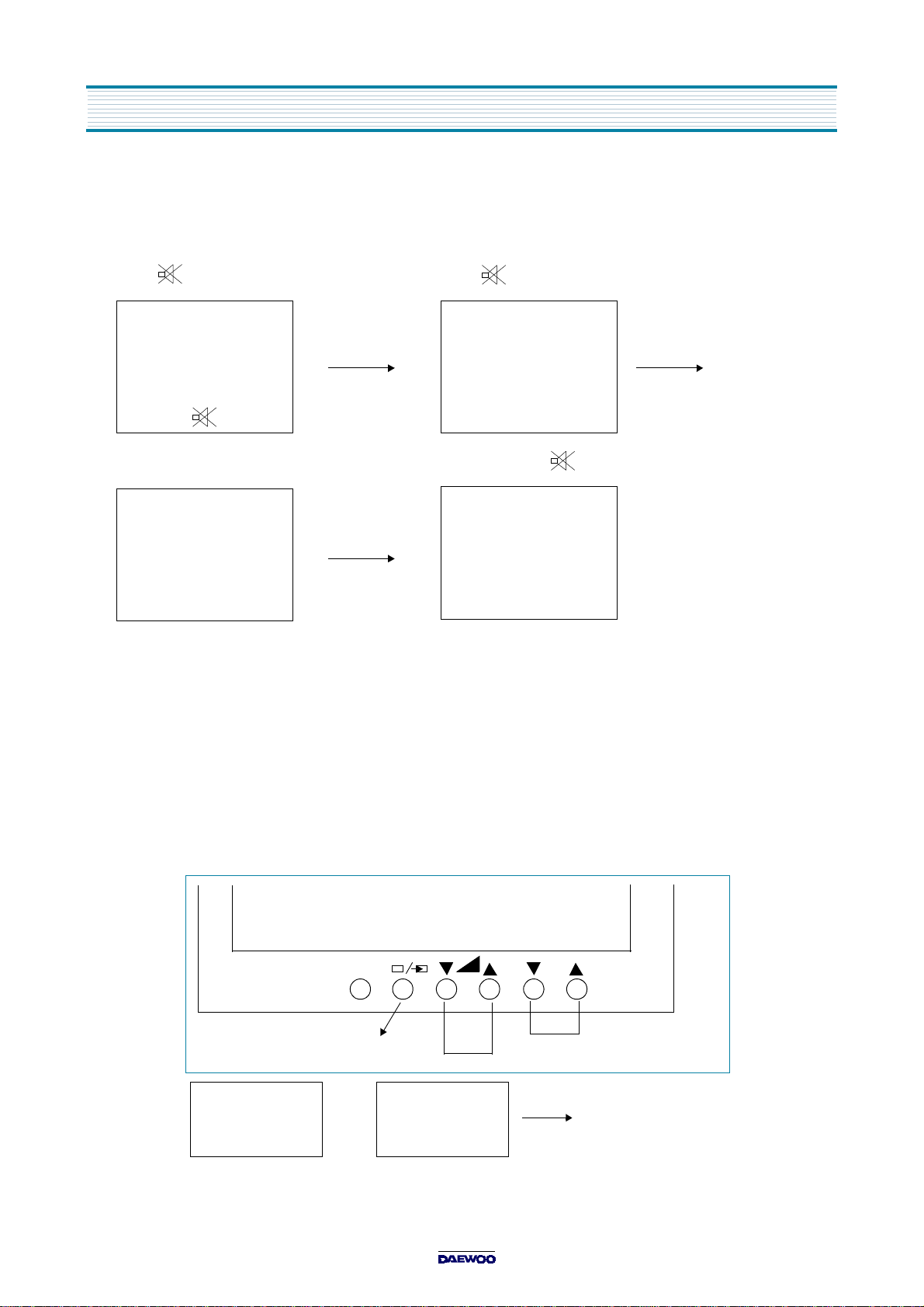
SERVICE MODE
„„„„
1. ENTERING TO SERVICE M ODE (USE USER REMOTE CONTROL)
1) Press button once on Remote control. 2) Press button again to keep pressing.
3) Press MEN U button on TV set, at the same time to keep pressing the button
127
127
127
127
127
1
13
(Se rv ice mod e d isp la y )
R.C
G.C
B.C
G.G
B.G
B.F
R-Y
2. Selection the adjusting item s
Every pressing of channel
(
button for reverse order )
button changes the adjustment item s in the following order
3. Adjusting the DATA
Pressing of volum e
(
) or () w ill c hange the value of data.
4. EXIT from service mode
Press POW ER button to turn off the TV once.
R.C
Red Cutoff
RECA LL key
(in th e R e mote
control)
(Keep pressing the
Recal Button)
MENU
PR
(in the TV Front
Panel)
(Pre s s the ‘P R
'
PR
The adjusting item
D a ta ad ju s tingHorizontal line on/off
Init ia liz a tio n o f t h e Memor y
(I701)
button)
 Loading...