

Page 1

S/M No. : TCM012MEF0
Service Manual
Color Television
CHASSIS : CM-012M
Model : DTH-29M2FS
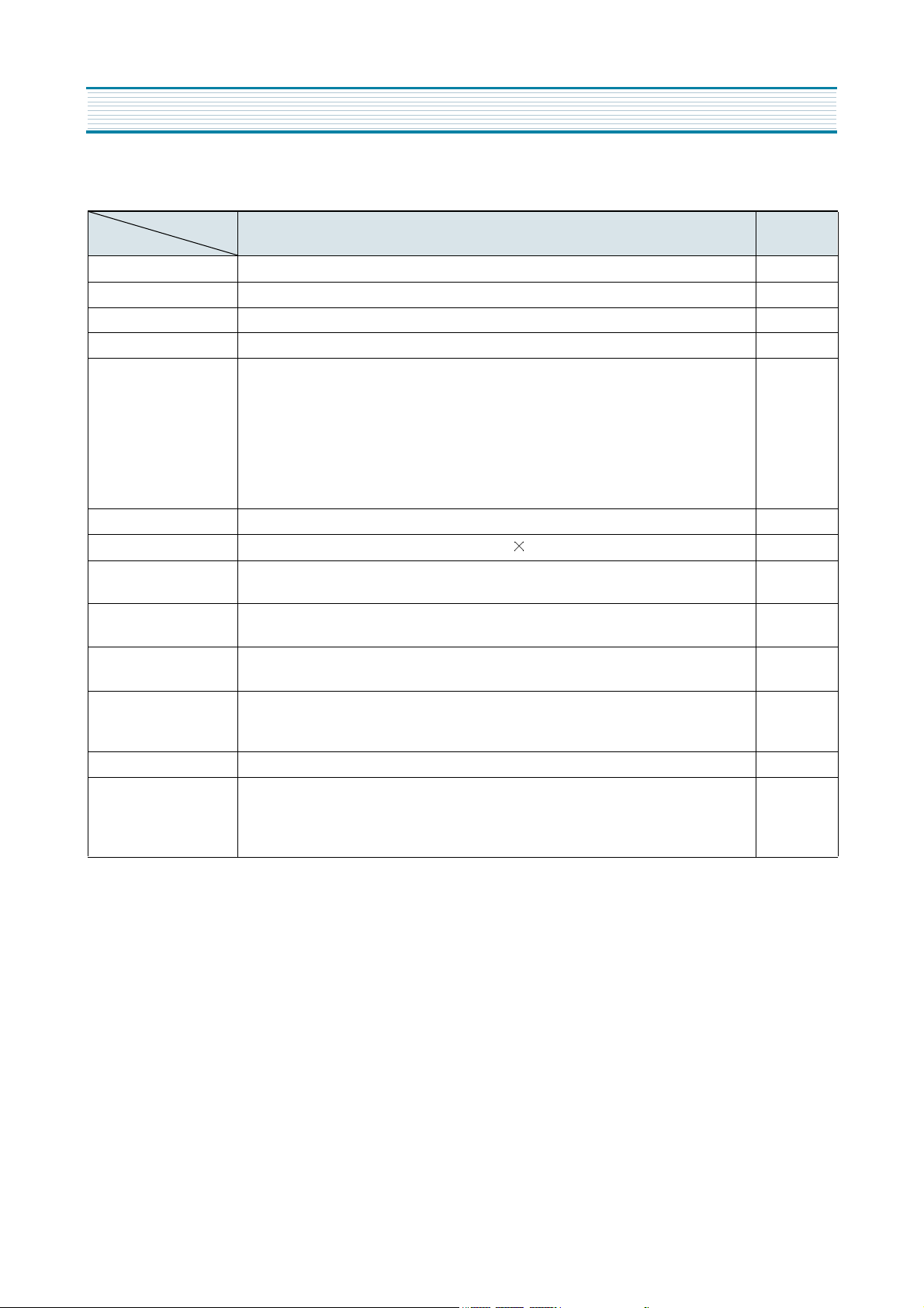
Specification
Items
TV Standard
Power Input
Power Consumption
Tuning System
Tuning Ranges
Sound Output
Speaker
Antenna Input Impedance
Auxiliary Input Terminal
Auxiliary Output Terminal
Intermediate Frequencies
Model
UHF(H): CH7-CH13
UHF : CH14-CH69
CATV VHF(L) : 5A, A,B, A-5-A-1
CH2 - CH6
VHF(H) : C-W+11
CH7 - CH13
UHF : W+12-W+84
8 ohm
Picture IF Carrier Frequency : 45.75MHz
Sound IF Carrier Frequency : 41.25MHz
Color Sub-Carrier Frequency : 3.579545MHz
DTH-29M2FS
DTH-29M2FS
PAL-M/N
220V, 50/60Hz
125W
Frequency Synthesizer(FS)Tuning System
TV VHF(L) : CH2 - CH6
7W+7W
12W 2EA
75 ohm Unbalanced
Font: Video , Audio(R,L)
Rear: Video, Audio(R,L)
Rear: Video, Audio(R,L)
Remote Control
Special Function
R-43A05
1) Icon Type
2) 4-Language OSD
3) With CAPTION
4) CH Label
5) Digital Sensor
6) Surround
7) AVC
8) Wide Picture(Option)
D AEW OO ELECTR ONICS CO., LTD
http : //svc.dwe .co.kr
Feb. 2001
Page 2

TABLE OF CONTENTS
SPECIFICATIONS...............................................................................................................................2
CIRCUIT BLOCK DIAGRAM.............................................................................................................. 3
ALIGNMENT INSTRUCTIONS............................................................................................................4
YOUR REMOTE CONTROL............................................................................................................................4
SERVICE MODE ADJUSTMENT....................................................................................................................5
ASSEMBLY ADJUSTMENT.............................................................................................................................6
SCHEMATIC DIAGRAM......................................................................................................................10
ELECTRICAL PARTS LIST.................................................................................................................11
EXPLODED VIEW...............................................................................................................................20
PRINTED CIRCUIT BOARD................................................................................................................21
APPENDIX (Appendix is provide only by internet [http://svc.dwe.co.kr])
IC DESCRIPTION................................................................................................................................1
CHIP COMPONENTS POSITION........................................................................................................3
TROUBLE SHOOTING GUIDE...........................................................................................................9
NO POWER.....................................................................................................................................................9
NO PICTURE...................................................................................................................................................10
NO SOUND......................................................................................................................................................11
CH DON’T STOP.............................................................................................................................................12
NO COLOR......................................................................................................................................................13
NO VERTICAL DEFLECTION.........................................................................................................................13
NO ON-SCREEN DISPLY...............................................................................................................................14
NO REMOCON RECEIPT...............................................................................................................................14
1
Page 3
SPECIFICATIONS
MODEL
ITEMS
TV STANDARD PAL-M/N
POWER INPUT 220V , 50/60Hz
POWER CONSUMPTION 125W
TUNING SYSTEM Frequency Synthesizer ( FS ) Tuning System
TV VHF(L) : CH2 ~ CH6
UHF(H) : CH7 ~ CH13
UHF : CH14 ~CH69
TUNING RANGES
SOUND OUTPUT 7 W+ 7 W
SPEAKER 8 ohm 12W 2EA
ANTENNA INPUT
IMPEDANCE
AUXILIARY INPUT TER-
MINAL
AUXILIARY OUTPUT
TERMINAL
INTERMEDIATE
FREQUENCIES
REMOTE CONTROL R-43A05
SPECIAL FUNCTIONS
CATV VHF(L) : 5A, A,B, A-5 -A-1
CH2 ~ CH6
VHF(H) : C-W +11
CH7 - CH13
UHF : W +12- W+84
Picture IF Carrier Frequency : 45.75 MHz
Sound IF Carrier Frequency : 41.25 MHz
Color Sub-Carrier Frequency : 3.579545 MHz
1) ICON MENU TYPE 5) DIGITAL SENSOR
2) 4-LANGUAGE OSD 6)SURROUND
3) WITH CAPTION 7) AVC(Auto Volume Control)
4) CH LABLE 8)WIDE PICTURE(OPTION)
DTH-29M2FS REMARKS
75 ohm Unbalanced
SIDE : VIDEO, AUDIO(R,L)
REAR : VIDEO , AUDIO(R,L)
REAR : VIDEO, AUDIO(R,L)
2
Page 4
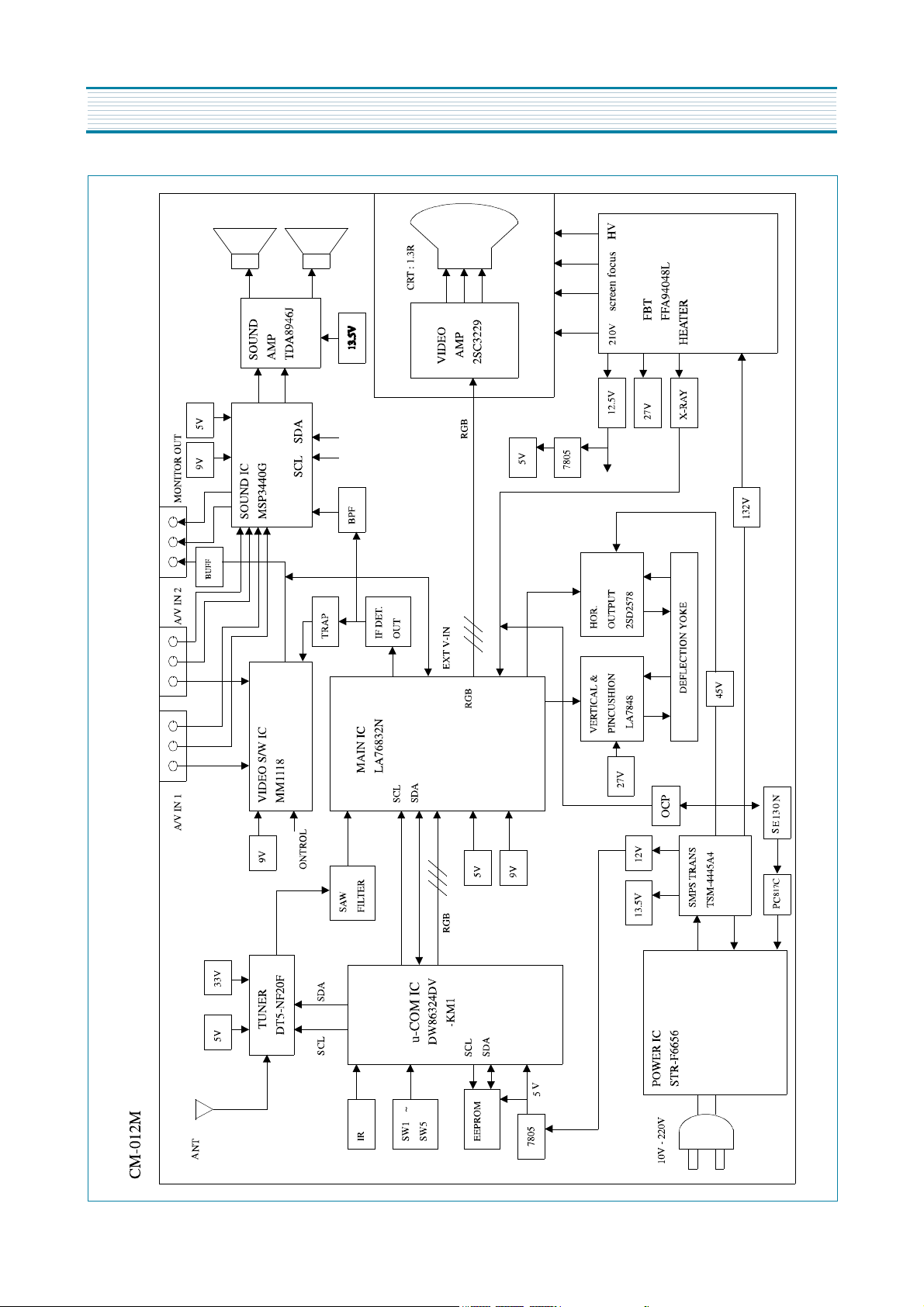
CIRCUIT BLOCK DIAGRAM
3
Page 5
ALIGNMENT INSTRUCTION
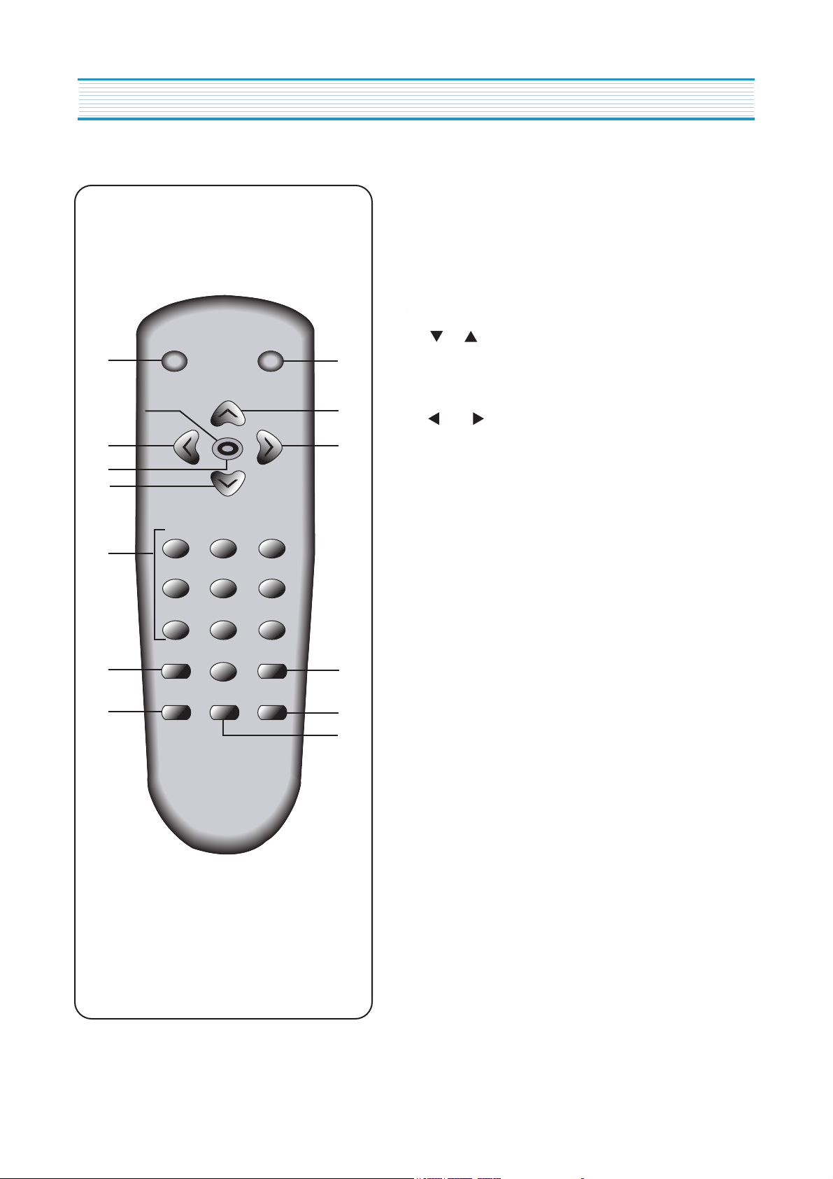
Your Remote Control(R-43A05)
1. POWER
use this button to turn your TV on or off.
2. MUTE
Use to turn the TV's sound on and off.
10
POWERMUTE
2
1
3. CH
Use these buttons to change your TV's volume, to
activate selections in the menu system.
MENU
4
5
VOL VOL
3
CH
3
4
4. VOL
Use thesebuttons to change your TV's volume, to
activate selections in the meny system, or to change
audio and video settings.
5. MENU
1 2 3
Use this button to turn the TV's menu system on and off.
9
4 5 6
6. DISPLAY
7 8
9
Use this button to display the channel numbeer and
status.
SLEEP PREVIOUS
6
0
11
VIDEOINPUTDISPLAY
8
7
7. INPUT
Use this button to select the TV's signal source.
8. VIDEO
Use this button to display video adjustment.
9. 0-9
Use these buttons to change channels.
10. SLEEP
Use this button to program the TV to turn off after a
certain time.
11. PREVIOUS
Use this button to return to the previous channel you
were watching.
4
Page 6
ALIGNMENT INSTRUCTIONS
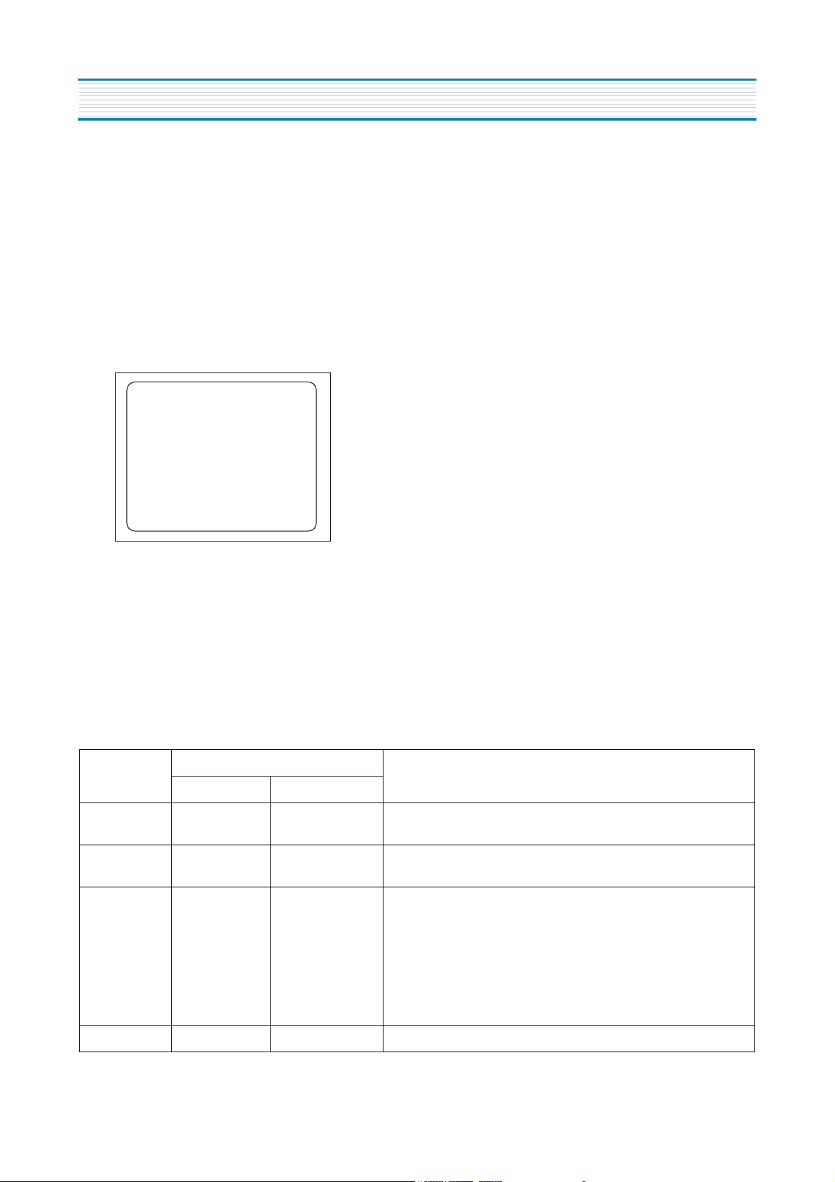
1. SERVICE MODE ADJUSTMENTS
Follow the steps below whenever service adjustment is required. See Table- A and Table- B to determine if
service adjustments are required.
1) How to enter the service mode using the user remote control.
•
Turn the set on.
•
Direct the remote control to the reception window of TV.
•
Push buttons of remote control in sequence as follows.
1 → MUTE → DISPLAY → MUTE
•
Then, the screen will appear as follows.
S2 SCRN
S5 IFC
S6 GEO
S8 W/B
S9 DP
S12 FACT
•
Using the channel up or channel down button, select the item you wish to adjust.
(The color of selected item turns into the red.)
•
Press the volume up or down button to enter in the service mode you wish to adjust.
2) How to memorize the adjusted values in the service mode.
•
Must press
DISPLAY
button the state which the screen is displaying each of service
after all adjustments are completed each of all service menu.
Table-A : Adjust the values of service mode when a part is replaced.
PART
REPLACED
I701
(U-COM)
I101
(MAIN)
I702
(EEPROM)
NECESSARY UNNECESSARY
ADJUSTMENT
O
O
Initial setting values are written from I701.
O S6 : H.PHASE/V.POSI/V.SIZE
Data is stored in I703.
ADJUSTING ITEMS
S5 : RFAGCD
S8 : RD/GD/BD/RB/GB/BB
S9 Subbrightness
menus
NOTES
CRT O Adjust items related to picture tube only.(White Balance adjustment)
5
Page 7
ALIGNMENT INSTRUCTIONS
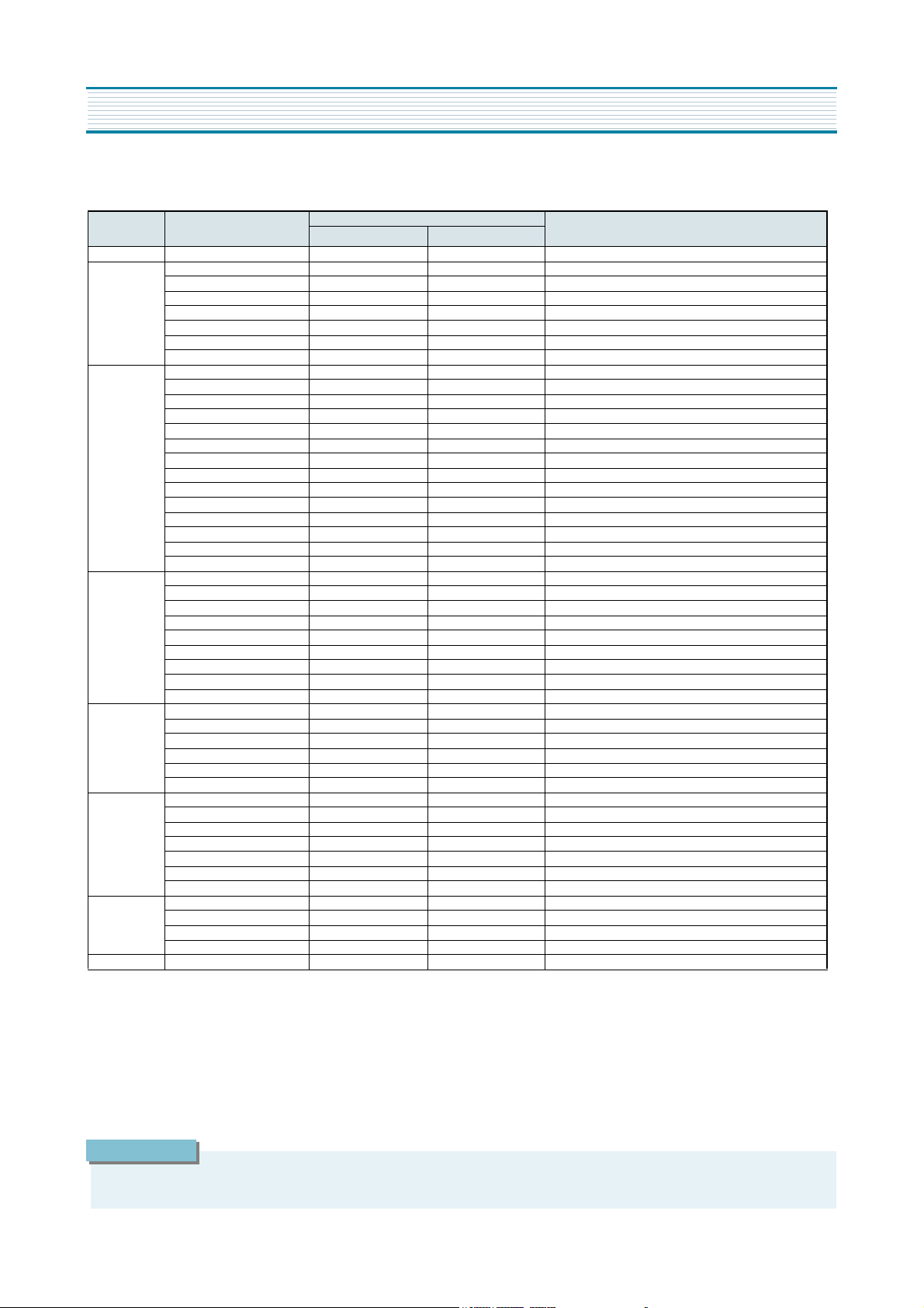
Table-B
MODE ADJUSTMENT ITEMS
S2 Screen Adjustment - -
S5
S6(4:3)
S6-2(16:9)
S8
S9
S11
S12 Forwarding Mode - Factory initialization
IF CONTROL
RF AGC DELAY * 20 0 ~63 Align RF AGC threshold
AGC POINT 3.75 3.25~4.0 Select AGC reference voltage
A/D VALUE - FM/AM PRESCALE 18 0~255 Must be set to 18
SCART PRESCALE 18 0~255 Must be set to 18
MONITOR VOLUME 119 0~255 Must be set to 119
H-CENTER * 11 0~31 Align sync to flyback pulse,using internal cross pattern(s11)
V-CENTER * 22 0~63 Align vertical DC bias,using internal cross pattern(s11)
V-LIN * 13 0~31 Must be set to 13
H-SIZE * 27 0~63 Align sync to flyback pulse,using internal cross pattern(s11)
V-SIZE * 96 0~127 Align vertical amplitude,using internal cross pattern(s11)
V-S 12 0~31 Must be set to 12
V-SIZE-C 7 0~7 Must be set to 7
P-CUSHION * 30 0~63 Align pincution,using internal cross pattern(s11)
TILT * 37 0~63 Align tilt,using internal cross pattern(s11)
TOP-C 2 0~15 Must be set to 2
BOT-C 3 0~15 Must be set to 3
H-CENTER(60-50Hz) * 5 0~31 Must be set to 5
V-CENTER(60-50Hz) * 8 0~63 Must be set to 8
V-LIN(60-50Hz) * 0 0~31 Must be set to 0
WVPOS * 22 0~63 Align vertical DC bias,using internal cross pattern(s11)
WVPOS(60-50Hz) * 8 0~63 Must be set to 8
W-V-SIZE * 48 0~127 Align vertical amplitude,using internal cross pattern(s11)
W-V-LIN * 13 0~31 Must be set to 13
W-V-S 12 0~31 Must be set to 12
W-P-CUSHIO * 17 0~63 Align pincution,using internal cross pattern(s11)
W-TILT * 37 0~63 Align tilt,using internal cross pattern(s11)
W-TOP-C 0 0~15 Must be set to 0
W-TOP-C 2 0~15 Must be set to 2
R-DRIVE * 63 0~127 Align red out AC level
G-DRIVE * 15 0~15 Must be set to 15
B-DRIVE * 63 0~127 Align blue out AC level
R-BIAS * 127 0~255 Align red out DC level
G-BIAS * 160 0~255 Must be set to 160
B-BIAS * 127 0~255 Align blue out DC level
SUB-BRIGHT * 75 0~127 Align common RGB DC level
DP-CONTRAST 27 0~27
DP-SHARPNESS 5 0~30
DP-COLOR 27 0~27
DP-TINT 38 0~77
VIDEO LEVEL 7 0~7
FM LEVEL 30 0~31
internal black - - Display internal black pattern
internal 100% white - - Display internal 100% white
internal 60% white - - Display internal 60% white
internal cross pattern - - Display internal cross pattern
INITIAL RANGE
DATA
REMARKS
*
indicates the items with different settings each of sets
2. ASSEMBLY ADJUSTMENTS
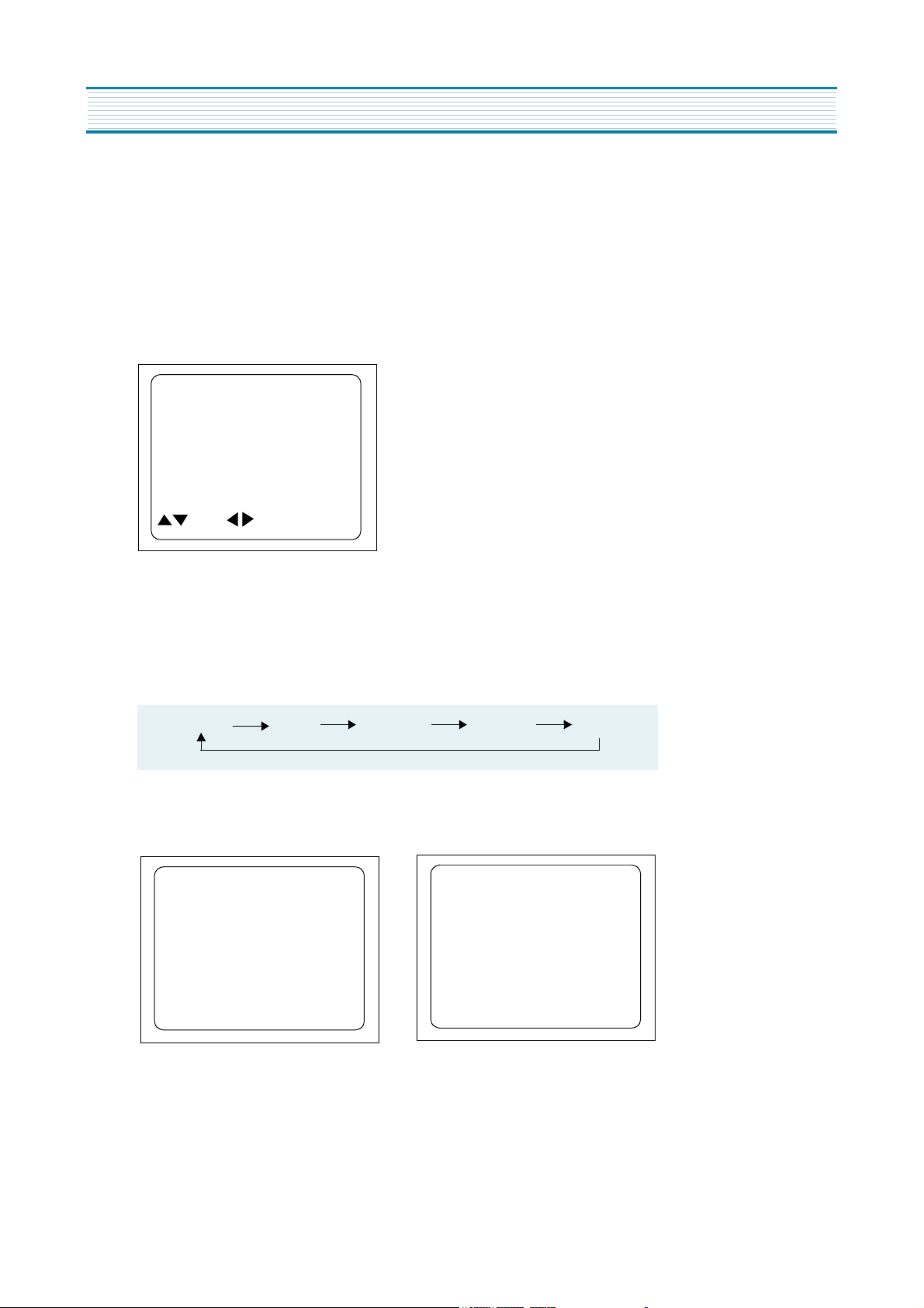
1) SCREEN ADJUSTMENT (S2)
•
Enter the service mode and select service adjustment S2.
•
You can see the one horizontal line on the screen.
•
Adjust the Screen Control Volume (located on FBT) so that the horizontal line onscreen may be disappeared.
•
Press the volume up or down button to exit in the screen adjustment mode.
CAUTION
IN THE SCREEN ADJUSTMENT MODE, DONT PRESS OTHER BUTTONS EXCEPT VOLUME UP OR DOWN BUTTON.
6
Page 8
2) FOCUS ADJUSTMENT
•
Turn in a local station and adjust the Focus Control knob (located on FBT) for best picture
details at high light condition.
3) RF AGC DELAY ADJUSTMENT (S5)
•
Receive a good local channel.
•
Enter the service mode and select service adjustment S5.
•
You can see the OSD as shown in below.
IF CONTROL
AUTO RFAGC START
RFAGC DELAY 2.0
AGC POINT 3.75
A/D VALUE 9DH
FM/AM PRESCALE 18
SCART PRESCALE 18
MONITOR VOLUME 119
MOVE ADJUST RECALL : SET
ALIGNMENT INSTRUCTIONS
•
Select RFAGCD item, press the volume up or down button until noise or beat in picture disappears.
•
Press the DISPLAY button to memorize the data.
4) GEOMETRIC ADJUSTMENTS (S6)
•
Enter the service mode and select service adjustment S11.
•
Whenever you select the “S11” using the volume up or down button, the screen is changing like this.
NORMAL BLACK WHITE100 WHITE60 CROSS
•
Using the volume up or down button, select internal cross pattern.
•
Select service adjustment S6
•
You can see the OSD as shown in below.
H-CENTER 11
V-CENTER 22
V-LIN 13
H-SIZE 27
V-SIZE 96
V-S 12
V-SIZE-C 7
PIN 30
TILT 37
TOP-C 2
BOT-C 3
WVPOS 48
W-VSIZE 22
W-VLIN 13
W-VS 12
W-PCUTION 17
W-TILT 37
W-TOPC 0
W-BOTC 2
4-1. Horizontal Position Adjustment
•
Select H-CENTER item, adjust H-CENTER data value to obtain proper horizontal centering of the
internal cross pattern at the left and right of the screen.
4-2. Vertical Position Adjustment
•
Select V-CENTER item, adjust V-CENTER data value to center the raster properly on the screen.
7
Page 9
ALIGNMENT INSTRUCTIONS
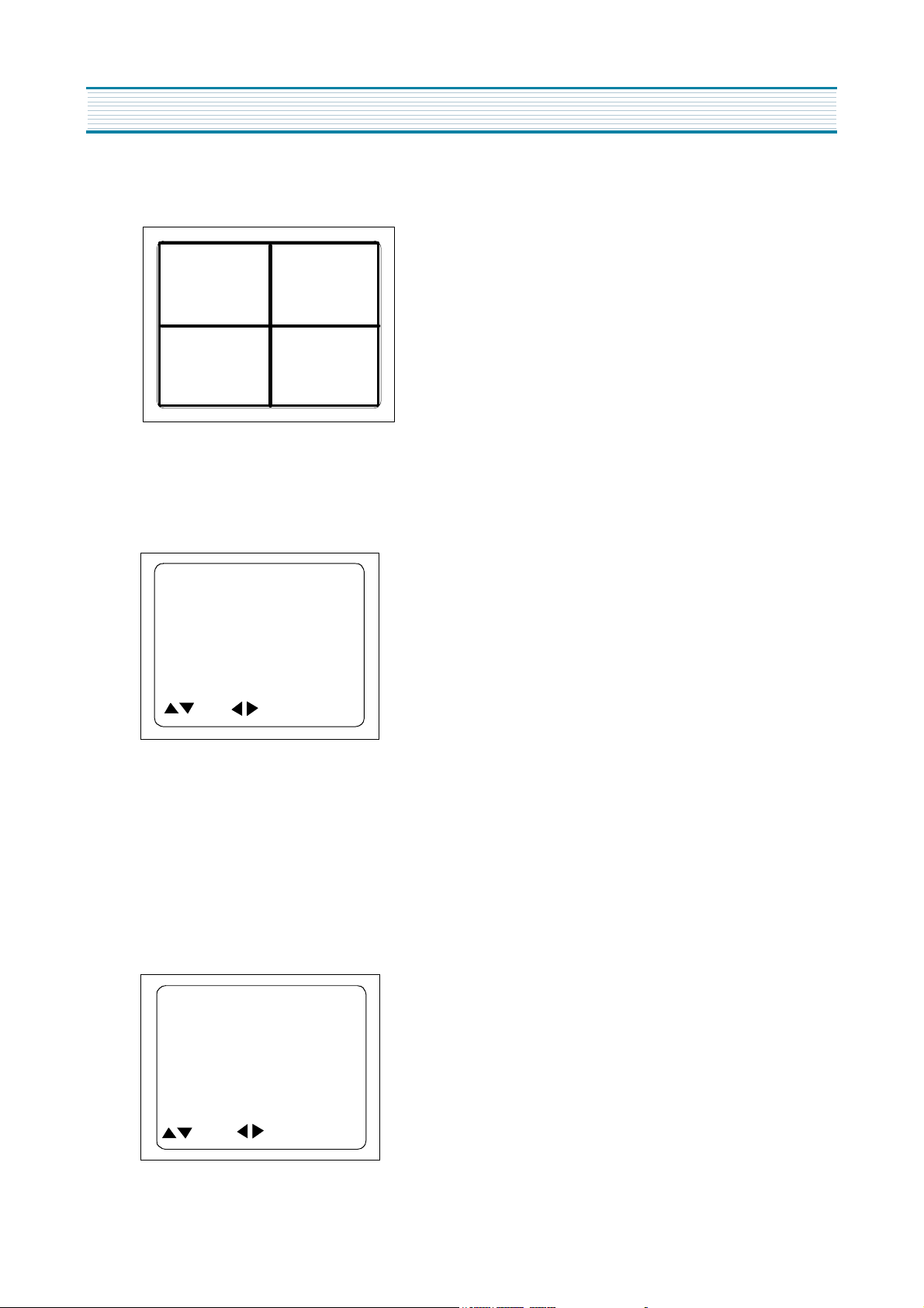
4-3. Vertical Size Adjustment
•
Select “V.SIZE” item, adjust “V.SIZE” data value to proper vertical size as follows.
5) WHITE BALANCE ADJUSTMENT(S8)
•
Receive a good local channel.
•
Enter the service mode and select service adjustment S8.
•
You can see the OSD as shown in below.
RD 63
GD 15
BD 63
RB 127
GB 160
BB 127
MOVE ADJUST RECALL : SET
•
Using volume up or volume down, adjust service adjustment data of RD/GD/BD and RB/GB/BB until a good gray
scale with normal whites is obtained.ALIGNMENT INSTRUCTIONS
•
Press the DISPLAY button to memorize the data.
6) DIGITAL PRESET(D.P) ADJUSTMENTS(S9)
SUBBRIGHTNESS ADJUSTMENT
•
Receive a good local channel.
•
Enter the service mode and select service adjustment S9.
•
You can see the OSD as shoown in below.
SUB BRIGHTNESS 75
DP-CONTRAST 27
DP-SHARPNESS 5
DP-COLOR 27
DP-TINT 38
VIDEO LEVEL 7
FM LEVEL 30
MOVE ADJUST RECALL : SET
8
Page 10

•
Select Subbrightness item, adjust Subbrightness data value
•
Press the DISPLAY button to memorize the data.
CONTRAST
•
Fixed value = 27
TINT
•
Fixed value = 38
COLOR
•
Fixed value = 27
7) FACTORY OUTGOING MODE (S12 : FACT)
•
If you select the S12, then the set becomes factory outgoing status.
•
You can see the OSD “outgoing OK”
ALIGNMENT INSTRUCTIONS
to obtain normal
brightness level.
9
Page 11
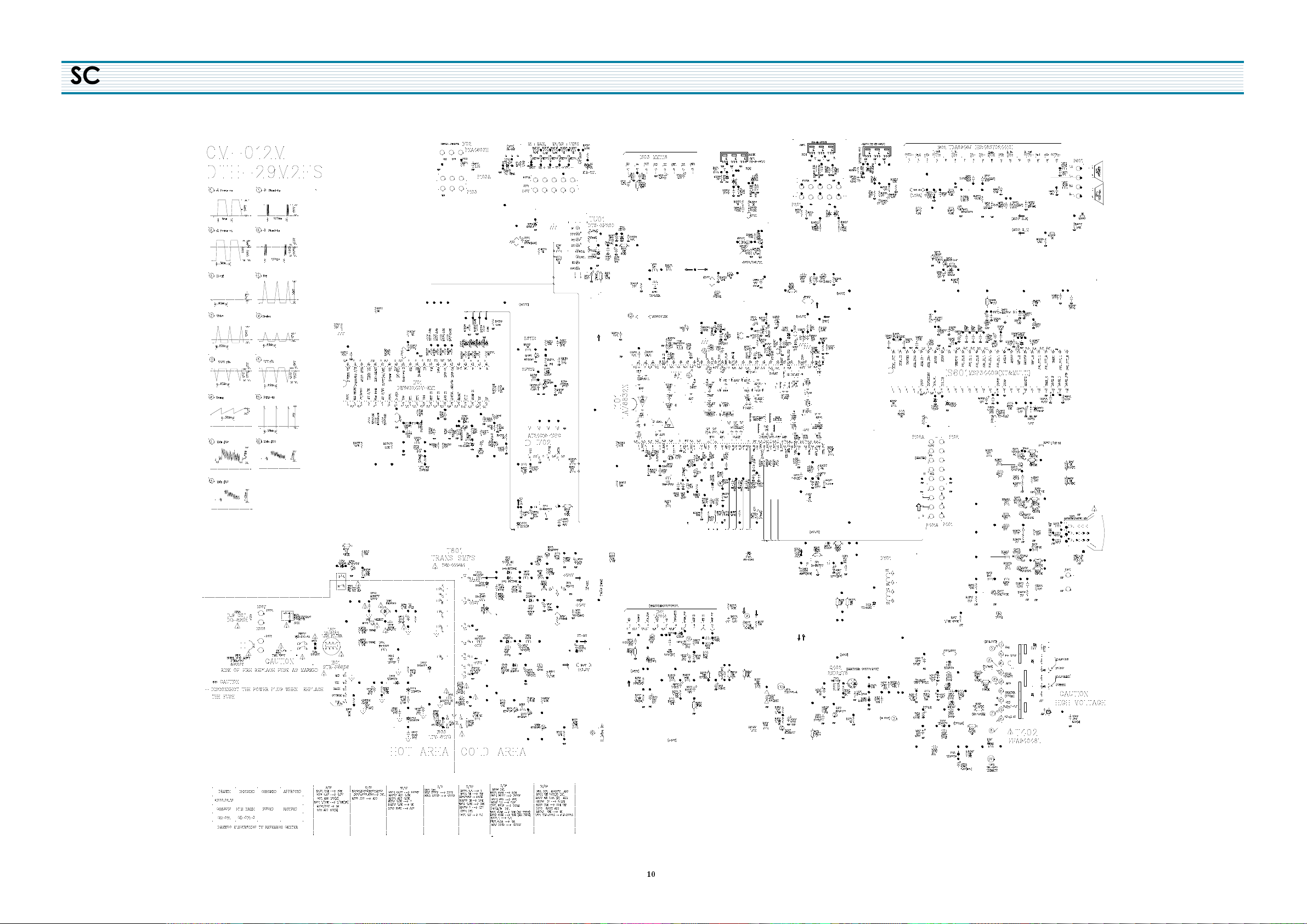
6&+(0$7,&',$*5$0
6(5926<6&21&(&&,5&8,7',$*5$07'(&.
&,5&8,7',$*5$0
Page 12
ELECTRICAL PARTS LIST
CAUTION
!
“ “ is a safety part, so it must be used the same part.
R
“ ” is a recommendable part for essential stock.
LOC PART CODE PART NAME PART DESCRIPTION REMARK
ZZ100 48B4343A05 TRANSMITTER REMOCON R-43A05 (AA)
ZZ110 PTACPWD403 ACCESSORY AS DTH-29M2FS
30 4850Q00810 BATTERY R6P/LN
M821 4858213800 BAG INSTRUCTION L.D.P.E T0.05X250X400
ZZ120 PTBCSHD403 COVER BACK AS DTH-29M2FS
M211 4852157100 COVER BACK FR HIPS BK
M591 4855934100 DECO AV PVC CL T0.2
M781 4857817630 CLOTH BLACK FELT 400X20X0.7
M782 4857817612 CLOTH BLACK FELT 250X20X0.7
ZZ130 PTPKCPJ811 PACKING AS DTQ-29M2
M641 6520010100 STAPLE PIN 18M/M J D O
M681 4856812400 BAND 18MM X 3M
M801 4858057600 BOX CARTON DW-3
M811 4858194600 PAD A EPS
M821 4858215600 BAG P.E PE FOAM t0.5x1600x1270
ZZ131 58G0000145 COIL DEGAUSSING DC-29S2
ZZ132 48519A4210 CRT GROUND NET 2901H-1015-2P
ZZ140 PTCACAD403 CABINET AS DTH-29M2FS
40 2TF01612CL TAPE FILAMENT 12MMX55ME CLEAR
M191A 7178301011 SCREW TAPPTITE TT2 WAS 3X10 MFZN
M201A 4856015800 SCREW CRT FIX L=27
M201B 4856215402 WASHER RUBBER CR T2.0
M201C 4856013610 SCREW SPKR FIX L=16 A=17
M201D 4856816300 CLAMP WIRE NYLON 6 (V0)
M211A 7172401612 SCREW TAPPTITE TT2 TRS 4X16 MFZN BK
M211B 7172401612 SCREW TAPPTITE TT2 TRS 4X16 MFZN BK
M211C 7172401612 SCREW TAPPTITE TT2 TRS 4X16 MFZN BK
M352 4853535600 HOLDER CORD NYROLN 66
M481 4854857401 BUTTON POWER A ABS GY
M481A 4856715600 SPRING SWPA PIE 0.4
M541 4855419800 SPEC PLATE ART 150
M561 48556174SD MARK BRAND SILVER DIA-CUTTING
M591 4855934202 DECO PLATE ABS GY
M591A 7172401612 SCREW TAPPTITE TT2 TRS 4X16 MFZN BK
M592 4855934601 DECO EYE ABS BLUE
M592A 7178301212 SCREW TAPPTITE TT2 WAS 3X12 MFZN BK
M593 4855934100 DECO AV PVC CL T0.2
M781 4857818702 CLOTH BLACK FELT T0.7 L=350 W=15
M782 4857821102 CLOTH BLACK FELT 340X10X1.5
M901 2224050027 BOND SILICON TSK-5370
SP01A 7172401212 SCREW TAPPTITE TT2 TRS 4X12 MFZNCK
SP02A 7172401212 SCREW TAPPTITE TT2 TRS 4X12 MFZNCK
2
V901 4859629662 CRT A68KTB259X010 M16
2
ZZ200 PTFMSJD403 MASK FRONT AS DTH-29M2FS
M201 4852075201 MASK FRONT HIPS GY
LOC PART CODE PART NAME PART DESCRIPTION REMARK
R
M251A 4852541301 GRILL R PS T0.45
M251B 4852541401 GRILL L PS T0.45
ZZ202 PTSPPWD403 SPEAKER AS DTH-29M2FS
P601A 4850704S31 CONNECTOR YH025-04+35098+ULW=800
SP01 4858311110 SPEAKER 12W 8 OHM SP-58126F
SP02 4858311110 SPEAKER 12W 8 OHM SP-58126F
ZZ204 PTJASWJ811 PCB JACK AS DTQ-29M2
JA02 4859105450 JACK PIN BOARD YSC03P-4120-9S
M112 4851114001 PANEL AV ASSY 2326801+5934300
M112A 7178301011 SCREW TAPPTITE TT2 WAS 3X10 MFZN
M684 4856812001 TIE CABLE NYLON66 DA100
P201A 4850705S04 CONNECTOR YH025-05+YST025+ULW=400
ZZ200 PTJAJAJ811 PCB JACK AXIAL AS DTQ-29M2
A001 4859802917 PCB JACK 79.05X27.3(197X246/14)S1B
CC608 CCZB1H102K C CERA 50V B 1000PF K (AXIAL)
CCS07 CCZB1H102K C CERA 50V B 1000PF K (AXIAL)
!
RC636 RD-AZ473J- R CARBON FILM 1/6 47K OHM J
!
RCS33 RD-AZ473J- R CARBON FILM 1/6 47K OHM J
ZZ210 PTUNSWJ811 PCB UNION AS DTQ-29M2
A001 4859806060 PCB UNION 246X35(246X246/6) S1B
DF01 DKLR114L-- LED KLR114L
IF01 1SR9HP---- IC PREAMP SR-9HP
IF02 1PNA4603H- IC PHOTO SENSOR PNA4603H
M191 4851942400 BUTTON CTRL 4946801+5540901
P103A 4850703S19 CONNECTOR YH025-03+YST025+ULW=300
P701A 4850705S02 CONNECTOR YH025-05+YST025+ULW=200
ZZ200 PTUNJBJ811 PCB UNION M-10 AS DTQ-29M2
ZZ200 PTUNJRJ811 PCB UNION RADIAL AS DTQ-29M2
SW702 5S50101Z90 SW TACT THVV502GDA
SW703 5S50101Z90 SW TACT THVV502GDA
SW704 5S50101Z90 SW TACT THVV502GDA
SW705 5S50101Z90 SW TACT THVV502GDA
SW706 5S50101Z90 SW TACT THVV502GDA
ZZ200 PTUNJAJ811 PCB UNION AXIAL AS DTQ-29M2
C701 CBZF1H104Z C CERA SEMI 50V F 0.1MF Z
CC716 CCZF1H103Z C CERA 50V F 0.01MF Z
CF01 CCZF1H103Z C CERA 50V F 0.01MF Z
D721 DMTZJ5R6B- DIODE ZENER MTZJ 5.6B
R701 RD-AZ240J- R CARBON FILM 1/6 24 OHM J
RC742 RD-AZ222J- R CARBON FILM 1/6 2.2K OHM J
RC746 RD-AZ152J- R CARBON FILM 1/6 1.5K OHM J
RC747 RD-AZ392J- R CARBON FILM 1/6 3.9K OHM J
RC750 RD-AZ102J- R CARBON FILM 1/6 1K OHM J
R
!
RC751 RD-AZ102J- R CARBON FILM 1/6 1K OHM J
R
RF01 85801065GY WIRE COPPER AWG22 1/0.65 TIN COATING
R
R
R
R
11
Page 13

ELECTRICAL PARTS LIST
LOC PART CODE PART NAME PART DESCRIPTION REMARK
ZZ290 PTMPMSD403 PCB MAIN MANUAL AS DTH-29M2FS
10 2TM18006BE TAPE MASKING 6.2X500
20 2TM10006LB TAPE MASKING 3M #232-MAP-C 6.2X2000M
30 2291050615 FLUX SOLDER DF-2012U
40 2291050301 FLUX SOLVENT IM-1000
50 2291140501 WAX COVER
90 2291051001 FLUX KILLER KFT-7
C307 CEYF1E332V C ELECTRO 25V RSS 3300MF (16X31.5)
C408 CMYH3C912J C MYLAR 1.6KV BUP 9100PF J
C409 CMYH3C822J C MYLAR 1.6KV BUP 8200PF J
C410 CMYE2G273J C MYLAR 400V PU 0.027MF J
C423 CMYE2G514J C MYLAR 400V PU 0.51MF J
C430 CEYD1H689W C ELECTRO 50V RHD 6.8MF (16X35.5)
C634 CEYF1V222V C ELECTRO 35V RSS 2200MF (16X31.5)
C803 CL1JB3104M C LINE ACROSS AC250V 0.1MF M ECQ-UV WRL
C804 CEYN2G181P C ELECTRO 400V LHS 180MF (25X35)
C809 CH1BFE472M C CERA AC AC400V 4700PF M U/C/V
C811 CH1BFE472M C CERA AC AC400V 4700PF M U/C/V
C813 CEYN2D221T C ELECTRO 200V FWS 220MF (22X30)
C821 CEYF1E332V C ELECTRO 25V RSS 3300MF (16X31.5)
C824 CBYB3D102K C CERA SEMI 2KV BL(N) 1000PF K
C831 CEYF1V332V C ELECTRO 35V RSS 3300MF (18X35.5)
C908 4SG0D00103 SPARK GAP S-23 900V-1.5KV
C909 4SG0D00103 SPARK GAP S-23 900V-1.5KV
C910 4SG0D00103 SPARK GAP S-23 900V-1.5KV
D402 DDG3------ DIODE DG3
D403 DRGP30J--- DIODE RGP30J
D801 DPBS606GU- DIODE BRIDGE PBS606G
D810 DBYT56K--- DIODE BYT56K
D811 DBYT56K--- DIODE BYT56K
D815 DRGP30J--- DIODE RGP30J
DY1 4859240120 CONN WAFER YFW500-06
F801 5FSGB4022L FUSE GLASS TUBE SEMKO TL 4A 250V MF51
I101 1LA76832N- IC MAIN LA76832N
I301 PTC2SW8202 HEAT SINK ASS‘Y 1LA7848--- + 7174300811
1 1LA7848--- IC VERTICAL LA7848
0000A 4857028202 HEAT SINK AL EX BK
0000B 7174300811 SCREW TAPPTITE TT2 RND 3X8 MFZN
I401 1KA7805--- IC REGULATOR KA7805
I503 1MM1118--- IC A/V SWITCH MM1118
I602 PTA2SW4410 HEAT SINK ASS‘Y 1TDA8946J- + 7174300811
1 1TDA8946J- IC AUDIO TDA8946J
0000A 4857024410 HEAT SINK AL EX (NO ANODIZING)
0000B 7174300811 SCREW TAPPTITE TT2 RND 3X8 MFZN
0000C 4856815900 CLAMP WIRE EGI T0.4+PVC COATING
I701 1DW8632KM1 IC MICOM DW863240V-KM1(5V37)
I702 1AT24C16PC IC AT24C16-10PC
I703 1KA7805--- IC REGULATOR KA7805
I801 PTB2SW6110 HEAT SINK ASS‘Y 1STRF6656- + 7174300811
LOC PART CODE PART NAME PART DESCRIPTION REMARK
I801 1STRF6656- IC POWER STR-F6656
I801A 4857026110 HEAT SINK AL EX
I801B 7174300811 SCREW TAPPTITE TT2 RND 3X8 MFZN
I802 1SE130N--- IC SE130N
I803 1KP1010C-- IC PHOTO COUPLER KP-1010C
I805 TX0202DA-- THYRISTOR X0202DA1BA2
IS601 1MSP3440B6 IC AUDIO MSP3440G-B6
IS603 1KA7805--- IC REGULATOR KA7805
JA01 4859110050 JACK PIN BOARD PH-JB-9614D
!
JAS03 4859110050 JACK PIN BOARD PH-JB-9614D
!
!
L105 58N0000042 COIL VCO TRF-V008
L111 58C5580019 COIL CHOKE TRF-9225 (0.55UH)
!
L403 58H0000047 COIL H-LINEARITY TRL-190D
L404 58C7070085 COIL CHOKE TLN-3062A
L801 5PLF3024-0 FILTER LINE LF-3024
!
M371A 4853747800 RETA PCB NYLON 66
!
R
M683 4856812001 TIE CABLE NYLON66 DA100
!
P102A 4850704S04 CONNECTOR YH025-04+YST025+ULW=400
!
P401A 4850705S04 CONNECTOR YH025-05+YST025+ULW=400
!
P801 4859242220 CONN WAFER YFW800-02
P802 4859242220 CONN WAFER YFW800-02
P901 4859238620 CONN WAFER YPW500-02
!
PWC1 4859909110 CORD POWER AS LP-16+H03VVH2-F+HOU=2600
Q402 PTB2SW4503 HEAT SINK ASS‘Y T2SD2578-- + 7174301011
1 T2SD2578-- TR 2SD2578
0000A 4857024503 HEAT SINK AL EX
R
0000B 7174301011 SCREW TAPPTITE TT2 RND 3X10 MFZN
R
R
Q403 TKTC3208-- TR KTC3208
Q801 TKTA968AY- TR KTA968AY
Q901 PTL2SW6900 HEAT SINK ASS‘Y TKTC3229-- + 7174301011
1 TKTC3229-- TR KTC 3229
0000A 4857026900 HEAT SINK AL EX
!
0000B 7174301011 SCREW TAPPTITE TT2 RND 3X10 MFZN
R
Q902 PTL2SW6900 HEAT SINK ASS‘Y TKTC3229-- + 7174301011
1 TKTC3229-- TR KTC 3229
0000A 4857026900 HEAT SINK AL EX
R
0000B 7174301011 SCREW TAPPTITE TT2 RND 3X10 MFZN
Q903 PTL2SW6900 HEAT SINK ASS‘Y TKTC3229-- + 7174301011
1 TKTC3229-- TR KTC 3229
0000A 4857026900 HEAT SINK AL EX
R
0000B 7174301011 SCREW TAPPTITE TT2 RND 3X10 MFZN
R
R801 DPC7R0M290 POSISTOR 2322 662 96709
R
R802 RX10T229KS R CEMENT 10W 2.2 OHM K TRIPOD SMAL
R825 RM02Y158J- R METAL FLAT 2W 0.15 OHM J
SCT01 4859303830 SOCKET CRT ISHG94S
SF101 5PTSF5241P FILTER SAW TSF5241P
R
SW707 5S40202080 SW PUSH PS3-22 (PCB)
R
T401 5TD0000018 TRANS DRIVE THD-120
T402 50H0000189 FBT FFA94048L
R
!
!
!
!
!
!
!
!
!
!
!
12
Page 14

ELECTRICAL PARTS LIST
LOC PART CODE PART NAME PART DESCRIPTION REMARK
T402A 7178301212 SCREW TAPPTITE TT2 WAS 3X12 MFZN BK
T801 50M4445A4- TRANS SMPS TSM-4445A4
TU01 4859720130 TUNER VARACTOR DT5-NF20D
X702 5XYR03276C CRYSTAL QUARTZ C-001R 32.768000KHZ 20PPM
XS601 5XE18R432E CRYSTAL QUARTZ HC-49/U 18.43200MHZ 30PPM
Y801 5SC0101325 SW RELAY HR-CR7 DC12V
Z501 5PYXT4R5MB FILTER CERA XT 4.5MB
ZZ200 PTMPJ2D403 PCB CHIP MOUNT B AS DTH-29M2FS
CC102 HCFK103ZCA C CHIP CERA 50V Y5V 0.01MF Z 2012
CC111 HCFK104ZCA C CHIP CERA 50V Y5V 0.1MF Z 2012
CC112 HCFK103ZCA C CHIP CERA 50V Y5V 0.01MF Z 2012
CC113 HCFK104ZCA C CHIP CERA 50V Y5V 0.1MF Z 2012
CC151 HCFK104ZCA C CHIP CERA 50V Y5V 0.1MF Z 2012
CC154 HCFK104ZCA C CHIP CERA 50V Y5V 0.1MF Z 2012
CC180 HCFK103ZCA C CHIP CERA 50V Y5V 0.01MF Z 2012
CC206 HCFK104ZCA C CHIP CERA 50V Y5V 0.1MF Z 2012
CC209 HCFK104ZCA C CHIP CERA 50V Y5V 0.1MF Z 2012
CC401 HCQK181JCA C CHIP CERA 50V CH 180PF J 2012
CC450 HCFK103ZCA C CHIP CERA 50V Y5V 0.01MF Z 2012
CC501 HCQK160JCA C CHIP CERA 50V CH 16PF J 2012
CC502 HCFK104ZCA C CHIP CERA 50V Y5V 0.1MF Z 2012
CC528 HCBK102KCA C CHIP CERA 50V X7R 1000PF K 2012
CC574 HCQK300JCA C CHIP CERA 50V CH 30PF J 2012
CC577 HCQK300JCA C CHIP CERA 50V CH 30PF J 2012
CC578 HCQK300JCA C CHIP CERA 50V CH 30PF J 2012
CC579 HCQK300JCA C CHIP CERA 50V CH 30PF J 2012
CC701 HCBK103KCA C CHIP CERA 50V X7R 0.01MF K 2012
CC708 HCQK120JCA C CHIP CERA 50V CH 12PF J 2012
CC720 HCBK102KCA C CHIP CERA 50V X7R 1000PF K 2012
CC722 HCFK103ZCA C CHIP CERA 50V Y5V 0.01MF Z 2012
CC723 HCBK103KCA C CHIP CERA 50V X7R 0.01MF K 2012
CC741 HCQK221JCA C CHIP CERA 50V CH 220PF J 2012
CC752 HCQK180JCA C CHIP CERA 50V CH 18PF J 2012
CC754 HCFK104ZCA C CHIP CERA 50V Y5V 0.1MF Z 2012
CC757 HCBK333KCA C CHIP CERA 50V X7R 0.033MF K 2012
CC777 HCFK103ZCA C CHIP CERA 50V Y5V 0.01MF Z 2012
CC821 HCFK104ZCA C CHIP CERA 50V Y5V 0.1MF Z 2012
CCP01 HCBK103KCA C CHIP CERA 50V X7R 0.01MF K 2012
CCP53 HCFK103ZCA C CHIP CERA 50V Y5V 0.01MF Z 2012
CCP54 HCFK103ZCA C CHIP CERA 50V Y5V 0.01MF Z 2012
CCS01 HCQK479CCA C CHIP CERA 50V CH 4.7PF C 2012
CCS02 HCQK479CCA C CHIP CERA 50V CH 4.7PF C 2012
CCS03 HCFK103ZCA C CHIP CERA 50V Y5V 0.01MF Z 2012
CCS04 HCFK103ZCA C CHIP CERA 50V Y5V 0.01MF Z 2012
CCS05 HCQK471JCA C CHIP CERA 50V CH 470PF J 2012
CCS06 HCFK104ZCA C CHIP CERA 50V Y5V 0.1MF Z 2012
CCS10 HCFK104ZCA C CHIP CERA 50V Y5V 0.1MF Z 2012
CCS11 HCBK102KCA C CHIP CERA 50V X7R 1000PF K 2012
CCS12 HCFK104ZCA C CHIP CERA 50V Y5V 0.1MF Z 2012
LOC PART CODE PART NAME PART DESCRIPTION REMARK
CCS13 HCFK104ZCA C CHIP CERA 50V Y5V 0.1MF Z 2012
CCS16 HCQK471JCA C CHIP CERA 50V CH 470PF J 2012
R
!
CCS17 HCQK471JCA C CHIP CERA 50V CH 470PF J 2012
R
R
CCS18 HCFK104ZCA C CHIP CERA 50V Y5V 0.1MF Z 2012
CCS21 HCBK103KCA C CHIP CERA 50V X7R 0.01MF K 2012
R
CCS22 HCBK103KCA C CHIP CERA 50V X7R 0.01MF K 2012
R
CCS24 HCBK103KCA C CHIP CERA 50V X7R 0.01MF K 2012
CCS25 HCQK471JCA C CHIP CERA 50V CH 470PF J 2012
CCS26 HCBK102KCA C CHIP CERA 50V X7R 1000PF K 2012
CCS27 HCBK102KCA C CHIP CERA 50V X7R 1000PF K 2012
CCS28 HCFK104ZCA C CHIP CERA 50V Y5V 0.1MF Z 2012
CCS29 HCBK102KCA C CHIP CERA 50V X7R 1000PF K 2012
CCS90 HCBK103KCA C CHIP CERA 50V X7R 0.01MF K 2012
CCS91 HCBK103KCA C CHIP CERA 50V X7R 0.01MF K 2012
RC103 HRFT153JCA R CHIP 1/10 15K OHM J 2012
RC104 HRFT104JCA R CHIP 1/10 100K OHM J 2012
RC105 HRFT153JCA R CHIP 1/10 15K OHM J 2012
RC154 HRFT473JCA R CHIP 1/10 47K OHM J 2012
RC156 HRFT473JCA R CHIP 1/10 47K OHM J 2012
RC165 HRFT472JCA R CHIP 1/10 4.7K OHM J 2012
RC208 HRFT331JCA R CHIP 1/10 330 OHM J 2012
RC219 HRFT123JCA R CHIP 1/10 12K OHM J 2012
RC225 HRFT331JCA R CHIP 1/10 330 OHM J 2012
RC228 HRFT331JCA R CHIP 1/10 330 OHM J 2012
RC229 HRFT331JCA R CHIP 1/10 330 OHM J 2012
RC230 HRFT331JCA R CHIP 1/10 330 OHM J 2012
RC302 HRFT473JCA R CHIP 1/10 47K OHM J 2012
RC303 HRFT562JCA R CHIP 1/10 5.6K OHM J 2012
RC306 HRFT623JCA R CHIP 1/10 62K OHM J 2012
RC503 HRFT132JCA R CHIP 1/10 1.3K OHM J 2012
RC512 HRFT241JCA R CHIP 1/10 240 OHM J 2012
RC557 HRFT302JCA R CHIP 1/10 3K OHM J 2012
RC559 HRFT331JCA R CHIP 1/10 330 OHM J 2012
RC562 HRFT914JCA R CHIP 1/10 910KOHM J 2012
RC567 HRFT103JCA R CHIP 1/10 10K OHM J 2012
RC570 HRFT103JCA R CHIP 1/10 10K OHM J 2012
RC601 HRFT243JCA R CHIP 1/10 24K OHM J 2012
RC602 HRFT224JCA R CHIP 1/10 220K OHM J 2012
RC603 HRFT392JCA R CHIP 1/10 3.9K OHM J 2012
RC632 HRFT153JCA R CHIP 1/10 15K OHM J 2012
RC634 HRFT202JCA R CHIP 1/10 2K OHM J 2012
RC635 HRFT102JCA R CHIP 1/10 1K OHM J 2012
RC704 HRFT102JCA R CHIP 1/10 1K OHM J 2012
RC705 HRFT102JCA R CHIP 1/10 1K OHM J 2012
RC707 HRFT102JCA R CHIP 1/10 1K OHM J 2012
RC711 HRFT121JCA R CHIP 1/10 120 OHM J 2012
RC728 HRFT102JCA R CHIP 1/10 1K OHM J 2012
RC730 HRFT101JCA R CHIP 1/10 100 OHM J 2012
RC732 HRFT102JCA R CHIP 1/10 1K OHM J 2012
13
Page 15

ELECTRICAL PARTS LIST
LOC PART CODE PART NAME PART DESCRIPTION REMARK
RC733 HRFT102JCA R CHIP 1/10 1K OHM J 2012
RC734 HRFT102JCA R CHIP 1/10 1K OHM J 2012
RC735 HRFT202JCA R CHIP 1/10 2K OHM J 2012
RC736 HRFT102JCA R CHIP 1/10 1K OHM J 2012
RC737 HRFT392JCA R CHIP 1/10 3.9K OHM J 2012
RC738 HRFT362JCA R CHIP 1/10 3.6K OHM J 2012
RC739 HRFT272JCA R CHIP 1/10 2.7K OHM J 2012
RC748 HRFT471JCA R CHIP 1/10 470 OHM J 2012
RC749 HRFT103JCA R CHIP 1/10 10K OHM J 2012
RC756 HRFT472JCA R CHIP 1/10 4.7K OHM J 2012
RC757 HRFT514JCA R CHIP 1/10 510K OHM J 2012
RC767 HRFT472JCA R CHIP 1/10 4.7K OHM J 2012
RC780 HRFT102JCA R CHIP 1/10 1K OHM J 2012
RC782 HRFT102JCA R CHIP 1/10 1K OHM J 2012
RC790 HRFT472JCA R CHIP 1/10 4.7K OHM J 2012
RC798 HRFT473JCA R CHIP 1/10 47K OHM J 2012
RC799 HRFT103JCA R CHIP 1/10 10K OHM J 2012
RC901 HRFT471JCA R CHIP 1/10 470 OHM J 2012
RC902 HRFT471JCA R CHIP 1/10 470 OHM J 2012
RC903 HRFT471JCA R CHIP 1/10 470 OHM J 2012
RC907 HRFT471JCA R CHIP 1/10 470 OHM J 2012
RC908 HRFT121JCA R CHIP 1/10 120 OHM J 2012
RC909 HRFT121JCA R CHIP 1/10 120 OHM J 2012
RC915 HRFT221JCA R CHIP 1/10 220 OHM J 2012
RC921 HRFT471JCA R CHIP 1/10 470 OHM J 2012
RC922 HRFT471JCA R CHIP 1/10 470 OHM J 2012
RC923 HRFT471JCA R CHIP 1/10 470 OHM J 2012
RCP02 HRFT103JCA R CHIP 1/10 10K OHM J 2012
RCP05 HRFT103JCA R CHIP 1/10 10K OHM J 2012
RCS06 HRFT102JCA R CHIP 1/10 1K OHM J 2012
RCS07 HRFT102JCA R CHIP 1/10 1K OHM J 2012
RCS08 HRFT182JCA R CHIP 1/10 1.8K OHM J 2012
RCS09 HRFT203JCA R CHIP 1/10 20K OHM J 2012
RCS11 HRFT103JCA R CHIP 1/10 10K OHM J 2012
RCS12 HRFT203JCA R CHIP 1/10 20K OHM J 2012
RCS14 HRFT473JCA R CHIP 1/10 47K OHM J 2012
RCS16 HRFT750JCA R CHIP 1/10 75 OHM J 2012
RCS30 HRFT473JCA R CHIP 1/10 47K OHM J 2012
RCS31 HRFT101JCA R CHIP 1/10 100 OHM J 2012
RCS32 HRFT473JCA R CHIP 1/10 47K OHM J 2012
RCS34 HRFT102JCA R CHIP 1/10 1K OHM J 2012
RCS37 HRFT102JCA R CHIP 1/10 1K OHM J 2012
RCS39 HRFT473JCA R CHIP 1/10 47K OHM J 2012
RCS40 HRFT473JCA R CHIP 1/10 47K OHM J 2012
RCS41 HRFT102JCA R CHIP 1/10 1K OHM J 2012
RCS78 HRFT472JCA R CHIP 1/10 4.7K OHM J 2012
RP720 HRFT472JCA R CHIP 1/10 4.7K OHM J 2012
ZZ200 PTMPJ0D403 PCB MAIN (RHU) AS DTH-29M2FS
C113 CEXF1C471V C ELECTRO 16V RSS 470MF (10X12.5)TP
LOC PART CODE PART NAME PART DESCRIPTION REMARK
C212 CEXF1C471V C ELECTRO 16V RSS 470MF (10X12.5)TP
C311 CEXF1C471V C ELECTRO 16V RSS 470MF (10X12.5)TP
C403 CEXF2C101V C ELECTRO 160V RSS 100MF (16X25) TP
C404 CEXF2E100V C ELECTRO 250V RSS 10MF (10X20) TP
C417 CEXF1V471V C ELECTRO 35V RSS 470MF (10X20) TP
C419 CEXF1V102V C ELECTRO 35V RSS 1000MF (13X25) TP
C424 CEXA2D229E C ELECTRO 200V RUL 2.2MF (10X16) TP
C425 CEXF2A470V C ELECTRO 100V RSS 47MF (10X16) TP
C433 CEXF1C471C C ELECTRO 16V RUS 470MF (10X12.5)TP
C437 CEXF1E471C C ELECTRO 25V RUS 470MF (10X16) TP
C805 CH1BEE472M C CERA AC U/C/V 2.5KV 4700PF TP
C806 CH1BEE472M C CERA AC U/C/V 2.5KV 4700PF TP
C810 CBXB3D471K C CERA SEMI 2KV BL(N) 470PF K (T)
C815 CCXB3D471K C CERA 2KV B 470PF K (TAPPING)
C816 CEXF2C470V C ELECTRO 160V RSS 47MF (13X25) TP
C819 CCXB3D102K C CERA 2KV B 1000PF K (TAPPING)
C820 CEXF1E102V C ELECTRO 25V RSS 1000MF (13X20) TP
C906 CH1BEE472M C CERA AC U/C/V 2.5KV 4700PF TP
ZZ200 PTMPJBD403 PCB MAIN M-10 AS DTH-29M2FS
10 2TM18006BE TAPE MASKING 6.2X500
P102 485923172S CONN WAFER YW025-04 (STICK)
P103 485923162S CONN WAFER YW025-03 (STICK)
P201 485923182S CONN WAFER YW025-05 (STICK)
P401 485923182S CONN WAFER YW025-05 (STICK)
P601 485923172S CONN WAFER YW025-04 (STICK)
P701 485923182S CONN WAFER YW025-05 (STICK)
R104 RS02Z472JS R M-OXIDE FILM 2W 4.7K OHM J SMALL
R401 RS02Z680JS R M-OXIDE FILM 2W 68 OHM J SMALL
R402 RS02Z680JS R M-OXIDE FILM 2W 68 OHM J SMALL
R417 RF01Z229J- R FUSIBLE 1W 2.2 OHM J (TAPPING)
R418 RF01Z229J- R FUSIBLE 1W 2.2 OHM J (TAPPING)
R419 RF02Z159J- R FUSIBLE 2W 1.5 OHM J (TAPPING)
R425 RS02Z163JS R M-OXIDE FILM 2W 16K OHM J SMALL
R810 RF01Z398K- R FUSIBLE 1W 0.39 OHM K (TAPPING)
R831 RS02Z153JS R M-OXIDE FILM 2W 15K OHM J SMALL
R837 RF02Z228K- R FUSIBLE 2W 0.22 OHM K (TAPPING)
R915 RF01Z229J- R FUSIBLE 1W 2.2 OHM J (TAPPING)
R916 RF01Z229J- R FUSIBLE 1W 2.2 OHM J (TAPPING)
ZZ200 PTMPJRD403 PCB MAIN RADIAL AS DTH-29M2FS
C106 CEXF1C101V C ELECTRO 16V RSS 100MF (6.3X11) TP
C107 CEXF1H228V C ELECTRO 50V RSS 0.22MF (5X11) TP
C108 CEXF1H101V C ELECTRO 50V RSS 100MF (8X11.5) TP
C109 CEXF1H479V C ELECTRO 50V RSS 4.7MF (5X11) TP
C114 CEXF1H109V C ELECTRO 50V RSS 1MF (5X11) TP
C116 CMXM2A333J C MYLAR 100V 0.033MF J (TP)
C117 CMXM2A103J C MYLAR 100V 0.01MF J (TP)
C201 CEXF1H108V C ELECTRO 50V RSS 0.1MF (5X11) TP
C204 CEXF1H478V C ELECTRO 50V RSS 0.47MF (5X11) TP
C205 CEXF1C101V C ELECTRO 16V RSS 100MF (6.3X11) TP
!
!
!
!
!
!
!
!
!
!
14
Page 16

ELECTRICAL PARTS LIST
LOC PART CODE PART NAME PART DESCRIPTION REMARK
C210 CEXF1E470V C ELECTRO 25V RSS 47MF (5X11) TP
C213 CEXF1H479V C ELECTRO 50V RSS 4.7MF (5X11) TP
C214 CEXF1H479V C ELECTRO 50V RSS 4.7MF (5X11) TP
C215 CEXF1H479V C ELECTRO 50V RSS 4.7MF (5X11) TP
C301 CXSL2H100D C CERA 500V SL 10PF D (TAPPING)
C303 CEXF1H100V C ELECTRO 50V RSS 10MF (5X11) TP
C304 CMXM2A224J C MYLAR 100V 0.22MF J
C305 CEXF1H101V C ELECTRO 50V RSS 100MF (8X11.5) TP
C306 CEXD1H109Q C ELECTRO 50V RT 1MF (6.3X11) TP
C308 CMXM2A153J C MYLAR 100V 0.015MF J (TP)
C309 CMXM2A473J C MYLAR 100V 0.047MF J (TP)
C310 CMXM2A103J C MYLAR 100V 0.01MF J (TP)
C312 CEXF1H100V C ELECTRO 50V RSS 10MF (5X11) TP
C313 CEXD1H109Q C ELECTRO 50V RT 1MF (6.3X11) TP
C314 CXCH1H200J C CERA 50V CH 20PF J (TAPPING)
C401 CCXB2H102K C CERA 500V B 1000PF K (TAPPING)
C402 CMXM2A104J C MYLAR 100V 0.1MF J (TP)
C405 CEXF2C109V C ELECTRO 160V RSS 1MF (6.3X11) TP
C416 CCXB2H102K C CERA 500V B 1000PF K (TAPPING)
C418 CCXB2H102K C CERA 500V B 1000PF K (TAPPING)
C420 CCXB2H102K C CERA 500V B 1000PF K (TAPPING)
C421 CEXF1H470V C ELECTRO 50V RSS 47MF (6.3X11) TP
C422 CCXB2H102K C CERA 500V B 1000PF K (TAPPING)
C429 CMXM2A104J C MYLAR 100V 0.1MF J (TP)
C501 CMXL1H105J C MYLAR 50V MEU 1MF J
C503 CEXF1C221V C ELECTRO 16V RSS 220MF (8X11.5) TP
C504 CEXF1H100V C ELECTRO 50V RSS 10MF (5X11) TP
C505 CEXF1H100V C ELECTRO 50V RSS 10MF (5X11) TP
C506 CEXF1H100V C ELECTRO 50V RSS 10MF (5X11) TP
C507 CMXM2A224J C MYLAR 100V 0.22MF J
C508 CMXM2A224J C MYLAR 100V 0.22MF J
C509 CEXF1H109V C ELECTRO 50V RSS 1MF (5X11) TP
C511 CMXM2A153J C MYLAR 100V 0.015MF J (TP)
C512 CEXF1H108V C ELECTRO 50V RSS 0.1MF (5X11) TP
C513 CEXF1H109V C ELECTRO 50V RSS 1MF (5X11) TP
C517 CMXM2A103J C MYLAR 100V 0.01MF J (TP)
C518 CEXF1H478V C ELECTRO 50V RSS 0.47MF (5X11) TP
C601 CCXF1H103Z C CERA 50V F 0.01MF Z (TAPPING)
C602 CCXF1H103Z C CERA 50V F 0.01MF Z (TAPPING)
C603 CMXL1J224J C MYLAR 63V MEU 0.22MF J (TP)
C604 CEXF1H470V C ELECTRO 50V RSS 47MF (6.3X11) TP
C606 CMXM2A104J C MYLAR 100V 0.1MF J (TP)
C607 CMXL1J224J C MYLAR 63V MEU 0.22MF J (TP)
C610 CMXL1J224J C MYLAR 63V MEU 0.22MF J (TP)
C622 CMXM2A152J C MYLAR 100V 1500PF J (TP)
C625 CMXL1J104J C MYLAR 63V MEU 0.1MF J
C669 CEXF1H100V C ELECTRO 50V RSS 10MF (5X11) TP
C702 CEXF1E101V C ELECTRO 25V RSS 100MF (6.3X11) TP
C703 CEXF1H109V C ELECTRO 50V RSS 1MF (5X11) TP
LOC PART CODE PART NAME PART DESCRIPTION REMARK
C704 CEXF1H229V C ELECTRO 50V RSS 2.2MF (5X11) TP
C705 CEXF1H109V C ELECTRO 50V RSS 1MF (5X11) TP
C709 CEXF1C221V C ELECTRO 16V RSS 220MF (8X11.5) TP
C807 CCXB1H821K C CERA 50V B 820PF K (TAPPING)
C808 CEXF1H100V C ELECTRO 50V RSS 10MF (5X11) TP
C814 CXSL2H470J C CERA 500V SL 47PF J (TAPPING)
C818 CMXL1J224J C MYLAR 63V MEU 0.22MF J (TP)
C822 CEXF1C101A C ELECTRO 16V RSM 100MF (6.3X7) TP
C825 CEXF1H229V C ELECTRO 50V RSS 2.2MF (5X11) TP
C829 CEXF1H470V C ELECTRO 50V RSS 47MF (6.3X11) TP
C830 CCXB1H152K C CERA 50V B 1500PF K (TAPPING)
C832 CEXF1H220V C ELECTRO 50V RSS 22MF (5X11) TP
C833 CEXF1H479V C ELECTRO 50V RSS 4.7MF (5X11) TP
C834 CMXM2A682J C MYLAR 100V 6800PF J (TP)
C862 CEXF1E101V C ELECTRO 25V RSS 100MF (6.3X11) TP
CP302 CEXF1H479V C ELECTRO 50V RSS 4.7MF (5X11) TP
CP517 CMXM2A103J C MYLAR 100V 0.01MF J (TP)
CP518 CEXF1C470V C ELECTRO 16V RSS 47MF (5X11) TP
CP706 CEXF1H478V C ELECTRO 50V RSS 0.47MF (5X11) TP
CS216 CEXF1H479V C ELECTRO 50V RSS 4.7MF (5X11) TP
CS217 CEXF1E221V C ELECTRO 25V RSS 220MF (8X11.5) TP
CS602 CEXF1H100V C ELECTRO 50V RSS 10MF (5X11) TP
CS605 CEXF1H100V C ELECTRO 50V RSS 10MF (5X11) TP
CS608 CEXF1H229V C ELECTRO 50V RSS 2.2MF (5X11) TP
CS609 CEXF1H100V C ELECTRO 50V RSS 10MF (5X11) TP
CS611 CEXF1H100V C ELECTRO 50V RSS 10MF (5X11) TP
CS612 CEXF1H339V C ELECTRO 50V RSS 3.3MF (5X11) TP
CS613 CMXL1J224J C MYLAR 63V MEU 0.22MF J (TP)
CS614 CMXM2A104J C MYLAR 100V 0.1MF J (TP)
CS615 CEXF1E470V C ELECTRO 25V RSS 47MF (5X11) TP
CS616 CEXF1H100V C ELECTRO 50V RSS 10MF (5X11) TP
CS617 CEXF1H100V C ELECTRO 50V RSS 10MF (5X11) TP
CS619 CEXF1H479V C ELECTRO 50V RSS 4.7MF (5X11) TP
CS621 CMXM2A152J C MYLAR 100V 1500PF J (TP)
CS623 CMXM2A104J C MYLAR 100V 0.1MF J (TP)
CS624 CMXM2A104J C MYLAR 100V 0.1MF J (TP)
CS626 CMXL1J104J C MYLAR 63V MEU 0.1MF J
CS631 CEXF1E470V C ELECTRO 25V RSS 47MF (5X11) TP
CS632 CEXF1H479V C ELECTRO 50V RSS 4.7MF (5X11) TP
CT570 CEXF1H109V C ELECTRO 50V RSS 1MF (5X11) TP
F801A 4857415001 CLIP FUSE PFC5000-0702
F801B 4857415001 CLIP FUSE PFC5000-0702
L604 58C0000096 COIL CHOKE 610G0233(470K)
L607 58C0000096 COIL CHOKE 610G0233(470K)
L805 58CX430599 COIL CHOKE AZ-9004Y 940K TP
L806 58C0000096 COIL CHOKE 610G0233(470K)
L809 58CX430599 COIL CHOKE AZ-9004Y 940K TP
L901 5CPX181J-- COIL PEAKING 180UH J (RADIAL)
Q203 TKTA1266Y- TR KTA1266Y (TP)
15
Page 17

ELECTRICAL PARTS LIST
LOC PART CODE PART NAME PART DESCRIPTION REMARK
Q407 TKTC3207-- TR KTC3207 (TP)
Q601 TKTC3198Y- TR KTC3198Y
Q602 TKTC3198Y- TR KTC3198Y
Q603 TKTA1266Y- TR KTA1266Y (TP)
Q703 TKTC3203Y- TR KTC3203-Y
Q704 TKTA1266Y- TR KTA1266Y (TP)
Q706 TKTC3198Y- TR KTC3198Y
Q802 TKTC3198Y- TR KTC3198Y
Q803 TKTC3198Y- TR KTC3198Y
Q806 TKTC3198Y- TR KTC3198Y
Q904 TKTC3198Y- TR KTC3198Y
Q905 TKTC3198Y- TR KTC3198Y
Q906 TKTC3198Y- TR KTC3198Y
Q907 TKTA1266Y- TR KTA1266Y (TP)
QP701 TKTC3198Y- TR KTC3198Y
QP702 TKTC3198Y- TR KTC3198Y
QS205 TKTC3198Y- TR KTC3198Y
R102 RN02B910JS R METAL FILM 2W 91 OHM J SMALL
R204 RN02B471JS R METAL FILM 2W 470 OHM J SMALL
R304 RN01B109JS R METAL FILM 1W 1 OHM J SMALL
R305 RN01B109JS R METAL FILM 1W 1 OHM J SMALL
R308 RN02B471JS R METAL FILM 2W 470 OHM J SMALL
R309 RN02B271JS R METAL FILM 2W 270 OHM J SMALL
R315 RN02B620JS R METAL FILM 2W 62 OHM J SMALL
R410 RN02B103JS R METAL FILM 2W 10K OHM J SMALL
R411 RN02B100JS R METAL FILM 2W 10 OHM J SMALL
R415 RN02B102JS R METAL FILM 2W 1K OHM J SMALL
R420 RN02B333JS R METAL FILM 2W 33K OHM J SMALL
R430 RN02B100JS R METAL FILM 2W 10 OHM J SMALL
R450 RN02B101JS R METAL FILM 2W 100 OHM J SMALL
R451 RN02B271JS R METAL FILM 2W 270 OHM J SMALL
R511 RN01B151JS R METAL FILM 1W 150 OHM J SMALL
R803 RN01B102JS R METAL FILM 1W 1K OHM J SMALL
R814 RN02B102JS R METAL FILM 2W 1K OHM J SMALL
R818 RN02B472JS R METAL FILM 2W 4.7K OHM J SMALL
R823 RN02B153JS R METAL FILM 2W 15K OHM J SMALL
R826 RN02B240JS R METAL FILM 2W 24 OHM J SMALL
R828 RN02B100JS R METAL FILM 2W 10 OHM J SMALL
R921 RN02B203JS R METAL FILM 2W 20K OHM J SMALL
R922 RN02B203JS R METAL FILM 2W 20K OHM J SMALL
R923 RN02B203JS R METAL FILM 2W 20K OHM J SMALL
R924 RN02B203JS R METAL FILM 2W 20K OHM J SMALL
R925 RN02B203JS R METAL FILM 2W 20K OHM J SMALL
R926 RN02B203JS R METAL FILM 2W 20K OHM J SMALL
RS601 RN02B910JS R METAL FILM 2W 91 OHM J SMALL
RS602 RN01B121JS R METAL FILM 1W 120 OHM J SMALL
X501 5XEX4R436C CRYSTAL QUARTZ HC-49U 4.433619M 20PP TA
ZZ200 PTMPJAD403 PCB MAIN AXIAL AS DTH-29M2FS
10 2TM14006LB TAPE MASKING 3M #232 6.0X2000M
LOC PART CODE PART NAME PART DESCRIPTION REMARK
20 2TM10006LB TAPE MASKING 3M #232-MAP-C 6.2X2000M
R
A001 4859814692 PCB MAIN 330X246 S1B
C500 CBZR1C392M C CERA 16V Y5R 3900PF M (AXIAL)
C901 CCZB1H271K C CERA 50V B 270PF K
C902 CCZB1H271K C CERA 50V B 270PF K
C903 CCZB1H271K C CERA 50V B 270PF K
CS618 CZSL1H470J C CERA 50V SL 47PF J (AXIAL)
CS620 CZSL1H200J C CERA 50V SL 20PF J (AXIAL)
D101 DUZ5R6BM-- DIODE ZENER UZ-5.6BM
D102 DUZ33B---- DIODE ZENER UZ-33B
D208 DUZ9R1BM-- DIODE ZENER UZ-9.1BM
D301 D1N4004S-- DIODE 1N4004S
D401 DUZ9R1BM-- DIODE ZENER UZ-9.1BM
D404 D1N4148--- DIODE 1N4148 (TAPPING)
D406 DRGP15J--- DIODE RGP15J
D407 D1N4937G-- DIODE 1N4937G (TAPPING)
D408 DRH1B----- DIODE RH-1B (TAPPING)
D410 D1N4937G-- DIODE 1N4937G (TAPPING)
D411 D1N4937G-- DIODE 1N4937G (TAPPING)
D415 DUZ9R1BM-- DIODE ZENER UZ-9.1BM
D502 D1N4148--- DIODE 1N4148 (TAPPING)
D503 DUZ8R2BM-- DIODE ZENER UZ-8.2B
D504 D1N4148--- DIODE 1N4148 (TAPPING)
D602 D1N4148--- DIODE 1N4148 (TAPPING)
D603 D1N4148--- DIODE 1N4148 (TAPPING)
D607 D1N4148--- DIODE 1N4148 (TAPPING)
D702 D1N4148--- DIODE 1N4148 (TAPPING)
D705 D1N4148--- DIODE 1N4148 (TAPPING)
D706 DUZ3R9B--- DIODE ZENER UZ-3.9B
D710 85801065GY WIRE COPPER AWG22 1/0.65 TIN COATING
D711 85801065GY WIRE COPPER AWG22 1/0.65 TIN COATING
D712 85801065GY WIRE COPPER AWG22 1/0.65 TIN COATING
D713 85801065GY WIRE COPPER AWG22 1/0.65 TIN COATING
D719 D1N4148--- DIODE 1N4148 (TAPPING)
D720 RD-AZ331J- R CARBON FILM 1/6 330 OHM J
D723 DMTZJ5R6B- DIODE ZENER MTZJ 5.6B
D803 D1N4937G-- DIODE 1N4937G (TAPPING)
D804 D1N4937G-- DIODE 1N4937G (TAPPING)
D805 D1N4937G-- DIODE 1N4937G (TAPPING)
D807 D1N4937G-- DIODE 1N4937G (TAPPING)
D812 D1N4937G-- DIODE 1N4937G (TAPPING)
D814 D1N4937G-- DIODE 1N4937G (TAPPING)
D819 D1N4937G-- DIODE 1N4937G (TAPPING)
DS213 DUZ9R1BM-- DIODE ZENER UZ-9.1BM
DS601 DMTZJ5R6B- DIODE ZENER MTZJ 5.6B
DS604 D1N4148--- DIODE 1N4148 (TAPPING)
DS605 DUZ8R2BM-- DIODE ZENER UZ-8.2B
DS609 D1N4148--- DIODE 1N4148 (TAPPING)
DS619 D1N4148--- DIODE 1N4148 (TAPPING)
R
R
R
R
R
R
R
R
R
16
Page 18

ELECTRICAL PARTS LIST
LOC PART CODE PART NAME PART DESCRIPTION REMARK
DS622 DMTZJ5R6B- DIODE ZENER MTZJ 5.6B
DS623 DMTZJ5R6B- DIODE ZENER MTZJ 5.6B
J001 85801065GY WIRE COPPER AWG22 1/0.65 TIN COATING
J002 85801065GY WIRE COPPER AWG22 1/0.65 TIN COATING
J004 85801065GY WIRE COPPER AWG22 1/0.65 TIN COATING
J005 85801065GY WIRE COPPER AWG22 1/0.65 TIN COATING
J006 85801065GY WIRE COPPER AWG22 1/0.65 TIN COATING
J007 85801065GY WIRE COPPER AWG22 1/0.65 TIN COATING
J008 85801065GY WIRE COPPER AWG22 1/0.65 TIN COATING
J009 85801065GY WIRE COPPER AWG22 1/0.65 TIN COATING
J010 85801065GY WIRE COPPER AWG22 1/0.65 TIN COATING
J011 85801065GY WIRE COPPER AWG22 1/0.65 TIN COATING
J012 85801065GY WIRE COPPER AWG22 1/0.65 TIN COATING
J013 85801065GY WIRE COPPER AWG22 1/0.65 TIN COATING
J014 85801065GY WIRE COPPER AWG22 1/0.65 TIN COATING
J015 85801065GY WIRE COPPER AWG22 1/0.65 TIN COATING
J016 85801065GY WIRE COPPER AWG22 1/0.65 TIN COATING
J017 85801065GY WIRE COPPER AWG22 1/0.65 TIN COATING
J018 85801065GY WIRE COPPER AWG22 1/0.65 TIN COATING
J019 85801065GY WIRE COPPER AWG22 1/0.65 TIN COATING
J020 85801065GY WIRE COPPER AWG22 1/0.65 TIN COATING
J021 85801065GY WIRE COPPER AWG22 1/0.65 TIN COATING
J022 85801065GY WIRE COPPER AWG22 1/0.65 TIN COATING
J023 85801065GY WIRE COPPER AWG22 1/0.65 TIN COATING
J024 85801065GY WIRE COPPER AWG22 1/0.65 TIN COATING
J025 85801065GY WIRE COPPER AWG22 1/0.65 TIN COATING
J026 85801065GY WIRE COPPER AWG22 1/0.65 TIN COATING
J028 85801065GY WIRE COPPER AWG22 1/0.65 TIN COATING
J030 85801065GY WIRE COPPER AWG22 1/0.65 TIN COATING
J031 85801065GY WIRE COPPER AWG22 1/0.65 TIN COATING
J032 85801065GY WIRE COPPER AWG22 1/0.65 TIN COATING
J033 85801065GY WIRE COPPER AWG22 1/0.65 TIN COATING
J034 85801065GY WIRE COPPER AWG22 1/0.65 TIN COATING
J035 85801065GY WIRE COPPER AWG22 1/0.65 TIN COATING
J036 85801065GY WIRE COPPER AWG22 1/0.65 TIN COATING
J037 85801065GY WIRE COPPER AWG22 1/0.65 TIN COATING
J038 85801065GY WIRE COPPER AWG22 1/0.65 TIN COATING
J039 85801065GY WIRE COPPER AWG22 1/0.65 TIN COATING
J040 85801065GY WIRE COPPER AWG22 1/0.65 TIN COATING
J041 85801065GY WIRE COPPER AWG22 1/0.65 TIN COATING
J042 85801065GY WIRE COPPER AWG22 1/0.65 TIN COATING
J043 85801065GY WIRE COPPER AWG22 1/0.65 TIN COATING
J046 85801065GY WIRE COPPER AWG22 1/0.65 TIN COATING
J047 85801065GY WIRE COPPER AWG22 1/0.65 TIN COATING
J048 85801065GY WIRE COPPER AWG22 1/0.65 TIN COATING
J049 85801065GY WIRE COPPER AWG22 1/0.65 TIN COATING
J050 85801065GY WIRE COPPER AWG22 1/0.65 TIN COATING
J051 85801065GY WIRE COPPER AWG22 1/0.65 TIN COATING
J053 85801065GY WIRE COPPER AWG22 1/0.65 TIN COATING
LOC PART CODE PART NAME PART DESCRIPTION REMARK
J054 85801065GY WIRE COPPER AWG22 1/0.65 TIN COATING
J055 85801065GY WIRE COPPER AWG22 1/0.65 TIN COATING
J056 85801065GY WIRE COPPER AWG22 1/0.65 TIN COATING
J057 85801065GY WIRE COPPER AWG22 1/0.65 TIN COATING
J058 85801065GY WIRE COPPER AWG22 1/0.65 TIN COATING
J059 85801065GY WIRE COPPER AWG22 1/0.65 TIN COATING
J060 85801065GY WIRE COPPER AWG22 1/0.65 TIN COATING
J061 85801065GY WIRE COPPER AWG22 1/0.65 TIN COATING
J062 85801065GY WIRE COPPER AWG22 1/0.65 TIN COATING
J065 85801065GY WIRE COPPER AWG22 1/0.65 TIN COATING
J067 85801065GY WIRE COPPER AWG22 1/0.65 TIN COATING
J068 85801065GY WIRE COPPER AWG22 1/0.65 TIN COATING
J070 85801065GY WIRE COPPER AWG22 1/0.65 TIN COATING
J071 85801065GY WIRE COPPER AWG22 1/0.65 TIN COATING
J072 85801065GY WIRE COPPER AWG22 1/0.65 TIN COATING
J073 85801065GY WIRE COPPER AWG22 1/0.65 TIN COATING
J076 85801065GY WIRE COPPER AWG22 1/0.65 TIN COATING
J077 85801065GY WIRE COPPER AWG22 1/0.65 TIN COATING
J078 85801065GY WIRE COPPER AWG22 1/0.65 TIN COATING
J079 85801065GY WIRE COPPER AWG22 1/0.65 TIN COATING
J081 85801065GY WIRE COPPER AWG22 1/0.65 TIN COATING
J082 85801065GY WIRE COPPER AWG22 1/0.65 TIN COATING
J083 85801065GY WIRE COPPER AWG22 1/0.65 TIN COATING
J084 85801065GY WIRE COPPER AWG22 1/0.65 TIN COATING
J085 85801065GY WIRE COPPER AWG22 1/0.65 TIN COATING
J086 85801065GY WIRE COPPER AWG22 1/0.65 TIN COATING
J087 85801065GY WIRE COPPER AWG22 1/0.65 TIN COATING
J088 85801065GY WIRE COPPER AWG22 1/0.65 TIN COATING
J090 85801065GY WIRE COPPER AWG22 1/0.65 TIN COATING
J091 85801065GY WIRE COPPER AWG22 1/0.65 TIN COATING
J093 85801065GY WIRE COPPER AWG22 1/0.65 TIN COATING
J094 85801065GY WIRE COPPER AWG22 1/0.65 TIN COATING
J097 85801065GY WIRE COPPER AWG22 1/0.65 TIN COATING
J098 85801065GY WIRE COPPER AWG22 1/0.65 TIN COATING
J100 85801065GY WIRE COPPER AWG22 1/0.65 TIN COATING
J101 85801065GY WIRE COPPER AWG22 1/0.65 TIN COATING
J102 85801065GY WIRE COPPER AWG22 1/0.65 TIN COATING
J104 85801065GY WIRE COPPER AWG22 1/0.65 TIN COATING
J106 85801065GY WIRE COPPER AWG22 1/0.65 TIN COATING
J108 85801065GY WIRE COPPER AWG22 1/0.65 TIN COATING
J109 85801065GY WIRE COPPER AWG22 1/0.65 TIN COATING
J110 85801065GY WIRE COPPER AWG22 1/0.65 TIN COATING
J111 85801065GY WIRE COPPER AWG22 1/0.65 TIN COATING
J112 85801065GY WIRE COPPER AWG22 1/0.65 TIN COATING
J114 85801065GY WIRE COPPER AWG22 1/0.65 TIN COATING
J115 85801065GY WIRE COPPER AWG22 1/0.65 TIN COATING
J116 85801065GY WIRE COPPER AWG22 1/0.65 TIN COATING
J117 85801065GY WIRE COPPER AWG22 1/0.65 TIN COATING
J119 85801065GY WIRE COPPER AWG22 1/0.65 TIN COATING
17
Page 19

ELECTRICAL PARTS LIST
LOC PART CODE PART NAME PART DESCRIPTION REMARK
J120 85801065GY WIRE COPPER AWG22 1/0.65 TIN COATING
J122 85801065GY WIRE COPPER AWG22 1/0.65 TIN COATING
J123 85801065GY WIRE COPPER AWG22 1/0.65 TIN COATING
J124 85801065GY WIRE COPPER AWG22 1/0.65 TIN COATING
J125 85801065GY WIRE COPPER AWG22 1/0.65 TIN COATING
J126 85801065GY WIRE COPPER AWG22 1/0.65 TIN COATING
J127 85801065GY WIRE COPPER AWG22 1/0.65 TIN COATING
J128 85801065GY WIRE COPPER AWG22 1/0.65 TIN COATING
J130 85801065GY WIRE COPPER AWG22 1/0.65 TIN COATING
J131 85801065GY WIRE COPPER AWG22 1/0.65 TIN COATING
J132 85801065GY WIRE COPPER AWG22 1/0.65 TIN COATING
J133 85801065GY WIRE COPPER AWG22 1/0.65 TIN COATING
J134 85801065GY WIRE COPPER AWG22 1/0.65 TIN COATING
J135 85801065GY WIRE COPPER AWG22 1/0.65 TIN COATING
J138 85801065GY WIRE COPPER AWG22 1/0.65 TIN COATING
J139 85801065GY WIRE COPPER AWG22 1/0.65 TIN COATING
J140 85801065GY WIRE COPPER AWG22 1/0.65 TIN COATING
J145 85801065GY WIRE COPPER AWG22 1/0.65 TIN COATING
J147 85801065GY WIRE COPPER AWG22 1/0.65 TIN COATING
J150 85801065GY WIRE COPPER AWG22 1/0.65 TIN COATING
J151 85801065GY WIRE COPPER AWG22 1/0.65 TIN COATING
J152 85801065GY WIRE COPPER AWG22 1/0.65 TIN COATING
J155 85801065GY WIRE COPPER AWG22 1/0.65 TIN COATING
J157 85801065GY WIRE COPPER AWG22 1/0.65 TIN COATING
J158 85801065GY WIRE COPPER AWG22 1/0.65 TIN COATING
J160 85801065GY WIRE COPPER AWG22 1/0.65 TIN COATING
J163 85801065GY WIRE COPPER AWG22 1/0.65 TIN COATING
J164 85801065GY WIRE COPPER AWG22 1/0.65 TIN COATING
J166 85801065GY WIRE COPPER AWG22 1/0.65 TIN COATING
J168 85801065GY WIRE COPPER AWG22 1/0.65 TIN COATING
J169 85801065GY WIRE COPPER AWG22 1/0.65 TIN COATING
J171 85801065GY WIRE COPPER AWG22 1/0.65 TIN COATING
J172 85801065GY WIRE COPPER AWG22 1/0.65 TIN COATING
J173 85801065GY WIRE COPPER AWG22 1/0.65 TIN COATING
J174 85801065GY WIRE COPPER AWG22 1/0.65 TIN COATING
J176 85801065GY WIRE COPPER AWG22 1/0.65 TIN COATING
J177 85801065GY WIRE COPPER AWG22 1/0.65 TIN COATING
J178 85801065GY WIRE COPPER AWG22 1/0.65 TIN COATING
J180 85801065GY WIRE COPPER AWG22 1/0.65 TIN COATING
J181 85801065GY WIRE COPPER AWG22 1/0.65 TIN COATING
J183 85801065GY WIRE COPPER AWG22 1/0.65 TIN COATING
J185 85801065GY WIRE COPPER AWG22 1/0.65 TIN COATING
J187 85801065GY WIRE COPPER AWG22 1/0.65 TIN COATING
J189 85801065GY WIRE COPPER AWG22 1/0.65 TIN COATING
J190 85801065GY WIRE COPPER AWG22 1/0.65 TIN COATING
JP165 85801065GY WIRE COPPER AWG22 1/0.65 TIN COATING
JP180 85801065GY WIRE COPPER AWG22 1/0.65 TIN COATING
JP501 85801065GY WIRE COPPER AWG22 1/0.65 TIN COATING
JS024 85801065GY WIRE COPPER AWG22 1/0.65 TIN COATING
LOC PART CODE PART NAME PART DESCRIPTION REMARK
JS027 85801065GY WIRE COPPER AWG22 1/0.65 TIN COATING
JS029 85801065GY WIRE COPPER AWG22 1/0.65 TIN COATING
JS031 85801065GY WIRE COPPER AWG22 1/0.65 TIN COATING
JS032 85801065GY WIRE COPPER AWG22 1/0.65 TIN COATING
JS038 85801065GY WIRE COPPER AWG22 1/0.65 TIN COATING
JS052 85801065GY WIRE COPPER AWG22 1/0.65 TIN COATING
JS095 85801065GY WIRE COPPER AWG22 1/0.65 TIN COATING
JS107 85801065GY WIRE COPPER AWG22 1/0.65 TIN COATING
JS121 85801065GY WIRE COPPER AWG22 1/0.65 TIN COATING
JS156 85801065GY WIRE COPPER AWG22 1/0.65 TIN COATING
JS175 85801065GY WIRE COPPER AWG22 1/0.65 TIN COATING
L101 5CPZ479K02 COIL PEAKING 4.7UH K (AXIAL 3.5MM)
L203 5CPZ100K04 COIL PEAKING 10UH 10.5MM K (LAL04TB)
L401 58C0000026 COIL BEAD HC-4035
L533 5CPZ150K02 COIL PEAKING 15UH K (AXIAL 3.5MM)
L701 5CPZ100K02 COIL PEAKING 10UH K (AXIAL 3.5MM)
L802 5MC0000100 COIL BEAD HC-3550
L804 5MC0000100 COIL BEAD HC-3550
L807 5MC0000100 COIL BEAD HC-3550
L808 5MC0000100 COIL BEAD HC-3550
LS601 5CPZ560K02 COIL PEAKING 56UH K (AXIAL 3.5MM)
LS602 5CPZ150K02 COIL PEAKING 15UH K (AXIAL 3.5MM)
LS603 5CPZ560K04 COIL PEAKING 56UH K (AXIAL 10.5MM)
R106 RD-AZ102J- R CARBON FILM 1/6 1K OHM J
R107 RD-AZ102J- R CARBON FILM 1/6 1K OHM J
R201 RD-AZ101J- R CARBON FILM 1/6 100 OHM J
R202 RD-AZ753J- R CARBON FILM 1/6 75K OHM J
R205 RD-AZ101J- R CARBON FILM 1/6 100 OHM J
R214 RD-AZ750J- R CARBON FILM 1/6 75 OHM J
R301 RD-AZ752J- R CARBON FILM 1/6 7.5K OHM J
R302 RD-AZ113J- R CARBON FILM 1/6 11K OHM J
R303 RN-AZ1002F R METAL FILM 1/6 10K OHM F
R306 RD-4Z124J- R CARBON FILM 1/4 120K OHM J
R307 RD-4Z153J- R CARBON FILM 1/4 15K OHM J
R310 RD-AZ103J- R CARBON FILM 1/6 10K OHM J
R311 RD-AZ363J- R CARBON FILM 1/6 36K OHM J
R312 RD-AZ133J- R CARBON FILM 1/6 13K OHM J
R313 RD-AZ913J- R CARBON FILM 1/6 91K OHM J
R406 RD-4Z203J- R CARBON FILM 1/4 20K OHM J
R408 RD-AZ102J- R CARBON FILM 1/6 1K OHM J
R413 RN-4Z8201F R METAL FILM 1/4 8.2K OHM F
R423 RD-2Z470J- R CARBON FILM 1/2 47 OHM J
R424 RD-4Z123J- R CARBON FILM 1/4 12K OHM J
R427 RD-AZ223J- R CARBON FILM 1/6 22K OHM J
R428 RD-4Z271J- R CARBON FILM 1/4 270 OHM J
R429 RD-4Z102J- R CARBON FILM 1/4 1K OHM J
R432 RD-4Z220J- R CARBON FILM 1/4 22 OHM J
R443 RD-AZ152J- R CARBON FILM 1/6 1.5K OHM J
R500 RD-AZ514J- R CARBON FILM 1/6 510K OHM J
R
18
Page 20

ELECTRICAL PARTS LIST
LOC PART CODE PART NAME PART DESCRIPTION REMARK
R501 RD-4Z271J- R CARBON FILM 1/4 270 OHM J
R502 RD-2Z151J- R CARBON FILM 1/2 150 OHM J
R504 RD-AZ562J- R CARBON FILM 1/6 5.6K OHM J
R506 RD-AZ102J- R CARBON FILM 1/6 1K OHM J
R507 RD-AZ123J- R CARBON FILM 1/6 12K OHM J
R508 RD-AZ154J- R CARBON FILM 1/6 150K OHM J
R510 85801065GY WIRE COPPER AWG22 1/0.65 TIN COATING
R554 RD-4Z102J- R CARBON FILM 1/4 1K OHM J
R568 RN-4Z4701F R METAL FILM 1/4 4.70K OHM F
R602 RD-AZ223J- R CARBON FILM 1/6 22K OHM J
R604 RD-AZ392J- R CARBON FILM 1/6 3.9K OHM J
R609 RD-4Z681J- R CARBON FILM 1/4 680 OHM J
R703 RD-AZ102J- R CARBON FILM 1/6 1K OHM J
R704 RD-AZ102J- R CARBON FILM 1/6 1K OHM J
R705 RD-AZ471J- R CARBON FILM 1/6 470 OHM J
R706 RD-AZ103J- R CARBON FILM 1/6 10K OHM J
R711 RD-AZ101J- R CARBON FILM 1/6 100 OHM J
R712 RD-AZ471J- R CARBON FILM 1/6 470 OHM J
R713 RD-AZ102J- R CARBON FILM 1/6 1K OHM J
R714 RD-AZ473J- R CARBON FILM 1/6 47K OHM J
R715 RD-AZ102J- R CARBON FILM 1/6 1K OHM J
R717 RD-AZ103J- R CARBON FILM 1/6 10K OHM J
R722 RD-AZ512J- R CARBON FILM 1/6 5.1K OHM J
R739 85801065GY WIRE COPPER AWG22 1/0.65 TIN COATING
R755 RD-AZ512J- R CARBON FILM 1/6 5.1K OHM J
R769 RD-AZ471J- R CARBON FILM 1/6 470 OHM J
R770 RD-4Z101J- R CARBON FILM 1/4 100 OHM J
R776 RD-AZ562J- R CARBON FILM 1/6 5.6K OHM J
R777 RD-AZ562J- R CARBON FILM 1/6 5.6K OHM J
R804 RD-2Z330J- R CARBON FILM 1/2 33 OHM J
R805 RD-2Z272J- R CARBON FILM 1/2 2.7K OHM J
R806 RD-AZ472J- R CARBON FILM 1/6 4.7K OHM J
R807 RC-2Z565KP R CARBON COMP 1/2 5.6M OHM K
R808 RD-4Z681J- R CARBON FILM 1/4 680 OHM J
R809 RD-4Z102J- R CARBON FILM 1/4 1K OHM J
R811 RD-4Z623J- R CARBON FILM 1/4 62K OHM J
R812 RD-AZ223J- R CARBON FILM 1/6 22K OHM J
R813 RD-AZ363J- R CARBON FILM 1/6 36K OHM J
LOC PART CODE PART NAME PART DESCRIPTION REMARK
R815 85801065GY WIRE COPPER AWG22 1/0.65 TIN COATING
R819 RD-AZ622J- R CARBON FILM 1/6 6.2K OHM J
R821 RC-2Z105KP R CARBON COMP 1/2 1M OHM K
R827 RD-AZ473J- R CARBON FILM 1/6 47K OHM J
R829 RD-4Z622J- R CARBON FILM 1/4 6.2K OHM J
R830 RD-AZ472J- R CARBON FILM 1/6 4.7K OHM J
R832 RD-4Z912J- R CARBON FILM 1/4 9.1K OHM J
R833 RD-AZ103J- R CARBON FILM 1/6 10K OHM J
R834 RD-4Z109J- R CARBON FILM 1/4 1 OHM J
R888 85801065GY WIRE COPPER AWG22 1/0.65 TIN COATING
R904 RD-AZ181J- R CARBON FILM 1/6 180 OHM J
R905 RD-AZ181J- R CARBON FILM 1/6 180 OHM J
R906 RD-AZ181J- R CARBON FILM 1/6 180 OHM J
R913 RD-AZ561J- R CARBON FILM 1/6 560 OHM J
R914 RD-AZ133J- R CARBON FILM 1/6 13K OHM J
R917 RD-4Z684J- R CARBON FILM 1/4 680K OHM J
R918 RD-2Z202J- R CARBON FILM 1/2 2K OHM J
R919 RD-2Z202J- R CARBON FILM 1/2 2K OHM J
R920 RD-2Z202J- R CARBON FILM 1/2 2K OHM J
RP301 RD-AZ472J- R CARBON FILM 1/6 4.7K OHM J
RP509 RD-AZ471J- R CARBON FILM 1/6 470 OHM J
RP510 RD-AZ101J- R CARBON FILM 1/6 100 OHM J
RP721 RD-AZ471J- R CARBON FILM 1/6 470 OHM J
RP723 RD-AZ102J- R CARBON FILM 1/6 1K OHM J
RS208 RD-2Z151J- R CARBON FILM 1/2 150 OHM J
RS209 RD-AZ680J- R CARBON FILM 1/6 68 OHM J
RS210 RD-AZ101J- R CARBON FILM 1/6 100 OHM J
RS605 RD-AZ102J- R CARBON FILM 1/6 1K OHM J
RS607 RD-AZ182J- R CARBON FILM 1/6 1.8K OHM J
RS704 RD-AZ472J- R CARBON FILM 1/6 4.7K OHM J
RS718 RD-AZ102J- R CARBON FILM 1/6 1K OHM J
RS719 RD-AZ102J- R CARBON FILM 1/6 1K OHM J
RS781 RD-AZ102J- R CARBON FILM 1/6 1K OHM J
RS783 RD-AZ102J- R CARBON FILM 1/6 1K OHM J
RS784 RD-AZ472J- R CARBON FILM 1/6 4.7K OHM J
19
Page 21

(;3/2'('9,(:
0)6
Page 22

PRINTED CIRCUIT BOARD
6. SERVO/SYSCON/CEC CIRCUIT DIAGRAM(T-DECK)
CIRCUIT DIAGRAM
21
Page 23

DAEWOO ELECTRONICS CO., LTD
686, AHYEON-DONG MAPO-GU
SEOUL, KOREA
C.P.O. BOX 8003 SEOUL, KOREA
TELEX : DWELEC K28177-8
CABLE : “DAEWOOELEC”
E-mail : djkoo@web.dwe.co.kr
TEL : 82-2-360-7806
FAX : 82-2-360-7877
Page 24

IC DESCRIPTION Appendix
U-COM(I701)
DW863240V-KM1
SYS1 (H)
NC
ST / MONO
AV S/W1
BLUE BACK
AV S/W2
SYS2
3-SYS
Vss
XT1
XT2
VDD
KEY IN
1
P10
2
P11
3
P12
4
P13/PWM1
5
P14/PWM2
6
P15/PWM3
7
P16
8
P17/PWM
9
VSS
10
XT1
11
XT2
12
VDD
13
P84/AN4
P07
P06
P05
P04
P03
P02
P01
P00
P73/INT3/TOIN
P72/INT2/TOIN
P71/INT1
P70/INT0
P63/SCLK1
42
POWER ON(H)
41
Degaussing SW
40
AUDIO MUTE(H)
39
Timer LED
38
MSP RESET
H.OUT
37
ON(L)/OFF(H)
36
POWER ON
35
ST-BY(H)
34
REMOCON IN
33
GND
32
X-RAY
31
NC
30
T-CLOCK
AFT IN
AGC IN
Digital Sensor
RESET
FILTER
CVBS
V Sync
H Sync
14
P85/AN5
15
P86/AN6
16
P87/AN7
17
RES
18
FILT
19
CVIN
20
VS
21
HS R
- X'TAL : 32.768 KHz
P61/SCLK0
P62/SDA1
P60/SDA0
BL
B
G
29
T-DATA
28
M-CLOCK
27
M-DATA
26
I
25
24
23
22
H-T
BL
B
G
R
1
Page 25

IC DESCRIPTION Appendix
NO PIN PIN NAME DESCRIPTION ( LEVEL )
1 1 SYS 1 NC
2 2 NC NC
3 3 ST/MONO +5V
4 4 AV S/W1 I503#6
5 5 BLUE BACK +5V
6 6 AV S/W2 I503#8
7 7 SYS2 NC
8 8 3-SYS +5V
9 9 Vss GND
10 10 XT1 32.768KHz
11 11 XT2 32.768KHz
12 12 Vdd +5V
13 13 KEY IN SW702~6
14 14 AFT IN I101#10
15 15 AGC IN TU01,I101#4
16 16 DIGITAL SENSOR IF02
17 17 RESET RESET ACTIVE “L”
18 18 FILTER FILTER
19 19 CVBS I501#12
20 20 VS I301#7
21 21 HS I101#28
22 22 R I101#14
23 23 G I101#15
24 24 B I101#16
25 25 BL I101#17
26 26 H-T NC
27 27 MSP-DATA IS601#8
28 28 MSP-CLOCK IS601#7
29 29 T-DATA TU01,I101#11, I702#5
30 30 T-CLOCK TU01,I101#12, I702#6
31 31 NC NC
32 32 X-RAY GND
33 33 GND GND
34 34 REMOCON IN IF01
35 35 STAND-BY NC
36 36 PWR ON +5V
37 37 H-OUT Q407 BASE ( TO 2SD2578)
38 38 MSP-RESET IS601#20 ACTIVE “L”
39 39 TIMER LED NC
40 40 AUDIO MUTE I602#10
41 41 Degaussing sw Q703 BASE (TO RELAY) Degaussing: “H”
42 42 PWR ON Q806 BASE(TO STR-F6656) TV ON : “H”
2
Page 26

CHIP COMPONENTS POSITION Appendix
CM-012M CHASSIS
3
Page 27

CHIP COMPONENTS POSITION Appendix
PCB AV
NO L/C X Y ORIENT
1 CC608 40 20.25 0
2 CCS07 63.75 13.75 0
PCB MAIN
N0 L/C X Y ORIENT
1 CC102 297.25 43.75 270
2 CC111 272.25 50.25 270
3 CC112 269.5 39 270
4 CC113 270.25 27.25 270
5 CC151 291.25 31.75 0
6 CC154 263.5 50.25 270
7 CC180 279.5 61.5 180
8 CC206 319 41.5 270
9 CC209 254.25 60.25 180
10 CC401 230.75 58.75 270
11 CC450 210.5 60.75 180
12 CC501 254.5 71 270
13 CC502 248 37.5 180
14 CC506 232.75 94.25 180
15 CC507 247.75 85.25 0
16 CC528 282.25 70 180
17 CC574 246.75 43.25 270
18 CC577 248.75 43.25 90
19 CC578 250.75 43.25 90
20 CC579 252.75 43.25 90
21 CC609 95.5 235.25 270
22 CC701 192.25 170.5 180
23 CC708 188.25 209.75 0
24 CC716 193.75 196.5 270
25 CC720 188 188 90
26 CC722 161.25 187.75 0
27 CC723 195.75 196.5 270
28 CC728 255.75 50.25 270
29 CC729 258 50.25 270
4
Page 28

CHIP COMPONENTS POSITION Appendix
N0 L/C X Y ORIENT
30 CC741 197.75 216.75 0
31 CC752 189 196.5 270
32 CC754 191.75 196.5 270
33 CC757 203.75 204.25 90
34 CC777 197 204.5 90
35 CC821 150.25 207 180
36 CC901 246.25 219 180
37 CC902 247 203 180
38 CC903 248.75 231.75 180
39 CCP01 258 59.25 270
40 CCP03 227.25 167.5 0
41 CCP53 242.5 58.75 270
42 CCP54 234.75 58.75 270
43 CCS01 249.5 134.5 270
44 CCS02 251.75 134.5 270
45 CCS03 275 60 0
46 CCS04 266 60 180
47 CCS05 269.25 138 0
48 CCS06 260.25 134.5 270
49 CCS08 82.25 234.5 0
50 CCS10 263.9 134.5 270
51 CCS11 247 12.25 270
52 CCS12 232 137.5 90
53 CCS13 273 124.25 180
54 CCS15 201.75 8.25 90
55 CCS16 266 134.5 270
56 CCS17 268 134.5 270
57 CCS18 279.7 133.4 180
58 CCS21 288 141.75 270
59 CCS22 286 141.75 270
60 CCS24 282.5 141.75 270
61 CCS25 273.1 133.3 180
62 CCS26 284.6 133.5 0
63 CCS27 289.2 133.3 180
64 CCS28 254 143 270
65 CCS29 241.25 9.5 0
5
Page 29

CHIP COMPONENTS POSITION Appendix
N0 L/C X Y ORIENT
66 CCS90 256 134.5 270
67 CCS91 258 134.5 270
68 RC103 263.25 40 0
69 RC104 274.25 50.25 270
70 RC105 288 12.75 90
71 RC111 292.5 47 270
72 RC154 263.25 27.5 270
73 RC156 261.5 50.25 90
74 RC165 290.25 12.75 90
75 RC201 261.5 59.25 270
76 RC208 276 88.75 180
77 RC219 218.25 85 0
78 RC225 283 78 0
79 RC228 236 39.25 180
80 RC229 239.75 39 270
81 RC230 241.75 39 270
82 RC302 139.5 39.25 90
83 RC303 143.25 40 180
84 RC306 148 43.5 270
85 RC501 211.25 84 90
86 RC503 257.25 96.25 0
87 RC512 252.75 37.5 180
88 RC525 211 91.5 0
89 RC526 236.75 58.75 270
90 RC557 223.5 46.75 90
91 RC559 283 75.75 180
92 RC562 270.75 91 180
93 RC567 240.5 58.75 270
94 RC570 228.75 58.75 270
95 RC601 310.25 96.25 180
96 RC602 301.5 162.25 270
97 RC603 293.5 174.75 180
98 RC632 279.75 169 90
99 RC634 293.25 169.75 180
100 RC635 262 162.75 180
101 RC637 90.75 230.75 0
6
Page 30

CHIP COMPONENTS POSITION Appendix
N0 L/C X Y ORIENT
102 RC701 202.25 180.75 90
103 RC702 184.5 208.25 90
104 RC703 200 180.75 90
105 RC704 209.25 196.75 270
106 RC705 211.5 207.5 270
107 RC706 110.75 230 90
108 RC707 195 181.25 270
109 RC708 200.5 122 180
110 RC709 184.5 150.75 270
111 RC711 208.25 208.5 270
112 RC715 182.5 197.25 90
113 RC723 178.5 197.25 90
114 RC728 202.25 213.5 0
115 RC730 200.5 196.5 90
116 RC732 210.25 180.75 90
117 RC733 208.25 180.75 90
118 RC734 206.25 180.75 90
119 RC735 204.25 180.75 90
120 RC736 200.25 163 270
121 RC737 201.25 170.5 0
122 RC738 215.75 170.5 270
123 RC739 217.75 170.5 270
124 RC740 203.75 209.5 90
125 RC742 192.5 239 0
126 RC743 188.5 181.25 270
127 RC746 186.25 239 0
128 RC747 199.25 239 180
129 RC748 192.25 173.5 180
130 RC749 197.75 214.75 0
131 RC750 164.25 231.25 90
132 RC751 164.25 236.5 90
133 RC756 180.5 197.25 90
134 RC757 188.25 207.75 180
135 RC767 184.5 181.25 270
136 RC775 186.5 181.25 270
137 RC780 197 220 270
7
Page 31

CHIP COMPONENTS POSITION Appendix
N0 L/C X Y ORIENT
138 RC782 197 181.25 270
139 RC790 155.75 221.75 270
140 RC797 107.5 235.25 90
141 RC798 34.25 111.5 0
142 RC799 197.75 196.5 90
143 RC901 246.25 216.75 0
144 RC902 247 200.75 0
145 RC903 253.5 233 90
146 RC907 254.75 227.75 270
147 RC908 247 214.5 0
148 RC909 252.75 238.25 270
149 RC915 230.25 218.25 270
150 RC921 263.5 213 180
151 RC922 260.5 198.25 180
152 RC923 261 226 180
153 RCP02 227.25 169.5 0
154 RCP03 232.75 58.75 270
155 RCP05 217 200 90
156 RCS06 291.25 143 0
157 RCS07 216.5 24.25 0
158 RCS08 291.25 140.5 0
159 RCS09 212.5 8.25 0
160 RCS11 276.5 157.25 270
161 RCS12 212.5 10.5 180
162 RCS14 142.5 4.75 90
163 RCS16 229.5 9 180
164 RCS30 199.75 8.25 90
165 RCS31 179.5 17.5 180
166 RCS32 169.25 10.75 270
167 RCS34 271 171.25 180
168 RCS35 82.25 236.5 0
169 RCS37 233 14.5 180
170 RCS39 241.25 11.5 0
171 RCS40 253.25 12.5 270
172 RCS41 237.25 135.75 180
173 RCS78 176.5 197.25 90
8
Page 32

TROUBLESHOOTING GUIDE Appendix
1. NO POWER(CAUTION: DISCONNECT THE POWER PLUG WHEN REPLACE THE FUSE)
MIC0M#41
Degaussing SW
R802
Q703
D801
D/Coil
Q801
TO I101#34
X-RAY
F801(250V 4A)
PWC1
Check
FUSE
R831
2W 15K
FROM
FBT +12.5V
F801
SW707
Y801
L801
Check
Voltage DC200~380V
Check
waveform
STR-F6656
4
VIN
5
GND
I801
3
Drain
2
Source
OCP/
1
FB
R823
2W 10K
R803
1W
1K
C804
C824
R825
2W
0.1
D804
C808
R805
C830
C834
D805
ST-BY PWR ON
<DRAN OF I801>
C807
T802
TSM-5345B1
#2
#5
#9
#7
I803
Check
R802(10W 2.2ohms)
#17
#15
#13
#11
R808
D814
D815
R809
D810
Q802
R833
R810
R819
I802
Q803
Q806
C833
132V
R104
ST-BY 11V
SOUND B+ 13.5V
Check
PWR ON:L
PWR OFF: H
R806
R830
R827
Check
Voltage
45.7V
TUNER B+ 33V
Check
Voltage
Check
Voltage
FROM MICOM #42
PWR ON : H
PWR OFF : L
9
Page 33

TROUBLESHOOTING GUIDE Appendix
2. NO PICTURE
Check the waveform of I101 #46
c
Check
the voltages
5V
33V
TU01
TUNER
SDA
#29 #30
SCL
I701
MICOM
#29
#10 #11 #12
X702
32.768KHz
Check
the crystal
#30
ST-BY
5V
IF OUT
clock/data signal
AFT
#14
SDA
SCL
clock/data signal
Check
IF Vcc (5V)
Check
Check
SF101
SAW FILTER
#5 #6
#10
#8
I101
#11
#12
NG : GO to the figure c
OK : Go the figure d
Check
IF AGC voltage
#3
#4
#46
#44
Check
the waveform
Check
RF AGC voltage
Z501
4.5M Trap
d
I502
RBG Vcc (9V)
Check
RBG signal output
Check
ABL current
Check
composite video
C502
Check
#44
#18
#19
#20
#21
#13
I101
#43
#25
Check
CHROMA/VIDEO Vcc(5V)
Check
HOR Vcc(5V)
T402
FBT
10
Check
200V LINE
D410
R915,R916
21V
-3V
Check
heater voltage
Page 34

TROUBLESHOOTING GUIDE Appendix
3. NO SOUND
Check audio output signal of I101 #1
e
Tu01
TUNER
SDA SCL
#29 #30
I701
MICOM
#10 #11 #12
X702
32.768KHz
Check
the crystal
ST-BY
5V
#14
#27
#28
IF OUT
AFT
SDA
SCL
SF101
SAW FILTER
MICOM#38
MSP-RESERT
#8 MSP-DATA
#7 MSP-CLK
NG : Go to the figure e
OK : Go to the figure f
#5
Check
Vcc (5V)
#46
I101
#16
#6
#10
RCSII
#20
RESET
IS601
MSP IC
Check
IF AGC VOLTAGE
#3
#8
Check
IF Vcc(5V)
Check
Vcc (5V)
#6
f
Check
audio signal in
IS601 #24
IS602 #25
VCC
I602
TDA8946J
SOUND AMP
#12(R IN)
#6(L
IN
)
#3
#16
Check
Vcc(13.5V)
XS601 18.432MHZ
Check
The crystal
Check
audio signal out
R
OUT
#17
#14
L
OUT
#4
#1
#10
11
speaker
Check
H:Normal
L:PWR ON or OFF
Micom #40
Audio MUTE
H:Mute L:Normal
Page 35

TROUBLESHOOTING GUIDE Appendix
4. CH DON’T STOP
Check the input signal conditions
5V
h
33V
TU102
TUNER
SDA SCL
C109
#29 #30
#15
#14
I701
MICOM
Check
5V/33V LINE
IF OUT
AGC IN
AGC
AFT
AFT window Voltage
RF AGC Voltage
Check
2.1V~2.5V
Check
NG : Loss of signal or weak signal
OK : Go to the figure g
SF101
SAW FILTER
#5 #6
#4
RF AGC
#10
I101
X 702
32.768KHz
#10
Check
the crystal
#11 #12
ST-BY
5V
#29
#30
SDA
SCL
SDA SCL
#5 #6
EEPROM
I702
#8
ST-BY
5V
Check
SDA/SCL
#11
#12
#49
#48
Check
VCO coil
L105
VCO COIL
12
Page 36

TROUBLESHOOTING GUIDE Appendix
5. NO COLOR
Check
C.V.S waveform
composite video in
Check
the voltage
RGB Vcc (9V)
R OUT
G OUT
B OUT
Check
R/G/B signal
6. NO VERTICAL DEFLECTION
#44
#18
#19
#20
#21
I101
Check
the voltage
#43
Video/Chroma/Deflection Vcc(+5V)
Check
the crystal
#38
X502 3.57945MHz
C508
C507
Check
the voltage
( 2.5V )
5V
#24
V RAMP ALC filter
the voltage
#43
Video/Chroma/Deflection Vcc(+5V)
I101
#38
#23
Vertical output
Check
vertical output signal
Check
X502
Vertical IC Vcc (27V)
C301
Vertical
D.Y.
#5
(Invert RAMP in)
#3
(Output)
If no output,
then change I301
Check
the voltage (27V)
#6
I301
LA7848
#1
Check
the waveform
13
Page 37

TROUBLESHOOTING GUIDE Appendix
7. NO OSD (ON SCREEN DISPLAY)
Check
the signal (60Hz)
Check
the signal (15.75KHz)
8. NO REMOCON RECEIPT
V.SYNC IN
H.SYNC IN
X702
32.768KHz
#20
I701
MICOM
#21
#10 #11 #12
Check
the crystal
#29
#30
#22
#23
#24
#25
ST-BY
5V
SDA
SCL
Check
clock/data signal
OSD R
OSD G
OSD B
BLANK
Check
OSD R/G/B/BLANK signal
If OSD does not operate,
then change the I701
#11
#12
I101
#14
#15
#16
#17
X702
32.768KHz
I701
MICOM
#10 #11 #12
ST-BY
5V
Check
the crystal
#34
OUT
Check
the waveform
14
IF01
Remote Control
PREAMP
GND
ST-BY
5V
 Loading...