

Page 1

SECTION 1
ENGINE CIELO EURO III
SECTION 1A
GENERAL ENGINE INFORMATION
TABLE OF CONTENTS
Diagnosis 1A-1. . . . . . . . . . . . . . . . . . . . . . . . . . . . . . . . .
Compression Test 1A-1. . . . . . . . . . . . . . . . . . . . . . . . .
Oil Pressure Test 1A-2. . . . . . . . . . . . . . . . . . . . . . . . . .
Oil Leak Diagnosis 1A-3. . . . . . . . . . . . . . . . . . . . . . . .
Knock Diagnosis 1A-4. . . . . . . . . . . . . . . . . . . . . . . . . .
DIAGNOSIS
COMPRESSION TEST
Important: Disconnect the Crankshaft Position (CKP)
Sensor connector to disable the fuel and the ignition
systems.
Test the compression pressure for each cylinder. Low
compression pressure may be the fault of the valves or
the pistons. The following conditions should be considered when you check the cylinder compression:
D The engine should be at normal operating tempera-
ture.
D The throttle must be wide open.
D All the spark plugs should be removed.
D The battery must be at or near full charge.
1. Place approximately three squirts of oil from a plunger-type oiler into each spark plug port.
2. Insert the engine compression gauge into each spark
plug port.
3. Crank test each cylinder with four to five compression
strokes using the starter motor.
Noise Diagnosis 1A-8. . . . . . . . . . . . . . . . . . . . . . . . . . .
General Information 1A-11. . . . . . . . . . . . . . . . . . . . . . .
Cleanliness and Care 1A-11. . . . . . . . . . . . . . . . . . . . .
On-Engine Service 1A-11. . . . . . . . . . . . . . . . . . . . . . .
4. The lowest reading should not be less than 70% of
the highest reading. The compression gauge reading
should not be less than 689 kPa (100 psi) for any of
the cylinders.
5. Examine the gauge readings obtained after the four
‘‘puffs’’ per cylinder are obtained from cranking the
starter motor. The readings are explained in the following descriptions:
D Normal Condition – Compression builds up quickly
and evenly to the specified compression on each cylinder.
D Piston Rings Faulty – Compression is low on the first
stroke and tends to build up on following strokes, but
the compression pressure does not reach normal. The
compression pressure improves considerably with the
addition of oil into the cylinder.
D Valves Faulty – Low compression pressure on the
first stroke. The compression pressure does not tend
to build up on the following strokes. The compression
pressure does not improve much with the addition of
oil into the cylinder.
DAEWOO T-154 BL2,3
Page 2
1A – 2 GENERAL ENGINE INFORMATION
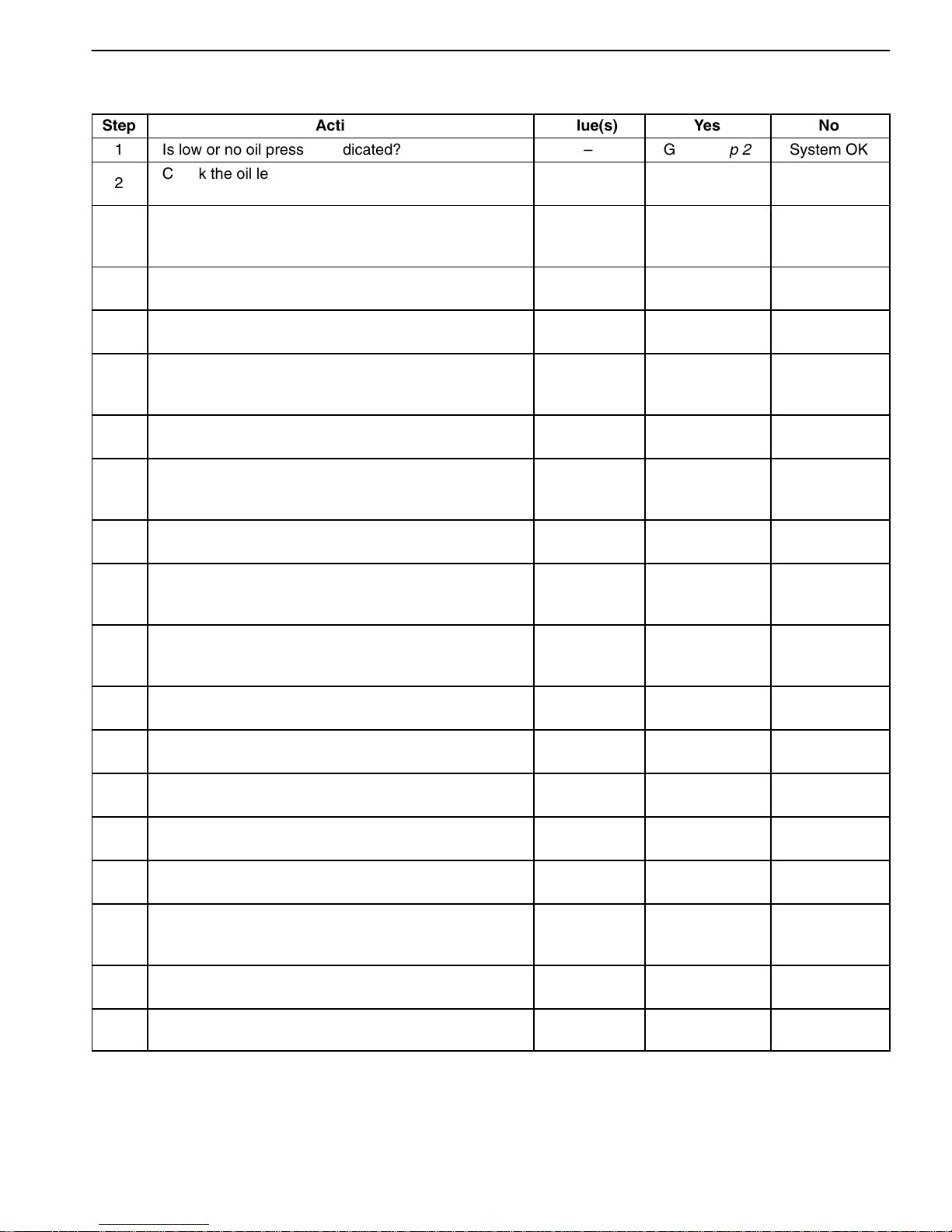
OIL PRESSURE TEST
Step
Action
Value(s)
Yes
No
1 Is low or no oil pressure indicated? – Go to Step 2 System OK
2
Check the oil level in the crankcase.
Is the level low?
– Go to Step 3 Go to Step 4
Add oil so that the oil level is up to the full mark on
3
4
5
the indicator.
Is the repair complete?
–
–
Go to Step 1
Check the idle speed.
Is the idle speed below the specified value? 825 rpm Go to Step 5 Go to Step 6
Increase the idle speed.
Is the speed increased?
– Go to Step 1 –
Inspect the oil pressure switch.
6
7
Is the oil pressure switch incorrect or
malfunctioning?
–
Go to Step 7 Go to Step 8
Install a new oil pressure switch.
Is the repair complete? – Go to Step 1 –
Inspect the oil pressure gauge.
8
9
Is the oil pressure gauge incorrect or
malfunctioning?
–
Go to Step 9 Go to Step 10
Install a new oil pressure gauge.
Is the repair complete? – Go to Step 1 –
Inspect the engine oil.
10
Is the engine oil in the crankcase diluted or of the
improper viscosity?
–
Go to Step 11 Go to Step 12
Install new engine oil of the proper viscosity for the
11
12
13
14
15
16
expected temperatures.
Is the repair complete?
–
Go to Step 1
Inspect the oil pump.
Is the pump worn or dirty?
– Go to Step 13 Go to Step 14
Replace the oil pump.
Is the repair complete? – Go to Step 1 –
Inspect the oil filter.
Is the oil filter plugged?
– Go to Step 15 Go to Step 16
Install a new oil filter.
Is the repair complete? – Go to Step 1 –
Inspect the oil pickup screen.
Is the oil pickup screen loose or plugged?
– Go to Step 17 Go to Step 18
–
Tighten or replace the oil pickup screen, as
17
18
19
necessary.
Is the repair complete?
–
–
Go to Step 1
Inspect the oil pickup tube.
Are there any holes in the oil pickup tube? – Go to Step 19 Go to Step 20
Replace the oil pickup tube.
Is the repair complete?
– Go to Step 1 –
DAEWOO T-154 BL2,3
Page 3
GENERAL ENGINE INFORMATION 1A – 3
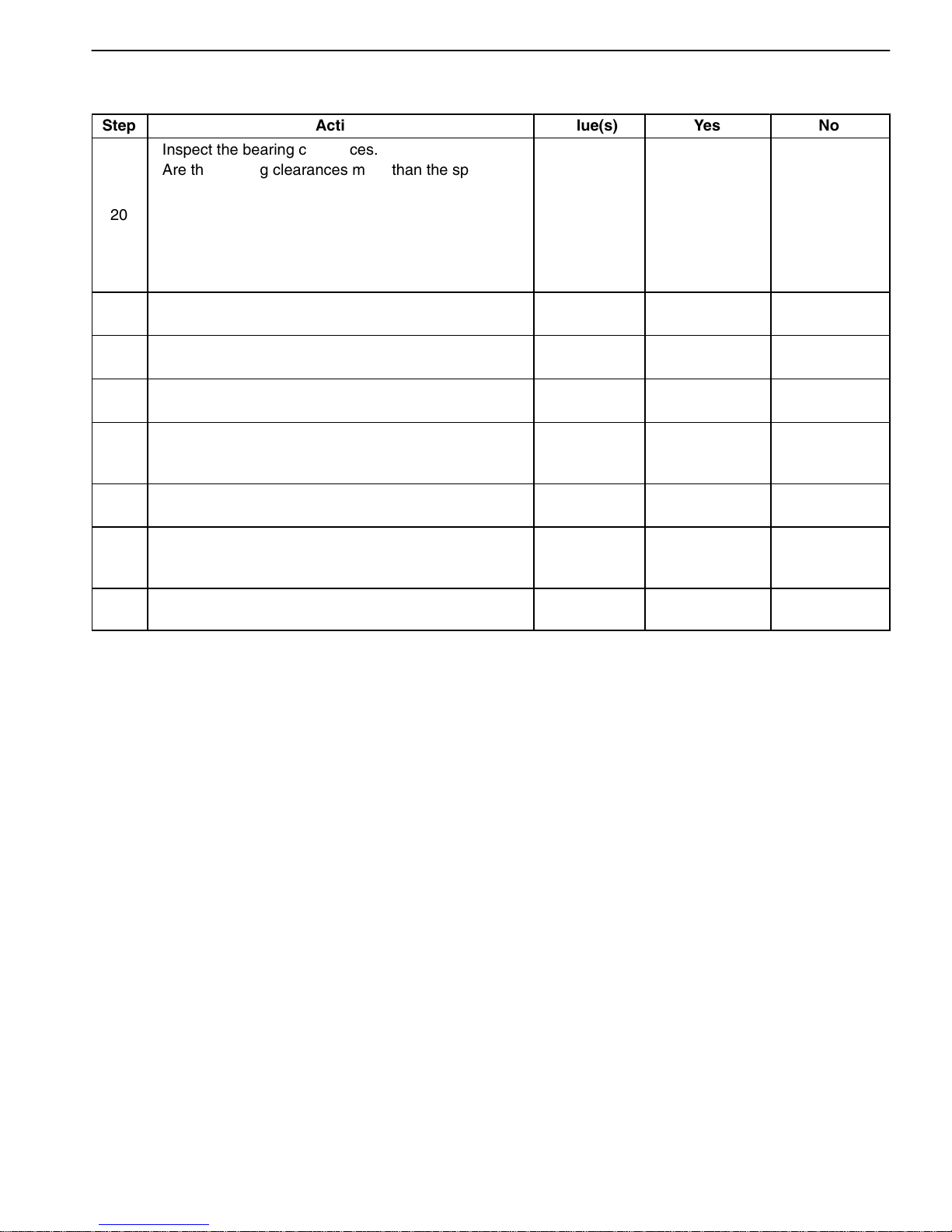
OIL PRESSURE TEST (CONT’D)
Step
20
21
22
23
24
25
26
27
Action
Inspect the bearing clearances.
Are the bearing clearances more than the specified
values?
Replace the bearing, if necessary.
Is the repair complete? – Go to Step 1 –
Inspect the oil galleries.
Are the oil galleries cracked, porous or plugged?
Repair or replace the engine block.
Is the repair complete? – Go to Step 1 –
Inspect the gallery plugs.
Are any of the gallery plugs missing or installed
improperly?
Install the plugs or repair them, as necessary.
Is the repair complete?
Inspect the camshaft.
Is the camshaft worn or is there evidence of poor
machining?
Replace the camshaft.
Is the repair complete? – Go to Step 1 –
Value(s)
Crankshaft
0.005 mm
(0.002 in.)
Connecting
Rod
0.019 X
0.070 mm
(0.0007 X
0.0027 in.)
– Go to Step 23 Go to Step 24
–
– Go to Step 1 –
–
Yes
Go to Step 21 Go to Step 22
Go to Step 25 Go to Step 26
Go to Step 27 System OK
No
OIL LEAK DIAGNOSIS
Most fluid oil leaks are easily located and repaired by
visually finding the leak and replacing or repairing the
necessary parts. On some occasions, a fluid leak may
be difficult to locate or repair. The following procedures
may help you in locating and repairing most leaks.
Finding the Leak:
1. Identify the fluid. Determine whether it is engine oil,
automatic transmission fluid, power steering fluid, etc.
2. Identify where the fluid is leaking from.
2.1. After running the vehicle at normal operating
temperature, park the vehicle over a large
sheet of paper.
2.2. Wait a few minutes.
2.3. Find the approximate location of the leak by
the drippings on the paper.
3. Visually check around the suspected component.
Check around all the gasket mating surfaces for
leaks. A mirror is useful for finding leaks in areas that
are hard to reach.
4. If the leak still cannot be found, it may be necessary to
clean the suspected area with a degreaser, steam, or
spray solvent.
4.1. Thoroughly clean the area.
4.2. Dry the area.
4.3. Operate the vehicle for several miles at normal
operating temperature and varying speeds.
4.4. After operating the vehicle, visually check the
suspected component.
4.5. If you still cannot locate the leak, try using the
powder or black light and dye method.
Powder Method:
1. Clean the suspected area.
2. Apply an aerosol-type powder, (such as foot powder),
to the suspected area.
3. Operate the vehicle under normal operating conditions.
4. Visually inspect the suspected component. Trace the
leak path over the white powder surface to the source.
Black Light and Dye Method:
A dye and light kit is available for finding leaks. Refer to
the manufacturer’s directions when using the kit.
1. Pour the specified amount of dye into the engine oil fill
tube.
2. Operate the vehicle under normal operating conditions as directed in the kit.
DAEWOO T-154 BL2,3
Page 4
1A – 4 GENERAL ENGINE INFORMATION
Ü
Ü
Ü
Ü
Ü
Ü
Ü
Ü
Ü
Ü
Ü
Ü
Ü
Ü
Ü
Ü
Ü
Ü
Ü
Ü
Ü
Ü
Ü
Ü
Ü
Ü
Ü
Ü
Ü
Ü
Ü
Ü
Ü
Ü
Ü
Ü
Ü
Ü
Ü
Ü
Ü
Ü
Ü
Ü
Ü
Ü
Ü
Ü
Ü
Ü
Ü
3. Direct the light toward the suspected area. The dyed
fluid will appear as a yellow path leading to the
source.
Repairing the Leak
Once the origin of the leak has been pinpointed and
traced back to its source, the cause of the leak must be
determined in order for it to be repaired properly. If a
gasket is replaced, but the sealing flange is bent, the
new gasket will not repair the leak. The bent flange must
be repaired also. Before attempting to repair a leak,
check for the following conditions and correct them as
they may cause a leak.
Gaskets:
D The fluid level/pressure is too high.
D The crankcase ventilation system is malfunctioning.
D The fasteners are improperly tightened or the threads
are dirty or damaged.
KNOCK DIAGNOSIS
Definition for Knock
Engine knock refers to various types of engine noise.
Heavy knock is usually very loud and the result of broken
or excessively worn internal engine components. Light
D The flanges or the sealing surface is warped.
D There are scratches, burrs or other damage to the
sealing surface.
D The gasket is damaged or worn.
D There is cracking or porosity of the component.
D An improper seal was used, (where applicable).
Seals:
D The fluid level/pressure is too high.
D The crankcase ventilation system is malfunctioning.
D The seal bore is damaged, scratched, burred or
nicked.
D The seal is damaged or worn.
D Improper installation is evident.
D There are cracks in the component.
D The shaft surface is scratched, nicked or damaged.
D A loose or worn bearing is causing excess seal wear.
knock is a noticeable noise, but not as loud. Light knock
can be caused by worn internal engine components.
Loose or broken external engine components can also
cause heavy or light knock.
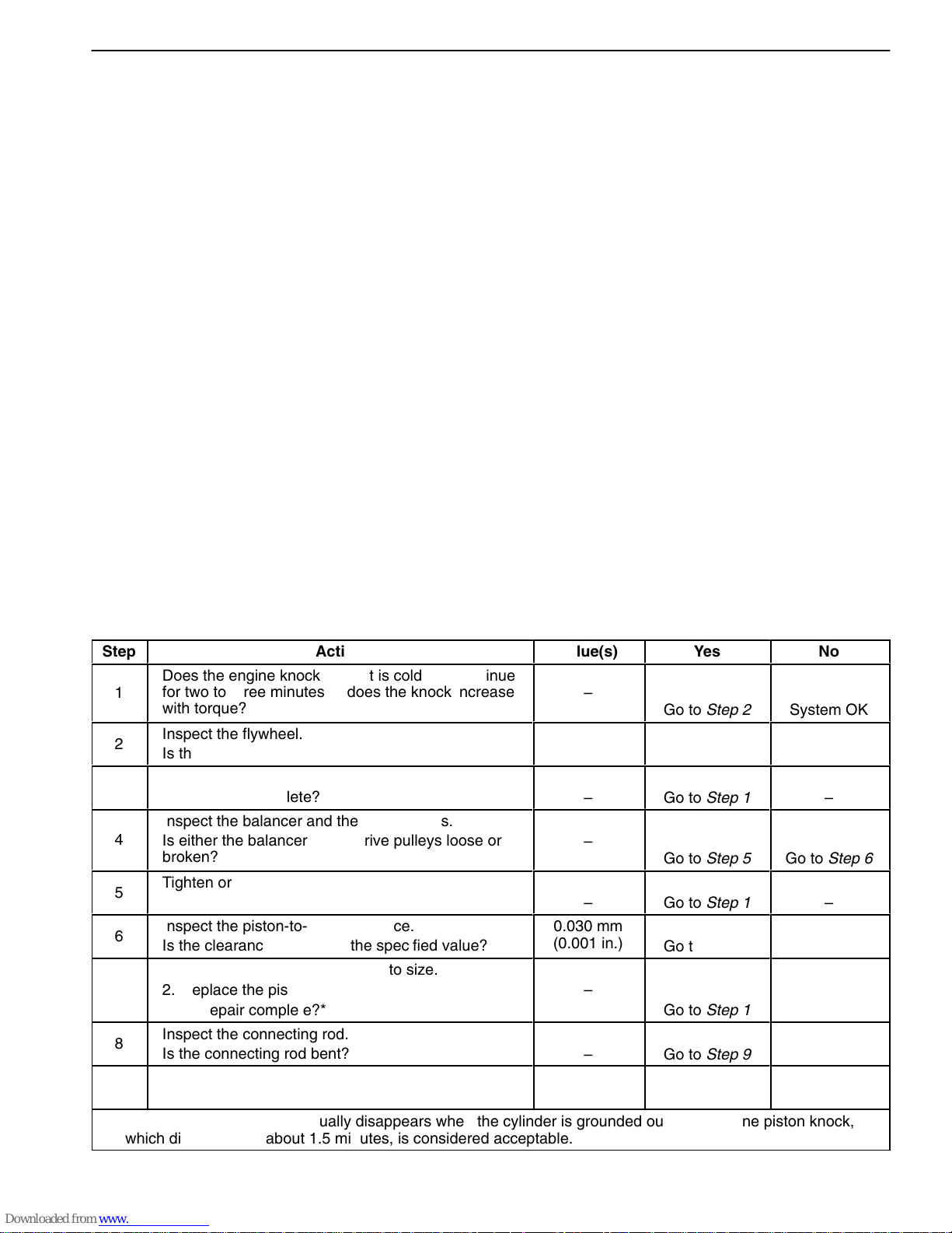
Engine Knocks Cold and Continues for Two-Three Minutes
and/or Knock Increases with Engine Torque
Step
ÜÜ
1
ÜÜ
2
ÜÜ
3
ÜÜ
4
ÜÜ
5
ÜÜ
6
ÜÜ
Does the engine knock when it is cold and continue
ЬЬЬЬЬЬЬЬЬЬЬЬЬЬЬ
for two to three minutes or does the knock increase
with torque?
ЬЬЬЬЬЬЬЬЬЬЬЬЬЬЬ
Inspect the flywheel.
Is the flywheel contacting the splash shield?
ЬЬЬЬЬЬЬЬЬЬЬЬЬЬЬ
Reposition the splash shield.
Is the repair complete?
Inspect the balancer and the drive pulleys.
ЬЬЬЬЬЬЬЬЬЬЬЬЬЬЬ
Is either the balancer or the drive pulleys loose or
ЬЬЬЬЬЬЬЬЬЬЬЬЬЬЬ
broken?
Tighten or replace the balancer or the drive pulleys.
Is the repair complete?
ЬЬЬЬЬЬЬЬЬЬЬЬЬЬЬ
Inspect the piston-to-bore clearance.
Is the clearance more than the specified value?
ЬЬЬЬЬЬЬЬЬЬЬЬЬЬЬ
1. Rebore the cylinder and hone to size.
7
ÜÜ
8
ÜÜ
9
ÜÜ
2. Replace the piston.
ЬЬЬЬЬЬЬЬЬЬЬЬЬЬЬ
Is the repair complete?*
Inspect the connecting rod.
ЬЬЬЬЬЬЬЬЬЬЬЬЬЬЬ
Is the connecting rod bent?
Replace the connecting rod.
ЬЬЬЬЬЬЬЬЬЬЬЬЬЬЬ
Is the repair complete?
* Cold engine piston knock usually disappears when the cylinder is grounded out. Cold engine piston knock,
which disappears in about 1.5 minutes, is considered acceptable.
ЬЬЬЬЬЬЬЬЬЬЬЬЬЬЬЬЬЬЬЬЬЬЬЬЬЬЬЬЬЬЬЬЬ
Action
Value(s)
ÜÜÜ
–
ÜÜÜ
–
ÜÜÜ
–
ÜÜÜ
–
ÜÜÜ
ÜÜÜ
–
0.030 mm
(0.001 in.)
ÜÜÜ
–
ÜÜÜ
ÜÜÜ
–
ÜÜÜ
–
Yes
ЬЬЬЬЬ
Go to Step 2
ЬЬЬЬЬ
Go to Step 3
ЬЬЬЬЬ
Go to Step 1
ЬЬЬЬЬ
ЬЬЬЬЬ
Go to Step 5
ЬЬЬЬЬ
Go to Step 1
Go to Step 7
ЬЬЬЬЬ
ЬЬЬЬЬ
Go to Step 1
ЬЬЬЬЬ
Go to Step 9
ЬЬЬЬЬ
Go to Step 1
No
ÜÜÜÜ
System OK
ÜÜÜÜ
Go to Step 4
ÜÜÜÜ
–
ÜÜÜÜ
ÜÜÜÜ
Go to Step 6
ÜÜÜÜ
–
Go to Step 8
ÜÜÜÜ
–
ÜÜÜÜ
ÜÜÜÜ
System OK
ÜÜÜÜ
–
DAEWOO T-154 BL2,3
Page 5
GENERAL ENGINE INFORMATION 1A – 5
Ü
Ü
Ü
Ü
Ü
Ü
Ü
Ü
Ü
Ü
Ü
Ü
Ü
Ü
Ü
Ü
Ü
Ü
Ü
Ü
Ü
Ü
Ü
Ü
Ü
Ü
Ü
Ü
Ü
Ü
Ü
Ü
Ü
Ü
Ü
Ü
Ü
Ü
Ü
Ü
Ü
Ü
Ü
Ü
Ü
Ü
Ü
Ü
Ü
Ü
Ü
Ü
Ü
Ü
Ü
Ü
Ü
Ü
Ü
Ü
Ü
Ü
Ü
Ü
Ü
Ü
Ü
Ü
Ü
Ü
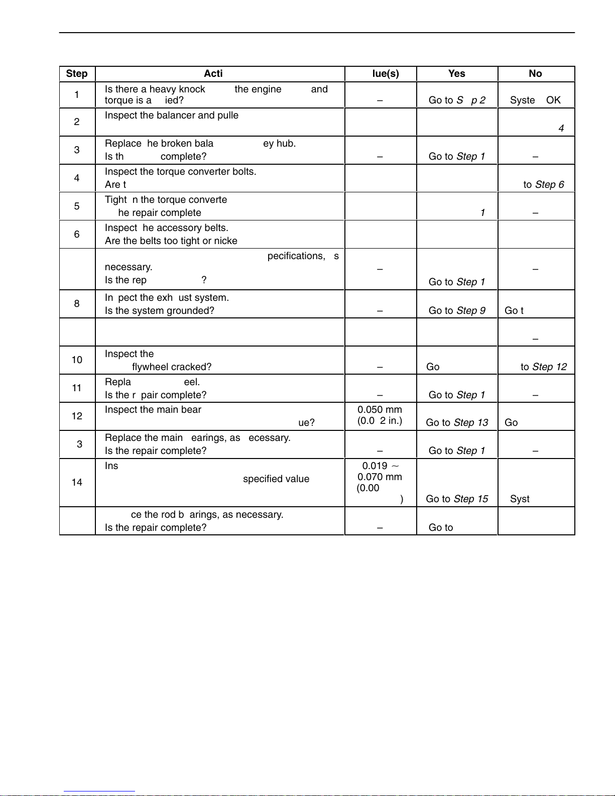
Heavy Knock Hot with Torque Applied
Step
1
ÜÜ
2
3
ÜÜ
4
ÜÜ
5
ÜÜ
6
ÜÜ
7
ÜÜ
8
ÜÜ
9
ÜÜ
10
ÜÜ
11
ÜÜ
12
ÜÜ
13
ÜÜ
14
ÜÜ
15
ÜÜ
Action
Is there a heavy knock when the engine is hot and
torque is applied?
Inspect the balancer and pulley hub.
ЬЬЬЬЬЬЬЬЬЬЬЬЬЬЬ
Is the balancer or pulley hub broken?
Replace the broken balancer or pulley hub.
ЬЬЬЬЬЬЬЬЬЬЬЬЬЬЬ
Is the repair complete?
Inspect the torque converter bolts.
ЬЬЬЬЬЬЬЬЬЬЬЬЬЬЬ
Are the bolts tightened to the specified value?
Tighten the torque converter bolts.
ЬЬЬЬЬЬЬЬЬЬЬЬЬЬЬ
Is the repair complete?
Inspect the accessory belts.
Are the belts too tight or nicked?
ЬЬЬЬЬЬЬЬЬЬЬЬЬЬЬ
Replace and/or tension the belts to specifications, as
necessary.
ЬЬЬЬЬЬЬЬЬЬЬЬЬЬЬ
Is the repair complete?
Inspect the exhaust system.
ЬЬЬЬЬЬЬЬЬЬЬЬЬЬЬ
Is the system grounded?
Reposition the system, as necessary.
ЬЬЬЬЬЬЬЬЬЬЬЬЬЬЬ
Is the repair complete?
Inspect the flywheel.
ЬЬЬЬЬЬЬЬЬЬЬЬЬЬЬ
Is the flywheel cracked?
Replace the flywheel.
Is the repair complete?
ЬЬЬЬЬЬЬЬЬЬЬЬЬЬЬ
Inspect the main bearing clearance.
Is the clearance more than the specified value?
Replace the main bearings, as necessary.
ЬЬЬЬЬЬЬЬЬЬЬЬЬЬЬ
Is the repair complete?
Inspect the rod bearing clearance.
ЬЬЬЬЬЬЬЬЬЬЬЬЬЬЬ
Is the clearance more than the specified value?
ЬЬЬЬЬЬЬЬЬЬЬЬЬЬЬ
Replace the rod bearings, as necessary.
ЬЬЬЬЬЬЬЬЬЬЬЬЬЬЬ
Is the repair complete?
Value(s)
–
ÜÜÜ
–
ÜÜÜ
–
45 NSm
ÜÜÜ
(33 lb-ft)
ÜÜÜ
–
–
ÜÜÜ
–
ÜÜÜ
ÜÜÜ
–
ÜÜÜ
–
ÜÜÜ
–
–
ÜÜÜ
0.050 mm
(0.002 in.)
ÜÜÜ
–
0.019 X
ÜÜÜ
0.070 mm
(0.0007 X
ÜÜÜ
0.0028 in.)
ÜÜÜ
–
Yes
Go to Step 2
ЬЬЬЬЬ
Go to Step 3
ЬЬЬЬЬ
Go to Step 1
ЬЬЬЬЬ
Go to Step 5
ЬЬЬЬЬ
Go to Step 1
Go to Step 7
ЬЬЬЬЬ
ЬЬЬЬЬ
Go to Step 1
ЬЬЬЬЬ
Go to Step 9
ЬЬЬЬЬ
Go to Step 1
ЬЬЬЬЬ
Go to Step 11
Go to Step 1
ЬЬЬЬЬ
Go to Step 13
ЬЬЬЬЬ
Go to Step 1
ЬЬЬЬЬ
ЬЬЬЬЬ
Go to Step 15
ЬЬЬЬЬ
Go to Step 1
No
System OK
ÜÜÜÜ
Go to Step 4
ÜÜÜÜ
–
ÜÜÜÜ
Go to Step 6
ÜÜÜÜ
–
Go to Step 8
ÜÜÜÜ
–
ÜÜÜÜ
ÜÜÜÜ
Go to Step 10
ÜÜÜÜ
–
ÜÜÜÜ
Go to Step 12
–
ÜÜÜÜ
Go to Step 14
ÜÜÜÜ
–
ÜÜÜÜ
ÜÜÜÜ
System OK
ÜÜÜÜ
–
DAEWOO T-154 BL2,3
Page 6
1A – 6 GENERAL ENGINE INFORMATION
Ü
Ü
Ü
Ü
Ü
Ü
Ü
Ü
Ü
Ü
Ü
Ü
Ü
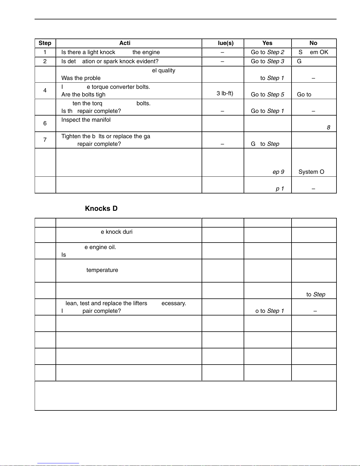
Light Knock Hot
Step
1
2
3
ÜÜ
4
ÜÜ
5
6
ÜÜ
7
ÜÜ
ÜÜ
8
ÜÜ
9
ÜÜ
Action
Is there a light knock when the engine is hot?
Is detonation or spark knock evident?
Value(s)
–
–
Yes
Go to Step 2
Go to Step 3
No
System OK
Go to Step 4
Check the engine timing and the fuel quality.
Was the problem found?
ЬЬЬЬЬЬЬЬЬЬЬЬЬЬЬ
Inspect the torque converter bolts.
Are the bolts tightened to the specified value?
–
ÜÜÜ
45 NSm
(33 lb-ft)
Go to Step 1
ЬЬЬЬЬ
ÜÜÜÜ
Go to Step 5 Go to Step 6
–
Tighten the torque converter bolts.
Is the repair complete?
– Go to Step 1 –
Inspect the manifold.
Is there an exhaust leak at the manifold? – Go to Step 7 Go to Step 8
Tighten the bolts or replace the gasket.
Is the repair complete? – Go to Step 1 –
Check the rod bearing clearance.
Is the clearance within the specified value?
0.019 X
0.070 mm
(0.0007 X
0.0028 in.) Go to Step 9 System OK
Replace the rod bearings as necessary.
Is the repair complete? – Go to Step 1 –
Knocks During Initial Start-Up But Last Only a Few Seconds
Step
1
2
Does the engine knock during initial start-up but last
only a few seconds?
Check the engine oil.
Is the proper viscosity oil used in the crankcase? – Go to Step 4 Go to Step 3
Action
Value(s)
Yes
– Go to Step 2 System OK
No
Install oil of the proper viscosity for the expected
3
seasonal temperatures.
Is the repair complete?
4
5
6
7
8
9
Inspect the hydraulic lifters.
Is there evidence of hydraulic lifter bleed-down? – Go to Step 5 Go to Step 6
Clean, test and replace the lifters, as necessary.
Is the repair complete?*
Inspect the crankshaft end clearance.
Is the clearance more than specified value?
Replace the crankshaft thrust bearing.
Is the repair complete? – Go to Step 1 –
Inspect the front main bearing clearance.
Is the clearance more than the specified value?
Replace the worn parts of the front main bearing.
Is the repair complete?
–
Go to Step 1
– Go to Step 1 –
0.1 mm
(0.0039 in.)
Go to Step 7 Go to Step 8
0.005 mm
(0.0001 in.)
Go to Step 9 System OK
– Go to Step 1 –
–
* When the engine is stopped, some valves will be open. Spring pressure against the lifters will tend to bleed
lifter down. Attempts to repair this should be made only if the problem is consistent.
ЬЬЬЬЬЬЬЬЬЬЬЬЬЬЬЬЬЬЬЬЬЬЬЬЬЬЬЬЬЬЬЬЬ
An engine that is only operated for short periods between start-ups may have lifter noise that lasts for a few
ЬЬЬЬЬЬЬЬЬЬЬЬЬЬЬЬЬЬЬЬЬЬЬЬЬЬЬЬЬЬЬЬЬ
minutes. This is a normal condition.
DAEWOO T-154 BL2,3
Page 7
GENERAL ENGINE INFORMATION 1A – 7
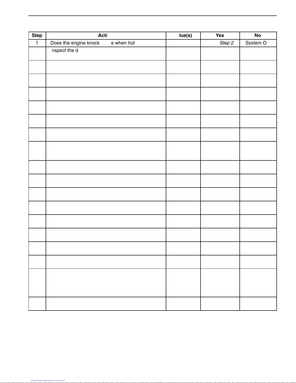
Knocks at Idle Hot
Step
Action
Value(s)
Yes
No
1 Does the engine knock at idle when hot? – Go to Step 2 System OK
2
3
4
5
6
7
8
Inspect the drive belts.
Are the belts loose or worn? – Go to Step 3 Go to Step 4
Tension or replace the belts, as necessary.
Is the repair complete?
– Go to Step 1 –
Inspect the A/C compressor and the generator.
Is either the compressor or the generator faulty? – Go to Step 5 Go to Step 6
Replace the faulty A/C compressor or the generator.
Is the repair complete?
– Go to Step 1 –
Inspect the valve train.
Are valve train components faulty? – Go to Step 7 Go to Step 8
Replace faulty valve train components.
Is the repair complete?
Check the engine oil.
Is the proper viscosity oil used in the crankcase?
– Go to Step 1 –
–
Go to Step 10 Go to Step 9
Install oil of the proper viscosity for the expected
9
10
11
12
13
14
15
16
17
18
seasonal temperatures.
Is the repair complete?
Inspect the piston pin clearance.
Is the clearance more than the specified value?
–
0.020 mm
(0.0008 in.)
Go to Step 1
Go to Step 11 Go to Step 12
Replace the piston and the pin.
Is the repair complete? – Go to Step 1 –
Check the connecting rod alignment.
Is the alignment faulty?
– Go to Step 13 Go to Step 14
Check and replace the rods, as necessary.
Is the repair complete? – Go to Step 1 –
Inspect the piston-to-bore clearance.
Is the clearance within the specified value?
0.030 mm
(0.0012 in.) Go to Step 16 Go to Step 15
Hone the bore and fit a new piston.
Is the repair complete?
– Go to Step 1 –
Inspect the crankshaft balancer.
Is the balancer loose?
– Go to Step 17 Go to Step 18
Torque or replace worn parts.
Is the repair complete? – Go to Step 1 –
Check the piston pin offset.
Is the offset at the specified value?
0.5 X 0.7
mm (0.020 X
0.028 in.)
–
Toward Thrust
Side Go to Step 19 System OK
19
Install the correct piston.
Is the repair complete? – Go to Step 1 –
DAEWOO T-154 BL2,3
Page 8
1A – 8 GENERAL ENGINE INFORMATION
NOISE DIAGNOSIS
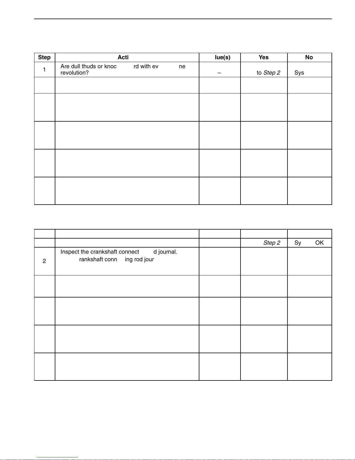
Main Bearing Noise
Step
1
2
3
4
5
6
Action
Are dull thuds or knocks heard with every engine
revolution? – Go to Step 2 System OK
Check the oil pump pressure.
Is the oil pump pressure low?
Inspect the crankshaft end play.
Does the crankshaft end play exceed the specified
value?
Inspect the crankshaft journals.
Are the crankshaft journals out-of-round?
Inspect the belt tension.
Does the belt tension exceed the specified value?
Inspect the crankshaft pulley.
Is the crankshaft pulley loose?
Value(s)
–
0.1 mm
(0.0039 in.)
0.004 mm
(0.0002 in.)
max.
–
–
Yes
Go to Oil
Pressure Test
Go to
Crankshaft
Replacement
Procedure
Go to
Crankshaft
Replacement
Procedure
Go to
Timing Belt
Replacement
Procedure Go to Step 6
Go to
Crankshaft
Replacement
Procedure
No
Go to Step 3
Go to Step 4
Go to Step 5
System OK
Connecting Rod Bearing Noise Symptom
Step
1 Is a knock noise heard under all engine speeds? – Go to Step 2 System OK
Inspect the crankshaft connecting rod journal.
2
3
4
5
6
Is the crankshaft connecting rod journal worn?
Check the oil pump pressure.
Is the oil pump pressure low?
Inspect the crankshaft connecting rod journals.
Are the journals out of round?
Inspect the connecting rods.
Is there a misaligned connecting rod?
Inspect the connecting rod bolts.
Are the connecting rod bolts torqued properly?
Action
Value(s)
–
–
–
–
–
Yes
Go to
Crankshaft
Replacement
Procedure Go to Step 3
Go to
Oil Pressure
Test Go to Step 4
Go to
Crankshaft
Replacement
Procedure Go to Step 5
Go to Pistons
and Rods
Replacement
Procedure Go to Step 6
System OK
No
Go to Pistons
and Rods
Replacement
Procedure
DAEWOO T-154 BL2,3
Page 9
GENERAL ENGINE INFORMATION 1A – 9
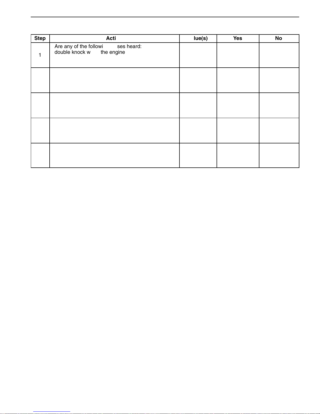
Piston Noises
Step
1
2
3
4
5
Action
Are any of the following noises heard: a sharp
double knock when the engine is idling, a light
ticking with no load on the engine or a ‘‘slapping’’
noise when the engine is cold?
Inspect the piston pin and the bushing.
Is the piston pin or the bushing worn or loose?
Inspect the piston.
Is the piston broken or cracked?
Inspect the connecting rods.
Is there a misaligned connecting rod?
Inspect the piston position.
Is the piston 180_ out of position?
Value(s)
–
–
–
–
–
Yes
No
Go to Step 2 System OK
Go to Pistons
and Rods
Replacement
Procedure Go to Step 3
Go to Pistons
and Rods
Replacement
Procedure Go to Step 4
Go to Pistons
and Rods
Replacement
Procedure Go to Step 5
Go to Pistons
and Rods
Replacement
Procedure System OK
DAEWOO T-154 BL2,3
Page 10
1A – 10 GENERAL ENGINE INFORMATION
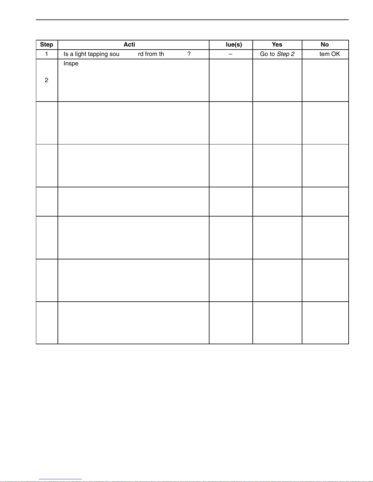
Valve Mechanism or Valve Train Noises
Step
Action
Value(s)
Yes
No
1 Is a light tapping sound heard from the engine? – Go to Step 2 System OK
Inspect the valve springs.
Are the springs weak or broken?
2
–
Go to
Cylinder Head
and Valve Train
Components
Replacement
Procedure Go to Step 3
Inspect the valves.
Are the valves sticking or warped?
3
–
Go to
Cylinder Head
and Valve Train
Components
Replacement
Procedure
Inspect the valve lifters.
Are the valve lifters dirty, stuck or worn?
4
–
Go to
Cylinder Head
and Valve Train
Components
Go to Step 4
Replacement
Procedure Go to Step 5
Inspect the camshaft lobes.
5
Are the camshaft lobes damaged or improperly
machined?
–
Check the oil supply to the valve train.
Is the oil supply insufficient or poor?
6
–
Go to
Camshaft
Replacement
Procedure Go to Step 6
Go to
Cylinder Head
and Valve Train
Components
Replacement
Procedure Go to Step 7
Inspect the valve guides.
Are the valve guides worn?
7
–
Go to
Cylinder Head
and Valve Train
Components
Replacement
Procedure
Inspect the valve spring seat.
Is the valve spring seat incorrect?
8
–
Go to
Cylinder Head
and Valve Train
Components
Go to Step 8
Replacement
Procedure System OK
DAEWOO T-154 BL2,3
Page 11

GENERAL ENGINE INFORMATION 1A – 11
GENERAL INFORMATION
CLEANLINESS AND CARE
An automobile engine is a combination of many machined, honed, polished and lapped surfaces with tolerances that are measured in the ten-thousandths of
an inch. When any internal engine parts are serviced,
care and cleanliness are important. A liberal coating of
engine oil should be applied to friction areas during assembly, to protect and lubricate the surfaces on initial
operation. Proper cleaning and protection of machined
surfaces and friction areas is part of the repair procedure. This is considered standard shop practice even if
not specifically stated.
Whenever valve train components are removed for service, they should be kept in order. They should be
installed in the same locations, and with the same mating
surfaces, as when they were removed.
Battery cables should be disconnected before any major
work is performed on the engine. Failure to disconnect
cables may result in damage to wire harness or other
electrical parts.
ON-ENGINE SERVICE
Caution: Disconnect the negative battery cable before removing or installing any electrical unit, or
when a tool or equipment could easily come in contact with exposed electrical terminals. Disconnecting this cable will help prevent personal injury and
damage to the vehicle. The ignition must also be in
LOCK unless otherwise noted.
Notice: Any time the air cleaner is removed, the intake
opening should be covered. This will protect against accidental entrance of foreign material, which could follow
the intake passage into the cylinder and cause extensive
damage when the engine is started.
DAEWOO T-154 BL2,3
Page 12

BLANK
DAEWOO T-154 BL2,3
Page 13

.
SECTION 1B
SOHC ENGINE MECHANI CAL
CAUTION: Disconnect the negative battery cable before removing or installing any electrical unit or when a
tool or equipment could easily come in contact with exposed electrical terminals. Disconnecting this cable
will help prevent personal injury and damage to the vehicle. The ignition must also be in LOCK unless
otherwise noted.
TABLE OF CONTENTS
Specifications 1B-2. . . . . . . . . . . . . . . . . . . . . . . . . . . . .
Engine Specifications 1B-2. . . . . . . . . . . . . . . . . . . . . .
Fastener Tightening Specifications 1B-4. . . . . . . . . . .
Special Tools 1B-5. . . . . . . . . . . . . . . . . . . . . . . . . . . . . .
Special Tools Table 1B-5. . . . . . . . . . . . . . . . . . . . . . . .
Component Locator 1B-8. . . . . . . . . . . . . . . . . . . . . . . .
Upper End 1B-8. . . . . . . . . . . . . . . . . . . . . . . . . . . . . . . .
Lower End 1B-10. . . . . . . . . . . . . . . . . . . . . . . . . . . . . . .
Maintenance and Repair 1B-12. . . . . . . . . . . . . . . . . . .
On-Vehicle Service 1B-12. . . . . . . . . . . . . . . . . . . . . . . . .
Valve Cover 1B-12. . . . . . . . . . . . . . . . . . . . . . . . . . . . .
Cylinder Head and Gasket 1B-13. . . . . . . . . . . . . . . . .
Camshaft 1B-27. . . . . . . . . . . . . . . . . . . . . . . . . . . . . . .
Timing Belt Check and Adjust 1B-31. . . . . . . . . . . . . .
Timing Belt 1B-36. . . . . . . . . . . . . . . . . . . . . . . . . . . . . .
Oil Pump 1B-42. . . . . . . . . . . . . . . . . . . . . . . . . . . . . . . .
Oil Pan 1B-47. . . . . . . . . . . . . . . . . . . . . . . . . . . . . . . . .
Engine Mount 1B-50. . . . . . . . . . . . . . . . . . . . . . . . . . . .
Intake Manifold 1B-52. . . . . . . . . . . . . . . . . . . . . . . . . . .
Exhaust Manifold 1B-57. . . . . . . . . . . . . . . . . . . . . . . . .
Camshaft Gear 1B-58. . . . . . . . . . . . . . . . . . . . . . . . . .
Rear Timing Belt Cover 1B-60. . . . . . . . . . . . . . . . . . .
Engine 1B-61. . . . . . . . . . . . . . . . . . . . . . . . . . . . . . . . . .
Pistons and Rods 1B-71. . . . . . . . . . . . . . . . . . . . . . . .
Unit Repair 1B-77. . . . . . . . . . . . . . . . . . . . . . . . . . . . . . . .
Cylinder Head and Valve Train
Components 1B-77. . . . . . . . . . . . . . . . . . . . . . . . . . .
Crankshaft 1B-85. . . . . . . . . . . . . . . . . . . . . . . . . . . . . .
Crankshaft Bearings and Connecting Rod
Bearings – Gauging Plastic 1B-93. . . . . . . . . . . . . .
General Description and System
Operation 1B-96. . . . . . . . . . . . . . . . . . . . . . . . . . . . . . .
Cylinder Head and Gasket 1B-96. . . . . . . . . . . . . . . . .
Crankshaft 1B-96. . . . . . . . . . . . . . . . . . . . . . . . . . . . . .
Timing Belt 1B-96. . . . . . . . . . . . . . . . . . . . . . . . . . . . . .
Oil Pump 1B-96. . . . . . . . . . . . . . . . . . . . . . . . . . . . . . . .
Oil Pan 1B-96. . . . . . . . . . . . . . . . . . . . . . . . . . . . . . . . .
Exhaust Manifold 1B-96. . . . . . . . . . . . . . . . . . . . . . . . .
Intake Manifold 1B-96. . . . . . . . . . . . . . . . . . . . . . . . . . .
Camshaft 1B-96. . . . . . . . . . . . . . . . . . . . . . . . . . . . . . .
Exhaust Gas Recirculation Valve 1B-96. . . . . . . . . . .
DAEWOO T-154 BL2,3
Page 14

1B–2 SOHC ENGINE MECHANICAL
SPECIFICATIONS
ENGINE SPECIFICATIONS
Application Description (Manual and Automatic)
General Data:
Engine Type 4 Cylinder (In-Line)
Displacement:
1.5 SOHC 1 498 cm3 (91.44 in3)
Bore Stroke:
1.5 SOHC 76.5 X 81.5 mm (3.01 in. X 3.21 in.)
Compression Ratio 9.5 0.2:1
Firing Order 1–3–4–2
Cylinder Bore:
Diameter 76.5 mm (3.01 in.)
Out of Round (Maximum) 0.0065 mm (0.00025 in.)
Taper (Maximum):
1.5 SOHC 0.0065 mm (0.00025 in.)
Piston:
Diameter 76.470 mm (3.01 in.)
Clearance to Bore 0.030 mm (0.0012 in.)
Piston Rings:
Ring, End Gap:Ring, End Gap:
Top Compression 0.3 mm (0.019 in.)
2nd Compression 0.3 mm (0.019 in.)
Groove Clearance:Groove Clearance:
Top Impression 0.02 mm (0.0008 in)
2nd Impression 0.02 mm (0.0008 in.)
Piston Pin:
Diameter 18.000 mm (0.708 in.)
Pin Off-Set 0.5 0.7 mm (0.019 0.027 in.)
Camshaft:
Lift Intake:
1.5 SOHC 6.12 mm (0.240 in.)
Lift Exhaust 6.12 mm (0.240 in.)
End Play 0.09 0.21 mm (0.0035 0.0082 in.)
Journal OD:Journal OD:
No. 1 39.445 mm (1.552 in.)
No. 2 39.700 mm (1.562 in.)
No. 3 39.945 mm (1.572 in.)
No. 4 40.200 mm (1.582 in.)
No. 5 40.445 mm (1.592 in.)
DAEWOO T-154 BL2,3
Page 15
SOHC ENGINE MECHANICAL 1B–3
Á
Á
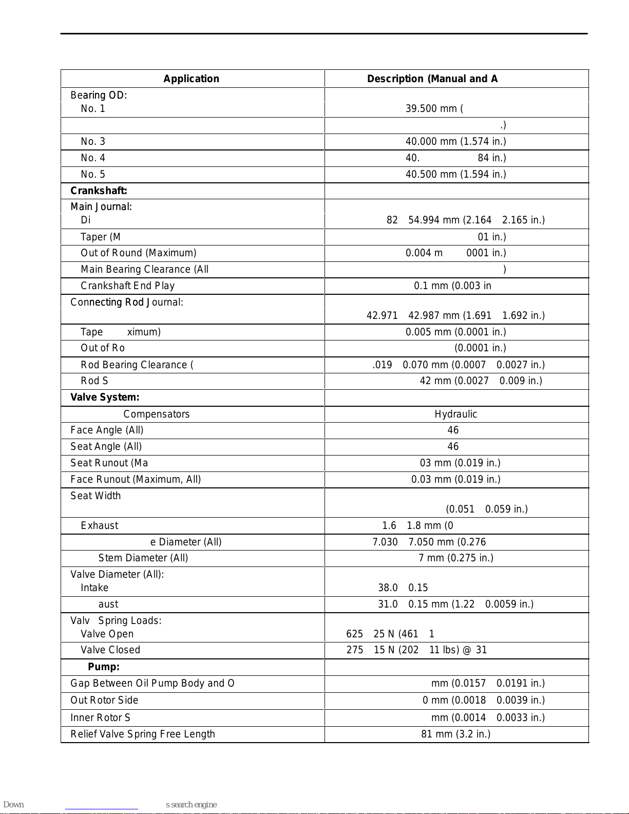
ENGINE SPECIFICATIONS (Cont’d)
Application
Bearing OD:
Bearing OD:
No. 1
No. 2
No. 3
No. 4
No. 5
Crankshaft:
Main Journal:
Main Journal:
Diameter (All)
Taper (Maximum)
Out of Round (Maximum)
Main Bearing Clearance (All)
Crankshaft End Play
Connecting Rod Journal:
Connecting Rod Journal:
Diameter (All)
Taper (Maximum)
Out of Round (Maximum)
Rod Bearing Clearance (All)
Rod Side Clearance
Valve System:
Valve Lash Compensators
Face Angle (All)
Seat Angle (All)
Seat Runout (Maximum, All)
Face Runout (Maximum, All)
Seat Width:
Seat Width:
Intake
Exhaust
Valve Guide Inside Diameter (All)
Valve Stem Diameter (All)
Valve Diameter (All):
Valve Diameter (All):
Intake
Exhaust
Valve Spring Loads:
Valve Spring Loads:
Valve Open
Valve Closed
Oil Pump:
Gap Between Oil Pump Body and Out Rotor
Out Rotor Side Clearance
Inner Rotor Side Clearance
ББББББББББББББББ
Relief Valve Spring Free Length
Description (Manual and Automatic)
39.500 mm (1.555 in.)
39.750 mm (1.564 in.)
40.000 mm (1.574 in.)
40.250 mm (1.584 in.)
40.500 mm (1.594 in.)
54.982 54.994 mm (2.164 2.165 in.)
0.005 mm (0.0001 in.)
0.004 mm (0.0001 in.)
0.005 mm (0.0001 in.)
0.1 mm (0.003 in.)
42.971 42.987 mm (1.691 1.692 in.)
0.005 mm (0.0001 in.)
0.004 mm (0.0001 in.)
0.019 0.070 mm (0.0007 0.0027 in.)
0.070 0.242 mm (0.0027 0.009 in.)
Hydraulic
46
46
0.03 mm (0.019 in.)
0.03 mm (0.019 in.)
1.3 1.5 mm (0.051 0.059 in.)
1.6 1.8 mm (0.063 0.071 in. )
7.030 7.050 mm (0.276 0.277 in.)
7 mm (0.275 in.)
38.0 0.15 mm (1.49 0.0059 in.)
31.0 0.15 mm (1.22 0.0059 in.)
625 25 N (461 18 lbs) @ 21.5 mm (0.846 in.)
275 15 N (202 11 lbs) @ 31.5 mm (1.240 in.)
0.400 0.484 mm (0.0157 0.0191 in.)
0.045 0.100 mm (0.0018 0.0039 in.)
ББББББББББББББББ
0.035 0.085 mm (0.0014 0.0033 in.)
81 mm (3.2 in.)
DAEWOO T-154 BL2,3
Page 16

1B–4 SOHC ENGINE MECHANICAL
FASTENER TIGHTENING SPECIFICATIONS
Application Nm Lb-Ft Lb-In
A/C Compressor Hose Assembly Retaining Bolt 33 24 –
A/C Compressor Mounting Bolts 27 20 –
A/C Compressor Mounting Bracket Bolts 50 37 –
Air Filter Housing Bolts 8 – 71
Alternator Adjusting Bolt 25 18 –
Alternator Adjusting Bracket Retaining Bolt 25 18 –
Auxiliary Catalytic Converter-to-Exhaust Manifold Nuts
and Bracket Bolts
Camshaft Gear Bolt 45 33 –
Camshaft Pressure Plate Bolts 10 – 89
Connecting Rod Bearing Cap Bolts 25 + 30 18 + 30 –
Coolant Pump Retaining Bolts 10 – 89
Coolant Temperature Sensor 20 15 –
Crankshaft Bearing Cap Bolts 50
Crankshaft Pulley Bolt 95
Crankshaft Position Sensor Retaining Bolt 10 – 89
Cylinder Head Bolts (Camshaft Support Housing &
Cylinder Head Mounting Bolts)
Electronic Ignition System Ignition Coil Mounting Bolts 10 – 89
Electronic Ignition System Ignition Coil Mounting Plate
Bolts 10
Engine Lift Bracket Bolt 25 18 –
Engine Mount Attaching Nuts 40 30 –
Engine Mount Bracket Retaining Bolts 60 44 –
Engine Mount Bracket-to-Engine Mount Retaining Bolts 60 44 –
Exhaust Manifold Heat Shield Bolts 15 11 –
Exhaust Manifold Nuts 25 18 –
Flexible Plate Bolts 60 44 –
Flexible Plate Inspection Cover Bolts 10 – 89
Flywheel Bolts 35
Flywheel Inspection Cover Bolts 12 – 106
Front Muffler-to-Main Catalytic Converter Nuts 30 22 –
Fuel Rail Retaining Bolts 25 18 –
Intake Manifold Retaining Nuts 25 18 –
40 30 –
37
+ 45 + 15
+ 45 + 15 –
70
+ 30 + 15
25 + 70
+ 70 + 30
+ 30 + 15 –
18 + 70
+ 70 + 30
–
26
+ 30 + 15
+ 30 + 15 –
–
89
DAEWOO T-154 BL2,3
Page 17
SOHC ENGINE MECHANICAL 1B–5
FASTENER TIGHTENING SPECIFICATIONS (Con t ’d)
Application Nm Lb-Ft Lb-In
Intake Manifold Support Bracket Retaining Bolts 22 16 –
Lower Timing Belt Cover Bolts 10 – 89
Oil Pan Retaining Bolts 10 – 89
Oil Pan Drain Plug 55 41 –
Oil Pressure Switch 40 30 –
Oil Pump Retaining Bolts 10 – 89
Oil Pump/Pickup Tube and Support Bracket Bolts 10 – 89
Oil Pump Safety Relief Valve Bolt 30 22 –
Oil Pump Rear Cover Bolts 6 – 53
Power Steering Pump Mounting Bolts 25 18 –
Power Steering Pump Pulley Bolts 25 18 –
Rear Timing Belt Cover Bolts 10 – 89
Right Transaxle Brace Bolts 60 44 –
Spark Plugs 25 18 –
Thermostat Housing Mounting Bolts 20 15 –
Throttle Cable Bracket Bolts 8 – 71
Timing Belt Automatic Tensioner Bolt 20 15 –
Transaxle Bell Housing Bolts 75 55 –
Transaxle Torque Converter Bolts 65 48 –
Upper Timing Belt Cover Bolts 10 – 89
Valve Cover Bolts 9 – 80
A102B150
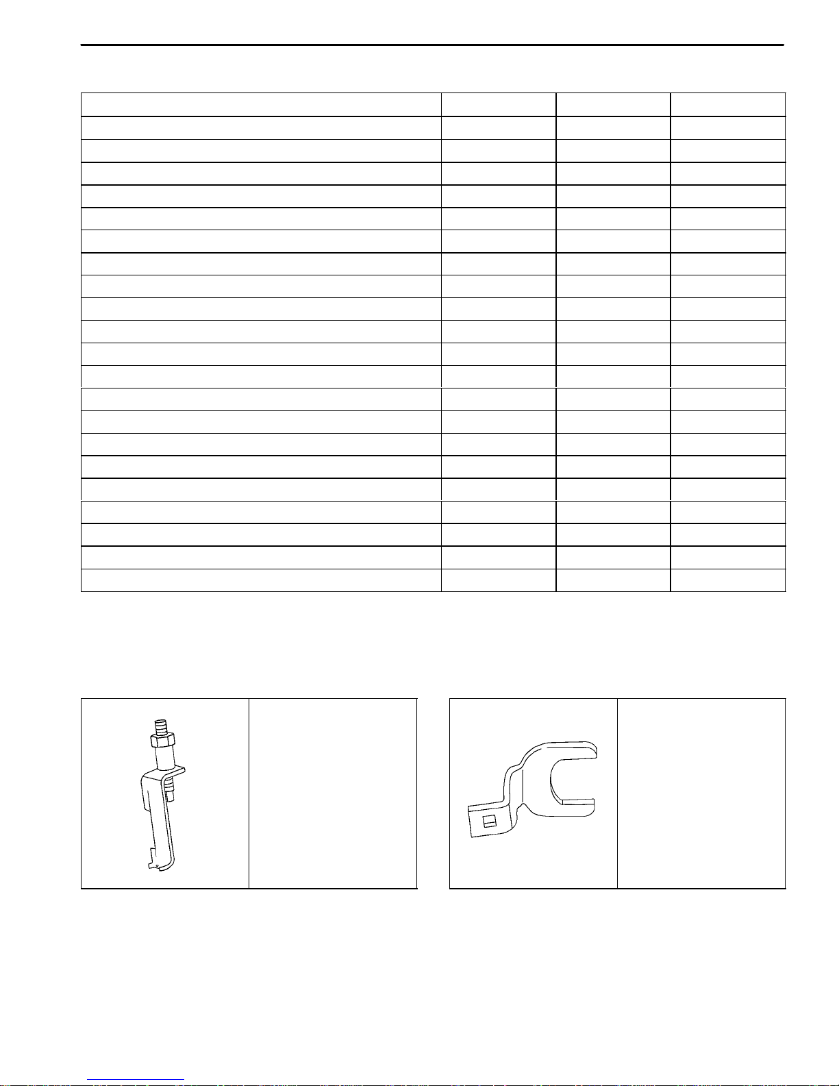
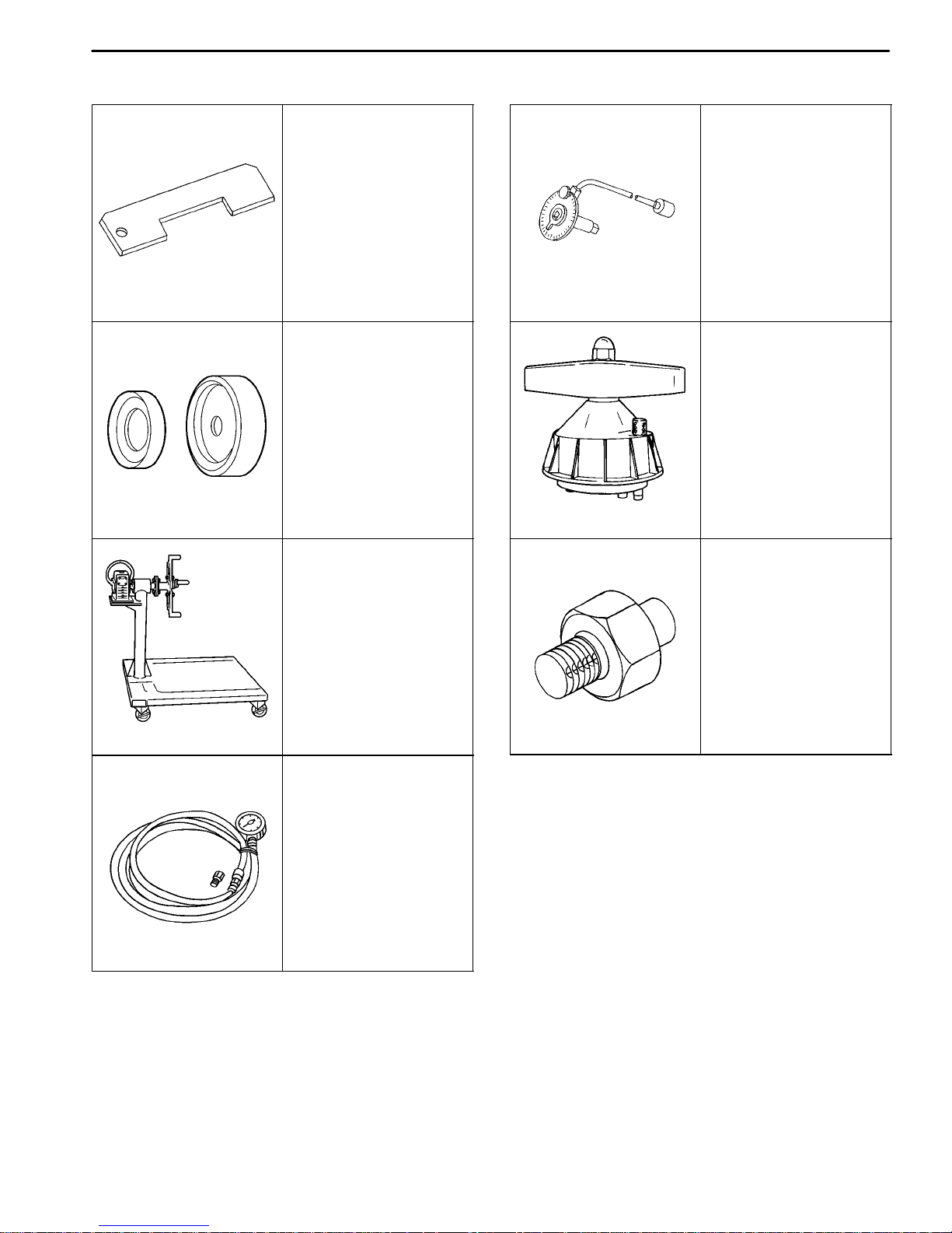
SPECIAL TOOLS
SPECIAL TOOL S TABLE
KM-565-A
Valve Spring
Compressor
J-42492
Timing Belt Adjuster
A102B151
DAEWOO T-154 BL2,3
Page 18
1B–6 SOHC ENGINE MECHANICAL
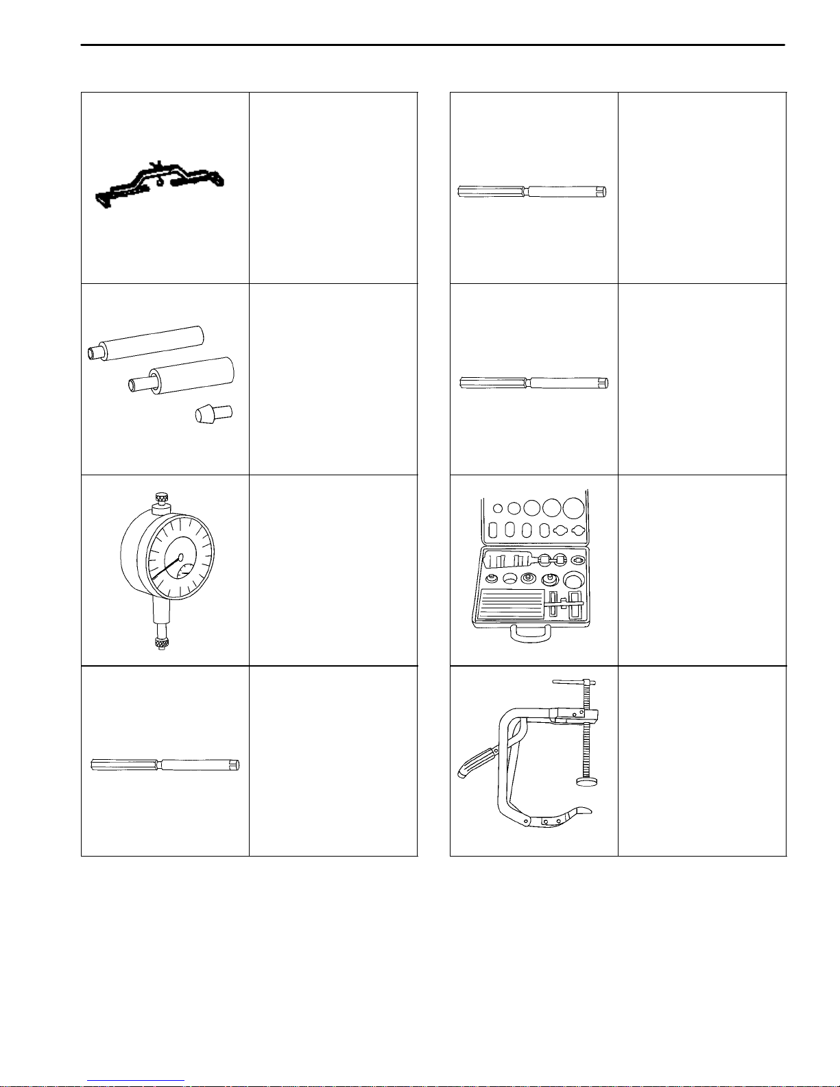
SPECIAL TOOLS TABLE (Cont’d)
A102B152
A102B153
KM -263-B
Engine Assembly
Support Fixture
KM-427
Piston Pin Service Set
MKM-571-B
Gauge
KM-254
Valve Guide Reamer
A102B155
KM-255
Valve Guide Reamer
A102B155
KM-340-0
Cutter Set
Includes: KM-340-7
Includes: KM-340-13
Includes: KM-340-26
A102B154
A102B155
KM-253
Valve Guide Reamer
A102B156
KM-348
Valve Spring
Compressor
A102B157
DAEWOO T-154 BL2,3
Page 19
SOHC ENGINE MECHANICAL 1B–7
SPECIAL TOOLS TABLE (Cont’d)
A102B158
A102B160
KM-419
Distance Gauge
KM-635
Crankshaft Rear Oil
Seal Installer
MKM-412
Engine Overhaul Stand
KM-470-B
Angular Torque Gauge
A102B161
J-36972
Crankshaft Rear Oil
Seal Installer
A102C155
KM-135
Adapter
A102B159
A202B005
B102C044
KM-498-B
Pressure Gauge
DAEWOO T-154 BL2,3
Page 20
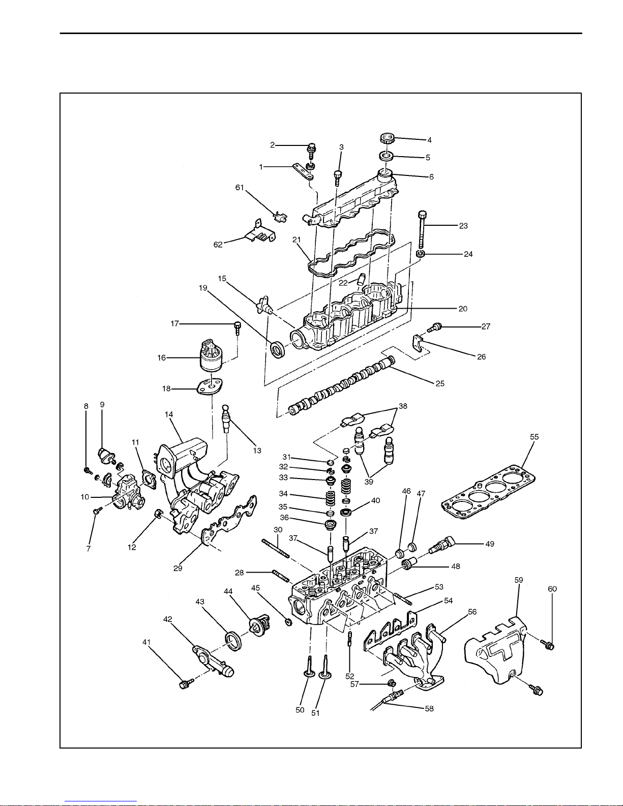
1B–8 SOHC ENGINE MECHANICAL
COMPONENT LOCATOR
UPPER END
A402B001
DAEWOO T-154 BL2,3
Page 21

SOHC ENGINE MECHANICAL 1B–9
1 Wiring Bracket
2 Bolt
3 Bolt
4 Cap, Bayonet Joint
5 Seal, Bayonet Cap
6 Valve Cover
7 Bolt
8 Throttle Position Sensor
9 Idle Air Control Valve
10 Throttle Body
11 Throttle Body Gasket
12 Nut
13 Engine Coolant Temperature Sensor
14 Intake Manifold
15 Camshaft Position Sensor
16 EGR Valve
17 Bolt
18 EGR Gasket
19 Shaft Seal Ring
20 Camshaft Support
21 Valve Cover Gasket
22 Tube
23 Cylinder Head Bolt
24 Washer
25 Camshaft
26 Camshaft Pressure Plate
27 Bolt
28 Bolt-Stud
29 Intake Manifold Gasket
30 Bolt-Stud
31 Valve Thrust Piece
32 Valve Key
33 Valve Spring Plate
34 Valve Spring
35 Valve Stem Seal
36 Exhaust Valve Spring Seat
37 Valve Guide
38 Cam Follower
39 Cam Follower Lifter
40 Intake Valve Spring Seat
41 Bolt
42 Thermostat Housing
43 Thermostat Housing Seal Ring
44 Thermostat
45 Screw Plug
46 Oil Duct Cap
47 Oil Duct Cap
48 Adapter
49 Coolant Temperature Sensor
50 Exhaust Valve
51 Intake Valve
52 Cylinder Head Oil Duct Sleeve
53 Bolt-Stud
54 Exhaust Manifold Gasket
55 Cylinder Head Gasket
56 Exhaust Manifold
57 Nut
58 Exhaust Oxygen Sensor
59 Exhaust Manifold Heat Shield
60 Bolt
61 EGR Solenoid
62 Bracket
DAEWOO T-154 BL2,3
Page 22
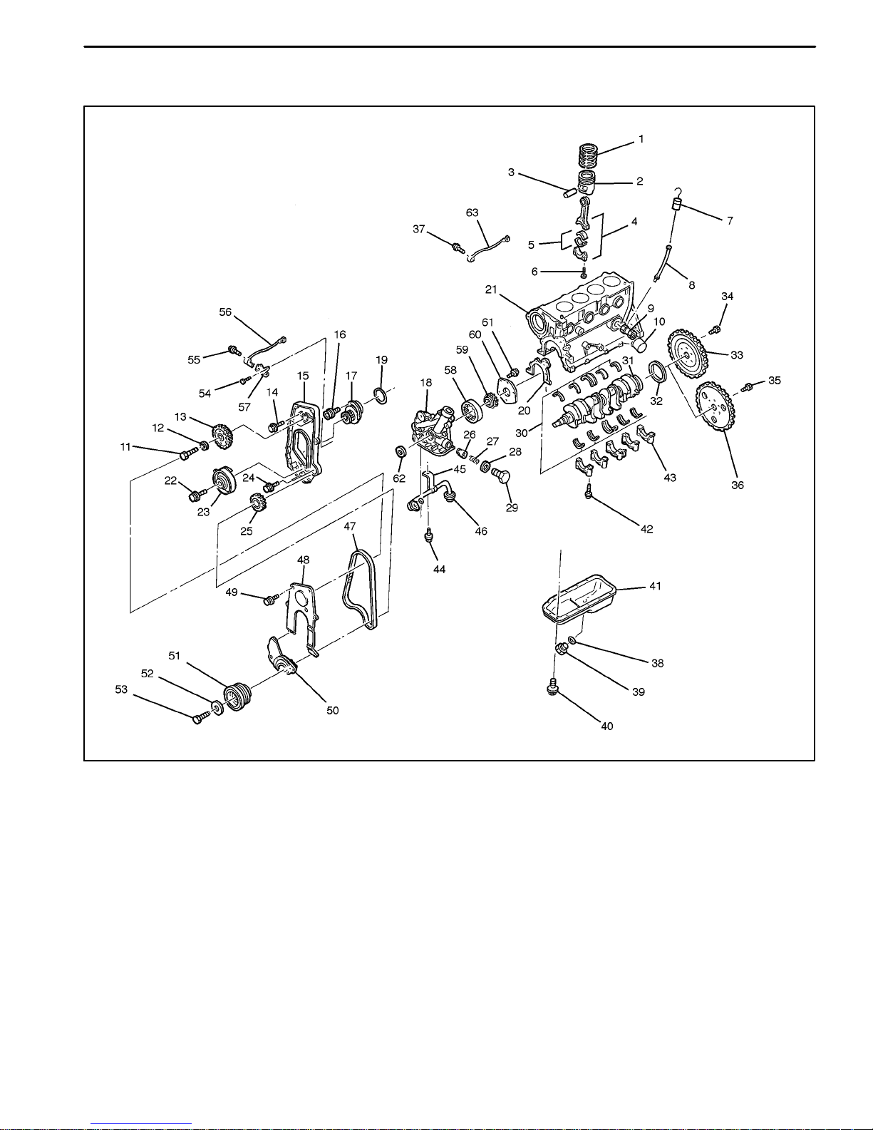
1B–10 SOHC ENGINE MECHANICAL
LOWER END
A202B006
DAEWOO T-154 BL2,3
Page 23

SOHC ENGINE MECHANICAL 1B–11
1 Piston Ring Seat
2 Piston
3 Piston Pin
4 Connecting Rod
5 Connecting Rod Bearing Set
6 Connecting Rod Bolt
7 Oil Level Gauge Stick
8 Gauge Stick Tube
9 Connecting Piece
10 Oil Filter
11 Camshaft Pulley Bolt
12 Washer
13 Camshaft Gear
14 Rear Cover Bolt
15 Rear Timing Belt Cover
16 Bolt
17 Coolant Pump
18 Oil Pump
19 Seal Ring
20 Oil Pump Body Gasket
21 Engine Block
22 Bolt
23 Auto Tensioner
24 Bolt
25 Crankshaft Gear
26 Pressure Relief Valve Plunger
27 Spring
28 Oil Pump Seal Ring
29 Bolt Plug
30 Crankshaft Bearing Set
31 Crankshaft
32 Shaft Seal Ring
33 Flywheel (Manual Transaxle)
34 Bolt (Manual Transaxle)
35 Bolt (Automatic Transaxle)
36 Flex Plate (Automatic Transaxle)
37 Bolt
38 Threaded Ring
39 Drain Plug
40 Bolt
41 Oil Pan
42 Main Bearing Cap Bolt
43 Main Bearing
44 Bolt
45 Bracket
46 Oil Pickup Tube
47 Timing Belt
48 Upper Timing Belt Front Cover
49 Bolt
50 Lower Timing Belt Front Cover
51 Crankshaft Pulley
52 Washer
53 Bolt
54 Bolt
55 Bolt
56 Crankshaft Position Sensor
57 Bracket
58 Gear
59 Gear
60 Cover
61 Bolt
62 Seal
63 Knock Sensor
DAEWOO T-154 BL2,3
Page 24
1B–12 SOHC ENGINE MECHANICAL
MAINTENANCE AND REPAIR
ON-VEHICLE SERVICE
VALVE COVER
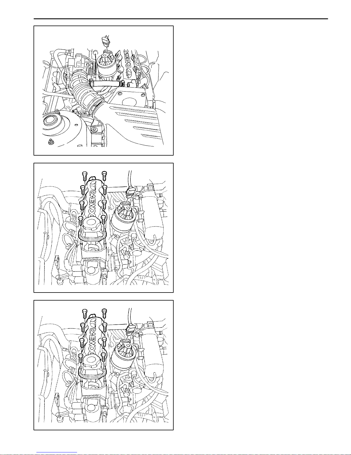
Removal Procedure
1. Disconnect the negative battery cable.
2. Disconnect the breather tube from the valve cover.
A402B002
3. Remove the eight bolts from the valve cover.
4. Remove the valve cover.
5. Remove the valve cover gasket.
6. Clean the sealing surfaces of the valve cover and the
camshaft housing.
A402B003
Installation Procedure
1. Install the new valve cover gasket and the valve cover.
2. Install the eight bolts to the valve cover.
Tighten
Tighten the valve cover bolts to 9 N m (80 lb-in).
A402B003
DAEWOO T-154 BL2,3
Page 25
A402B002
d
SOHC ENGINE MECHANICAL 1B–13
3. Connect the breather tube to the valve cover.
4. Connect the negative battery cable.
CYLINDER HEAD AND GASKET
Tools Required
J-42492 Timing Belt Adjuster
KM-470-B Angular Torque Gauge
Removal Procedure
1. Remove the fuel pump fuse.
2. Start the engine. After it stalls, crank the engine for 10
seconds to rid the fuel system of fuel pressure.
3. Disconnect the negative battery cable.
4. Disconnect the engine control module (ECM) groun
terminal from the intake manifold.
A102B001
5. Drain the engine coolant. Refer to Section 1D, Engine
Cooling.
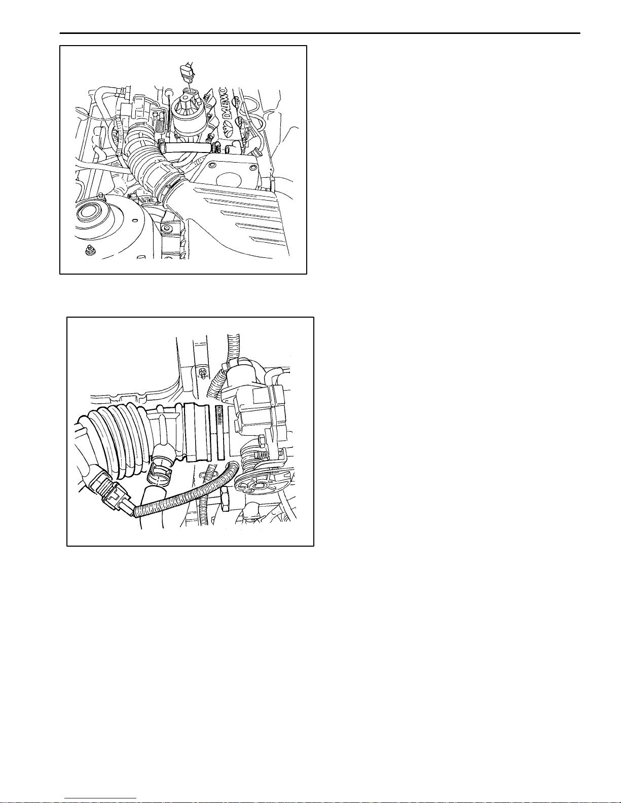
6. Disconnect the intake air temperature (IAT) sensor
connector.
7. Disconnect the breather tube from the valve cover.
8. Disconnect the air intake tube from the throttle body.
DAEWOO T-154 BL2,3
Page 26
1B–14 SOHC ENGINE MECHANICAL
A102B092
9. Disconnect the electronic ignition (EI) system ignition coil connector.
10. Disconnect the oxygen (O
) sensor connector.
2
11. Disconnect the fuel injector harness connectors.
12. Disconnect the idle air control (IAC) valve connector.
13. Disconnect the throttle position (TP) sensor connector.
14. Disconnect the engine coolant temperature (ECT)
sensor connector.
15. Disconnect the coolant temperature sensor (CTS)
connector.
16. Remove the camshaft position (CMP) sensor.
A102B016
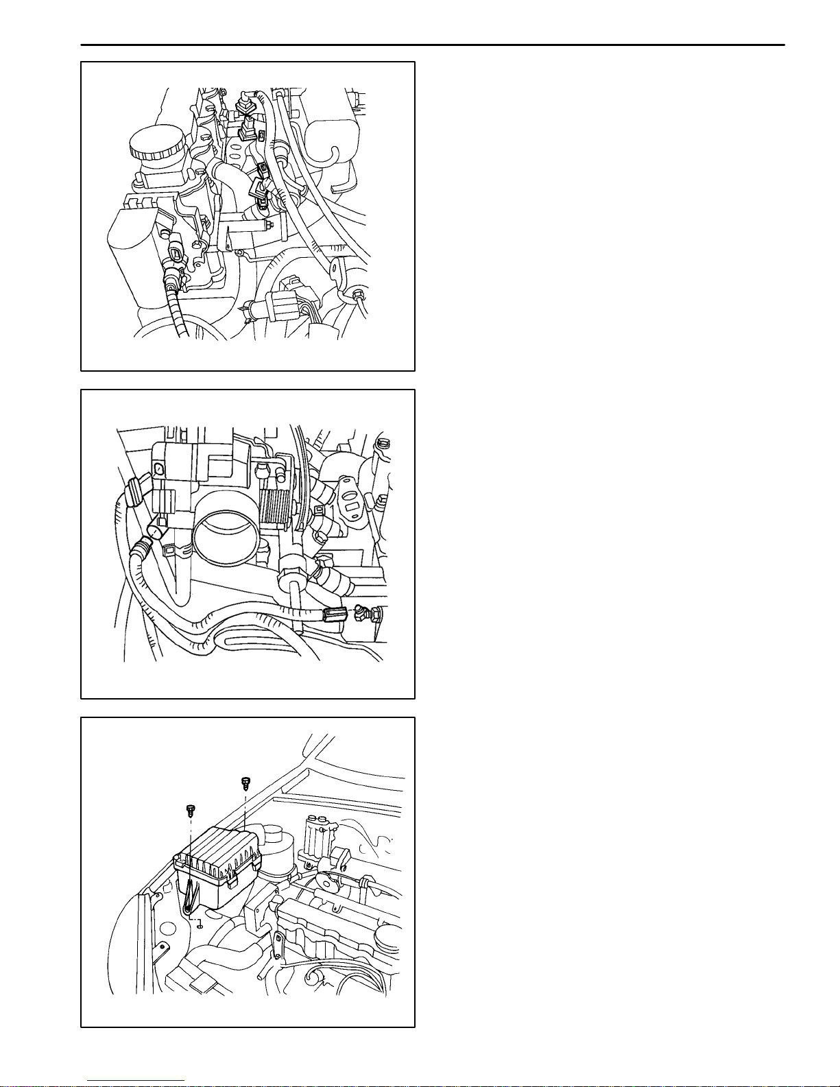
17. Remove the air cleaner housing bolts.
18. Remove the air cleaner housing.
A102B002
DAEWOO T-154 BL2,3
Page 27
A102B003
SOHC ENGINE MECHANICAL 1B–15
19. Remove the upper timing belt cover bolts.
20. Remove the upper timing belt cover.
21. Align the camshaft gear timing mark to the notch in
the rear timing belt cover.
DAEWOO T-154 BL2,3
A102B004
22. Remove the right front wheel. Refer to Section 2E,
Tires and Wheels.
23. Remove the right front wheel well splash shield.
24. Remove the A/C compressor drive belt, if equipped.
A102B006
Page 28
1B–16 SOHC ENGINE MECHANICAL
25. Remove the alternator drive belt.
26. Remove the power steering pump pulley bolts, if
equipped.
27. Remove the power steering pump pulley, if
equipped.
A102B005
28. Disconnect the fuel return line at the fuel pressure
regulator.
29. Disconnect the fuel feed line at the fuel rail.
A402B009
30. Remove the alternator adjusting bolt.
31. Remove the alternator adjusting bracket retaining
bolt.
32. Remove the alternator adjusting bracket.
A102B118
DAEWOO T-154 BL2,3
Page 29
A102B114
SOHC ENGINE MECHANICAL 1B–17
33. Disconnect the upper radiator hose at the thermostat housing.
34. Disconnect the brake booster vacuum hose at the
intake manifold.
35. Disconnect all of the necessary vacuum hoses.
36. Remove the crankshaft pulley bolt.
37. Remove the crankshaft pulley.
38. Remove the power steering pump, if equipped. Refer to Section 6B, Power Steering Pump.
39. Install the engine mount bracket-to-engine mount
retaining bolt s and tighten the bolts to secure the engine, if the power steering pump was removed.
40. Remove the lower timing belt cover bolts.
41. Remove the lower timing belt cover.
DAEWOO T-154 BL2,3
A102B008
42. Slightly loosen the coolant pump retaining bolts.
43. Rotate the coolant pump counterclockwise using the
timing belt adjuster J-42492 to relieve the timing belt
tension.
44. Remove the timing belt. Refer to “Timing Belt” in this
section.
A102B040
Page 30
1B–18 SOHC ENGINE MECHANICAL
45. Disconnect the crankcase ventilation tube at the
camshaft housing.
A402B004
46. Remove the valve cover bolts.
47. Remove the valve cover and the valve cover gasket.
A102B111
Notice: Take care to prevent any scratches, nicks or
damage to the camshaft.
48. While holding the camshaft firmly in place, remove
the camshaft gear bolt.
49. Remove the camshaft gear.
50. Remove the timing belt automatic tensioner bolt.
51. Remove the timing belt automatic tensioner.
52. Remove the rear timing belt cover bolts.
53. Remove the rear timing belt cover.
A102B046
DAEWOO T-154 BL2,3
Page 31

TAA1F480
SOHC ENGINE MECHANICAL 1B–19
54. Disconnect the ignition wires at the spark plugs.
55. Remove the retaining nuts from the auxiliary catalytic converter at the exhaust manifold flange.
56. Disconnect the heater inlet hose at the coolant distributor.
57. Disconnect the surge tank coolant hose at the
throttle body.
DAEWOO T-154 BL2,3
A102B119
58. Remove the intake manifold support bracket retaining bolts from the coolant distributor.
59. Disconnect the throttle cable at the throttle body and
the intake manifold.
A402B005
Page 32

1B–20 SOHC ENGINE MECHANICAL
60. Gradually loosen all of the cylinder head bolts in the
sequence shown.
61. Remove the cylinder head bolts.
62. Remove the camshaft carrier assembly.
Notice: Prevent any engine oil or coolant from entering
the cylinders when removing the cylinder head. Damage
to the engine could result.
63. Remove the cylinder head with the intake manifold
and the exhaust manifold attached.
64. Remove the cylinder head gasket.
A402B006
Cleaning Procedure
1. Clean the gasket surfaces of the cylinder head and
the engine block.
2. Make sure the gasket surfaces of the cylinder head
and the engine block are free of nicks and heavy
scratches.
3. Clean the cylinder head bolts.
4. Inspect the cylinder head for warpage. Refer to “Cyl-
inder Head and Valve Train Components” in this section.
A102B122
Installation Procedure
1. Apply a continuous 3 mm (0.12 inch) bead of gasket
maker to the sealing surface of the camshaft carrier.
2. Install the cylinder head gasket.
3. Install the cylinder head with the intake manifold and
the exhaust manifold attached.
4. Install the camshaft carrier assembly.
A402B007
DAEWOO T-154 BL2,3
Page 33

A402B008
SOHC ENGINE MECHANICAL 1B–21
5. Install the cylinder head bolts in the sequence shown.
Tighten
Tighten the cylinder head bolts in the sequence previously shown to 25 N m (18 lb-ft) using a torque
wrench. Use the angular torque gauge KM-470-B
to tighten the cylinder head bolts another 70 degrees
plus 70 degrees plus 30 degrees.
DAEWOO T-154 BL2,3
A102B172
6. Connect the throttle cable at the throttle body and at
the intake manifold.
7. Install the intake manifold support bracket retaining
bolt to the coolant distributor.
Tighten
Tighten the intake manifold support bracket retaining
bolts to 22 N m (16 lb-ft).
A102B029
Page 34

1B–22 SOHC ENGINE MECHANICAL
8. Connect the surge tank coolant hose at the throttle
body.
9. Connect the heater inlet hose to the coolant distributor.
A102B119
10. Install the auxiliary catalytic converter nuts at the exhaust manifold flange.
TAA1F480
Tighten
Tighten the auxiliary catalytic converter-to-exhaust
manifold nuts to 40 N m (30 lb-ft).
11. Connect the ignition wires at the spark plugs.
12. Install the rear timing belt cover.
13. Install the rear timing belt cover bolts.
Tighten
Tighten the rear timing belt cover bolts to 10 N m
(89 lb-in).
14. Install the timing belt automatic tensioner.
15. Install the timing belt automatic tensioner bolt.
Tighten
Tighten the timing belt automatic tensioner bolt to
20 N m (15 lb-ft).
A102B046
DAEWOO T-154 BL2,3
Page 35

A102B111
SOHC ENGINE MECHANICAL 1B–23
Notice: Take extreme care to prevent any scratches,
nicks, or damage to the camshaft. Such damage can impair vehicle operation.
16. Install the camshaft gear.
17. While holding the camshaft firmly in place, install the
camshaft gear bolt.
Tighten
Tighten the camshaft gear bolt to 45 N m (33 lb-ft ).
18. Install the valve cover and the valve cover gasket.
19. Install the valve cover bolts.
A402B004
Tighten
Tighten the valve cover bolts to 9 N m (80 lb-in).
20. Connect the crankcase ventilation tube to the camshaft housing.
21. Align the mark on the camshaft gear to the notch at
the top of the rear timing belt cover.
DAEWOO T-154 BL2,3
A102B004
Page 36

1B–24 SOHC ENGINE MECHANICAL
A102B030
A102B020
22. Align the mark on t h e crankshaft gear to the notch at
the bottom of the rear timing belt cover.
23. Install the timing belt. Refer to “Timing Belt” in this
section.
24. Check the timing belt tension. Refer to “Timing Belt
Check and Adjust” in this section.
25. Install the lower timing belt cover.
26. Install the lower timing belt cover bolts.
Tighten
Tighten the lower timing belt cover bolts to 10 N m
(89 lb-in).
27. Install the power steering pump and the bolts, if
equipped. Refer to Section 6B, Power Steering
Pump.
28. Install the engine mount bracket-to-engine mount retaining bolt s if the power steering pump was installed.
Tighten
Tighten the engine mount bracket-to-engine mount
retaining bolts to 60 N m (44 lb-ft).
29. Install the crankshaft pulley.
30. Install the crankshaft pulley bolt.
Tighten
Tighten the crankshaft pulley bolt to 95 N m (70 lb-ft)
using a torque wrench. Use the angular torque gauge
KM-470-B to tighten the crankshaft pulley bolt another 30 degrees plus 15 degrees.
31. Install the power steering pump pulley, if equipped.
32. Install the power steering pump pulley bolts, if
equipped.
Tighten
Tighten the power steering pump pulley bolts to
25 N m (18 lb-ft).
A102B005
DAEWOO T-154 BL2,3
Page 37

A102B114
SOHC ENGINE MECHANICAL 1B–25
33. Connect all of the vacuum hoses.
34. Connect the brake booster hose at the intake manifold.
35. Connect the upper radiator hose at the thermostat
housing.
36. Install the alternator adjusting bracket.
37. Install the alternator adjusting bracket retaining bolt.
A102B118
Tighten
Tighten the alternator adjusting bracket retaining bolt
to 25 N m (18 lb-ft).
38. Install the alternator adjusting bolt. Do not tighten.
39. Connect the fuel feed line at the fuel rail.
40. Connect the fuel return line at the fuel pressure regulator.
DAEWOO T-154 BL2,3
A402B009
Page 38

1B–26 SOHC ENGINE MECHANICAL
41. Install the alternator drive belt.
Tighten
Tighten the alternator adjusting bolt to 20 N m (15 lb-ft).
42. Install the upper timing belt cover.
43. Install the upper timing belt cover bolts.
Tighten
Tighten the upper timing belt cover bolts to 10 N m
(89 lb-in).
44. Install the A/C compressor drive belt, as necessary.
45. Install the right front wheel well splash shield.
46. Install the right front wheel. Refer to Section 2E,
Tires and Wheels.
A102B003
47. Install the air filter housing.
48. Install the air filter housing bolts.
A102B001
Tighten
Tighten the air filter housing bolts to 8 N m (71 lb-in).
49. Connect the air intake tube to the throttle body.
50. Connect the breather tube to the valve cover.
51. Connect the IAT sensor connector.
52. Install the CMP sensor.
53. Connect the CTS connector.
54. Connect the ECT sensor connector.
55. Connect the IAC valve connector.
56. Connect the TP sensor connector.
57. Connect the EI system ignition coil connector.
58. Connect the fuel injector harness connectors.
59. Connect the O2sensor connector.
60. Connect the ECM ground terminal at the intake manifold.
61. Connect the negative battery cable.
62. Install the fuel pump fuse.
63. Refill the engine cooling system. Refer to Section
1D, Engine Cooling.
A102B016
DAEWOO T-154 BL2,3
Page 39

A402B003
SOHC ENGINE MECHANICAL 1B–27
CAMSHAFT
Tools Required
KM-565-A Valve Spring Compressor
Removal Procedure
1. Remove the timing belt. Refer to “Timing Belt” in this
section.
2. Disconnect the air breather tube at the valve cover.
3. Remove the valve cover bolts.
4. Remove the valve cover.
5. Remove the valve cover gasket.
6. Install the valve spring compressor KM-565-A.
Notice: Take extreme care to prevent any scratches,
nicks, or damage to the camshaft. Such damage can impair vehicle operation.
A102B074
7. Remove the camshaft followers using the valve
spring compressor KM-565-A.
8. While holding the camshaft firmly in place, remove
the camshaft gear bolt.
9. Remove the camshaft gear.
DAEWOO T-154 BL2,3
A102B111
Page 40

1B–28 SOHC ENGINE MECHANICAL
10. Disconnect the positive battery cable from the battery.
11. Remove the battery and the battery tray. Refer to
Section 1E, Engine Electrical.
A102C034
12. Disconnect the electronic ignition (EI) system ignition coil connector.
13. Disconnect the EI system ignition wires at the ignition coil.
14. Remove the EI system ignition coil mounting bolts.
15. Remove the EI system ignition coil.
A102B075
16. Remove the EI system ignition coil mounting plate
bolts.
17. Remove the EI system ignition coil mounting plate.
18. Remove the camshaft pressure plate bolts.
19. Remove the camshaft pressure plate.
A102B076
DAEWOO T-154 BL2,3
Page 41

A102B077
SOHC ENGINE MECHANICAL 1B–29
20. Remove the camshaft.
Installation Procedure
1. Install the camshaft.
2. Install the camshaft pressure plate.
3. Install the camshaft pressure plate bolts.
A102B076
Tighten
Tighten the camshaft pressure plate bolts to 10 N m
(89 lb-in).
4. Measure camshaft end play. Camshaft end play
should be 0.04 to 0.16 mm (.016 to 0.64 inch).
5. Install the EI system ignition coil mounting plate.
6. Install the EI system ignition coil mounting plate
bolts.
Tighten
Tighten the EI system ignition coil mounting plate
bolts to 10 N m (89 lb-in).
7. Install the EI system ignition coil.
8. Install the EI system ignition coil mounting bolts.
DAEWOO T-154 BL2,3
A102B075
Tighten
Tighten the EI system ignition coil mounting bolts to
10 N m (89 lb-in).
9. Connect the ignition wires at the EI system ignition
coil.
10. Connect the EI system ignition coil connector.
Page 42

1B–30 SOHC ENGINE MECHANICAL
11. Install the battery and the battery tray. Refer to Sec-
tion 1E, Engine Electrical.
12. Connect the positive battery cable to the battery.
A102C034
Notice: Take extreme care to prevent any scratches,
nicks, or damage to the camshaft. Such damage can impair vehicle operation.
A102B111
13. Install the camshaft gear.
14. While holding the camshaft firmly in place, install the
camshaft gear bolt.
Tighten
Tighten the camshaft gear bolt to 45 N m (33 lb-ft).
15. Install the camshaft followers using the valve spring
compressor KM-565-A.
16. Remove the tool KM-565-A.
A102B074
DAEWOO T-154 BL2,3
Page 43

A402B003
SOHC ENGINE MECHANICAL 1B–31
17. Install the valve cover gasket.
18. Install the valve cover.
19. Install the valve cover bolts.
Tighten
Tighten the valve cover bolts to 9 N m (80 lb-in).
20. Connect the air breather tube to the valve cover.
21. Install the timing belt. Refer to “Timing Belt” in this
section.
TIMING BELT CHECK AND ADJUST
Tools Required
J-42492 Timing Belt Adjuster
KM-470-B Angular Torque Gauge
A102B001
Adjustment Procedure
1. Disconnect the negative battery cable.
2. Disconnect the intake air temperature (IAT) sensor
connector.
3. Disconnect the air intake tube from the throttle body.
4. Disconnect the breather tube from the valve cover.
5. Remove the air cleaner housing bolts.
6. Remove the air cleaner housing.
7. Remove the right front wheel. Refer to Section 2E,
Tires and Wheels.
8. Remove the right front wheel well splash shield.
DAEWOO T-154 BL2,3
A102B002
Page 44

1B–32 SOHC ENGINE MECHANICAL
9. Remove the A/C compressor drive belt, if equipped.
10. Remove the alternator drive belt.
11. Remove the power steering pump pulley bolts, if
equipped.
12. Remove the power steering pump pulley, if
equipped.
13. Remove the power steering pump mounting bolts,
if equipped.
14. Remove the upper timing belt cover bolts.
15. Remove the upper timing belt cover.
A102B003
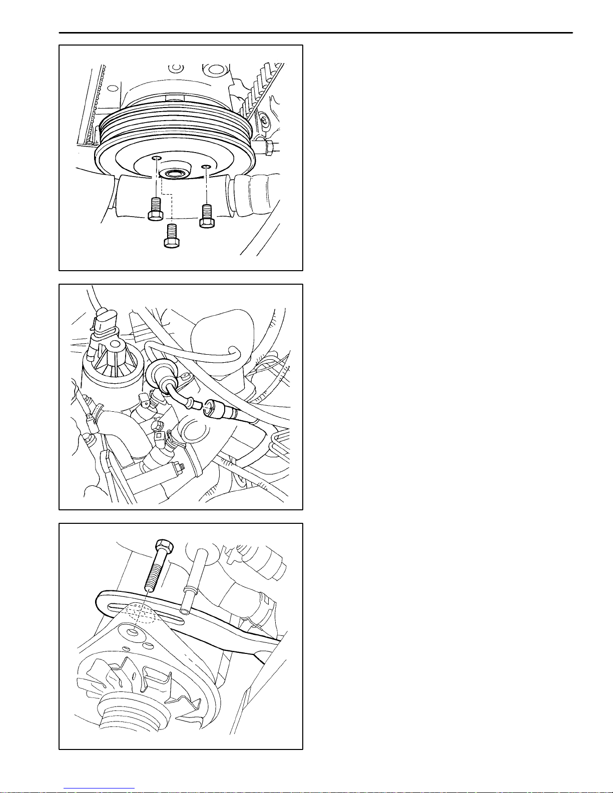
16. Remove the crankshaft pulley bolt.
17. Remove the crankshaft pulley.
A102B018
18. Remove the lower timing belt cover bolts.
19. Remove the lower timing belt cover.
A102B008
DAEWOO T-154 BL2,3
Page 45

A102B030
SOHC ENGINE MECHANICAL 1B–33
20. Install the crankshaft pulley bolt.
21. Rotate the crankshaft at least one full turn clockwise
using the crankshaft pulley bolt.
22. Align the dot on the crankshaft gear to the notch at
the bottom of the rear timing belt cover.
23. Align the camshaft gear timing mark to the notch at
the top of the rear timing belt cover.
DAEWOO T-154 BL2,3
A102B004
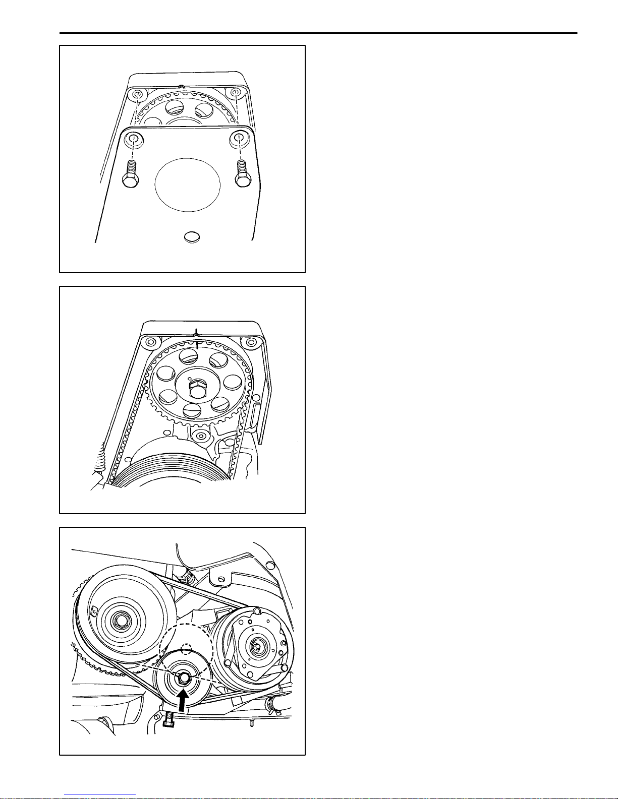
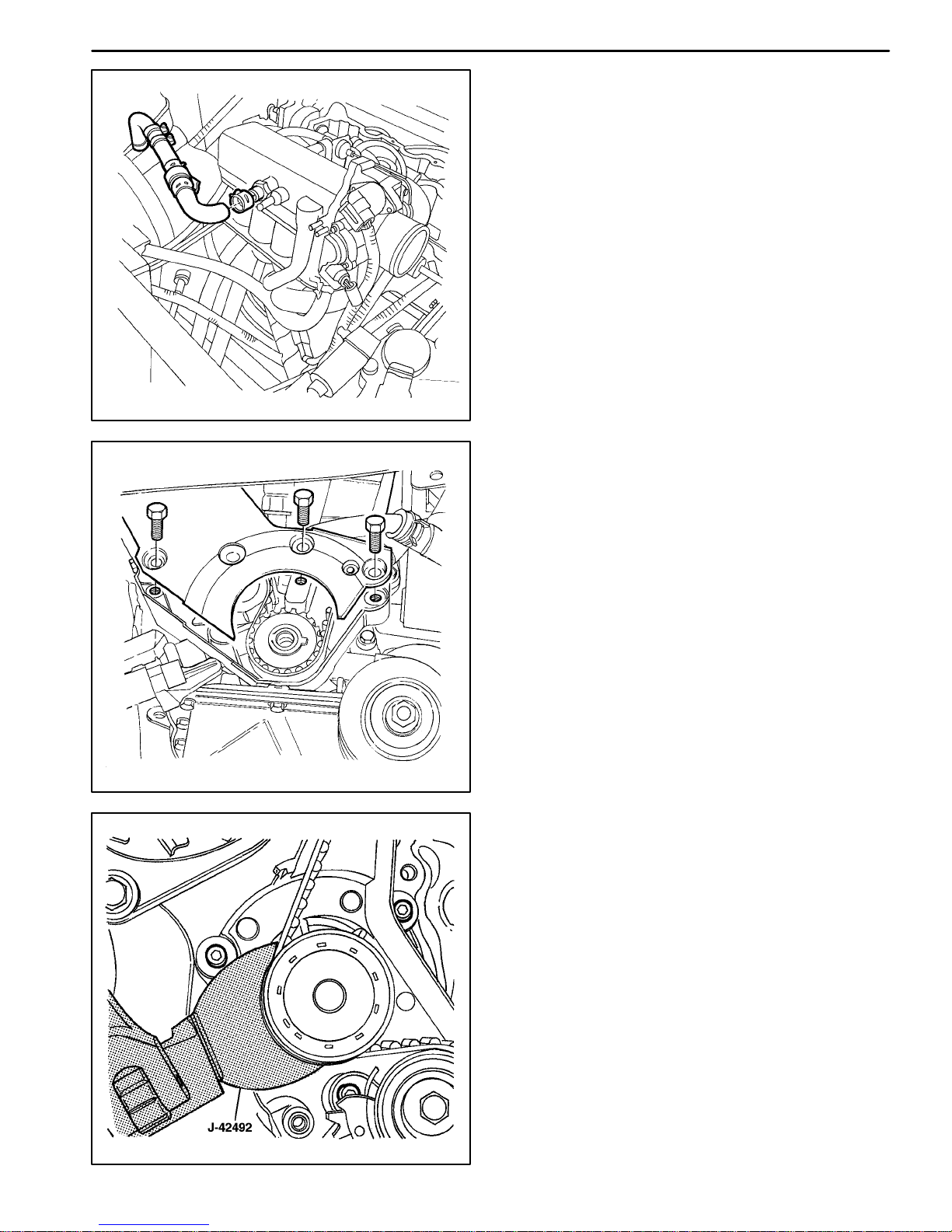
24. Slightly loosen the three coolant pump retaining
bolts.
25. Using the timing belt adjuster J-42492, rotate the
coolant pump clockwise to add the highest tension
to the timing belt.
26. Tighten the coolant pump retaining bolts loosely.
A102B040
Page 46

1B–34 SOHC ENGINE MECHANICAL
27. Align the adjust arm hole of the timing belt automatic
tensioner to the hole in the timing belt automatic tensioner bracket.
28. Insert a 4.5 mm driver through the adjust arm hole
and the tensioner bracket hole.
29. Rotate the crankshaft two full turns clockwise using
the crankshaft pulley bolt.
30. Rotate the crankshaft at least one full turn clockwise
using the crankshaft pulley bolt.
31. Remove the driver from the timing belt automatic
tensioner.
32. Loosen the coolant pump retaining bolts.
A102B039
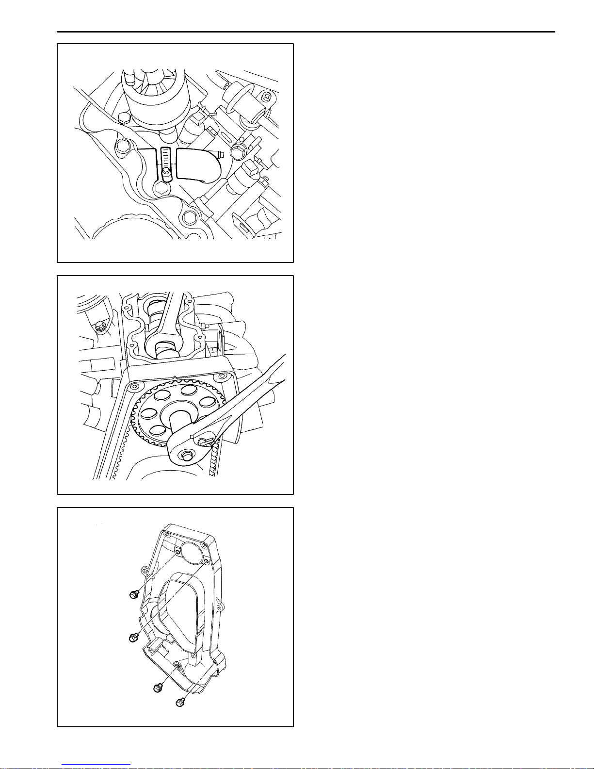
33. Rotate the coolant pump until the adjust arm pointer
of the timing belt automatic tensioner is aligned with
the notch in the timing belt automatic tensioner
bracket.
34. Tighten the coolant pump retaining bolts.
A102B041
Tighten
Tighten the coolant pump retaining bolts to 10 N m
(89 lb-in).
35. Remove the crankshaft pulley bolt.
36. Install the lower timing belt cover.
37. Install the lower timing belt cover bolts.
Tighten
Tighten the lower timing belt cover bolts to 10 N m
(89 lb-in).
A102B008
DAEWOO T-154 BL2,3
Page 47

A102B018
A102B005
SOHC ENGINE MECHANICAL 1B–35
38. Install the crankshaft pulley.
39. Install the crankshaft pulley bolt.
Tighten
Tighten the crankshaft pulley bolt to 95 N m (70 lb-ft)
using a torque wrench. Use the angular torque gauge
KM-470-B to tighten the crankshaft pulley bolt another 30 degrees plus 15 degrees.
40. Install the upper timing belt cover.
41. Install the upper timing belt cover bolts.
Tighten
Tighten the upper timing belt cover bolts to 10 N m
(89 lb-in).
42. Install the power steering pump mounting bolts, if
equipped.
Tighten
Tighten the power steering pump mounting bolts to
25 N m (18 lb-ft).
43. Install the power steering pump pulley, if equipped.
44. Install the power steering pump pulley bolts, if
equipped.
Tighten
Tighten the power steering pump pulley bolts to
25 N m (18 lb-ft).
DAEWOO T-154 BL2,3
45. Install the alternator drive belt.
Tighten
Tighten the alternator adjusting bolt to 25 N m (18 lbft).
46. Install the A/C compressor drive belt, if equipped.
47. Install the right front wheel well splash shield.
48. Install the right front wheel. Refer to Section 2E,
Tires and Wheels.
49. Install the air cleaner housing.
50. Install the air cleaner housing bolts.
Tighten
Tighten the air filter housing bolts to 8 N m (71 lb-in).
A102B002
Page 48

1B–36 SOHC ENGINE MECHANICAL
51. Connect the air intake tube to the throttle body.
52. Connect the breather tube to the valve cover.
53. Connect the IAT sensor connector.
54. Connect the negative battery cable.
A102B001
TIMING BELT
Tools Required
J-42492 Timing Belt Adjuster
KM-470-B Angular Torque Gauge
A102B001
Removal Procedure
1. Disconnect the negative battery cable.
2. Disconnect the intake air temperature (IAT) sensor
connector.
3. Disconnect the air intake tube from the throttle body.
4. Disconnect the breather tube from the valve cover.
5. Remove the air cleaner housing bolts.
6. Remove the air cleaner housing.
7. Remove the right front wheel. Refer to Section 2E,
Tires and Wheels.
8. Remove the right front wheel well splash shield.
A102B002
DAEWOO T-154 BL2,3
Page 49

A102B003
SOHC ENGINE MECHANICAL 1B–37
9. Remove the A/C compressor drive belt, if equipped.
10. Remove the alternator drive belt.
11. Remove the power steering pump, if equipped. Refer to Section 6B, Power Steering Pump.
12. Remove the upper timing belt cover bolts.
13. Remove the upper timing belt cover.
14. Remove the crankshaft pulley bolt.
15. Remove the crankshaft pulley.
16. Remove the lower timing belt cover bolts.
17. Remove the lower timing belt cover.
DAEWOO T-154 BL2,3
A102B008
18. Install the crankshaft pulley bolt.
19. Using the crankshaft pulley bolt, rotate the crankshaft clockwise until the mark on the crankshaft
gear is aligned with the notch at the bottom of the
rear timing belt cover.
A102B030
Page 50

1B–38 SOHC ENGINE MECHANICAL
20. Slightly loosen the coolant pump retaining bolts.
21. Using the timing belt adjuster J-42492, rotate the
coolant pump counterclockwise to release the tension on the timing belt.
22. Remove the timing belt.
A102B040
Installation Procedure
1. Align the mark on the crankshaft gear to the notch on
the bottom of the rear timing belt cover.
2. Align the mark on the camshaft gear to the notch on
the top of the rear timing belt cover.
3. Install the timing belt.
A102B042
4. Using the timing belt adjuster J-42492, rotate the
coolant pump clockwise to add the highest tension to
the timing belt.
5. Tighten the coolant pump retaining bolts loosely.
A102B040
DAEWOO T-154 BL2,3
Page 51

A102B039
SOHC ENGINE MECHANICAL 1B–39
6. Align the adjust arm hole of the timing belt automatic
tensioner to the hole in the timing belt automatic tensioner bracket.
7. Insert a 4.5 mm driver through the adjust arm hole
and the tensioner bracket hole.
8. Rotate the crankshaft two full turns clockwise using
the crankshaft pulley bolt.
9. Align the mark on th e crankshaft gear to the notch at
the bottom of the rear timing belt cover.
DAEWOO T-154 BL2,3
A102B030
10. Remove the driver from the timing belt automatic
tensioner.
11. Slightly loosen the three coolant pump retaining
bolts.
12. Using the timing belt adjuster J-42492, rotate the
coolant pump.
A102B040
Page 52

1B–40 SOHC ENGINE MECHANICAL
13. Rotate the coolant pump until the adjust arm pointer
of the timing belt automatic tensioner is aligned with
the notch in the timing belt automatic tensioner
bracket.
14. Tighten the coolant pump retaining bolts.
Tighten
Tighten the coolant pump retaining bolts to 10 N m
(89 lb-in).
A102B041
15. Remove the crankshaft pulley bolt.
16. Install the lower timing belt cover.
17. Install the lower timing belt cover bolts.
A102B008
Tighten
Tighten the lower timing belt cover bolts to 10 N m
(89 lb-in).
18. Install the crankshaft pulley.
19. Install the crankshaft pulley bolt.
Tighten
Tighten the crankshaft pulley bolt to 95 N m (70 lb-ft)
using a torque wrench. Using the angular torque
gauge KM-470-B, tighten the crankshaft pulley bolt
another 30 degrees plus 15 degrees.
A102B018
DAEWOO T-154 BL2,3
Page 53

A102B003
SOHC ENGINE MECHANICAL 1B–41
20. Install the upper timing belt cover.
21. Install the upper timing belt cover bolts.
Tighten
Tighten the upper timing belt cover bolts to 10 N m
(89 lb-in).
22. Install the power steering pump, if equipped. Refer
to Section 6B, Power Steering Pump.
23. Install the alternator drive belt.
24. Install the A/C compressor drive belt, if equipped.
DAEWOO T-154 BL2,3
A102B006
25. Install the right front wheel well splash shield.
26. Install the right front wheel. Refer to Section 2E,
Tires and Wheels.
27. Install the air filter housing.
28. Install the air filter housing bolts.
Tighten
Tighten the air filter housing b olts to 8 N m (71 lb-in).
A102B002
Page 54

1B–42 SOHC ENGINE MECHANICAL
29. Connect the air intake tube to the throttle body.
30. Connect the breather tube to the valve cover.
31. Connect the IAT sensor connector.
32. Connect the negative battery cable.
A102B001
OIL PUMP
Tools Required
KM-498-B Pressure Gauge
KM-135 Adapter
A102B019
Engine Oil Pressure Inspection Procedure
1. Remove the right-hand wheel well splash shield.
2. Remove the oil pressure switch connector.
3. Install the adapter KM-135 in place of the oil pressure
switch.
4. Connect the pressure gauge KM-498-B to the adapt-
er.
5. Start the engine and check the oil pressure at idle
speed and an engine temperature of 80 C (176 F).
Important: The minimum oil pressure should be 30 kPa
(8.88 psi).
6. Stop the engine and remove the oil pressure gauge
and the adapter.
A202B003
DAEWOO T-154 BL2,3
Page 55

A102B019
SOHC ENGINE MECHANICAL 1B–43
7. Install the oil pressure switch.
Tighten
Tighten the oil pressure switch to 40 N m (30 lb-ft).
8. Connect the electrical connector to the oil pressure
switch.
9. Install the right-hand wheel well splash shield.
10. Check the oil level and fill the oil to the FULL mark.
Removal Procedure
1. Disconnect the negative battery cable.
2. Remove the power steering pump, if equipped. Refer to Section 6A, Power Steering System.
3. Remove the timing belt. Refer to “Timing Belt” in this
section.
4. Remove the rear timing belt cover. Refer to “Rear
Timing Belt Cover” in this section.
5. Disconnect the oil pressure switch connector.
DAEWOO T-154 BL2,3
A102B019
6. Remove the crankshaft position (CKP) sensor bolt.
7. Remove the CKP sensor.
8. Remove the oil pan. Refer to “Oil Pan” in this section.
9. Remove the oil pump pickup tube and the support
bracket bolts.
10. Remove the oil pump pickup tube.
A102B064
Page 56

1B–44 SOHC ENGINE MECHANICAL
11. Remove the oil pump retaining bolts.
12. Carefully separate the oil pump and the gasket from
the engine block and the oil pan.
13. Remove the oil pump.
A102B065
Inspection Procedure
1. Clean the oil pump and the engine block gasket mat-
ing surfaces.
2. Remove the safety relief valve bolt.
3. Remove the safety relief valve and the spring.
4. Remove the oil pump-to-crankshaft seal.
A202B002
5. Remove the oil pump rear cover bolts.
6. Remove the rear cover.
A202B001
DAEWOO T-154 BL2,3
Page 57

SOHC ENGINE MECHANICAL 1B–45
7. Clean the oil pump housing and all of the parts.
8. Inspect all of the parts for signs of wear. Refer to
“Engine Specifications” in this section.
9. Coat all of the oil pump parts with clean engine oil.
10. Reinstall all of the oil pump parts.
Notice: Pack the oil pump gear cavity with petroleum
jelly to ensure an oil pump prime. Failure to do this can
damage the engine.
11. Install the oil pump rear cover and the bolts.
Tighten
Tighten the oil pump rear cover bolts to 6 N m (53 lbin).
12. Install the safety relief valve, the spring, the washer,
and the bolt.
A202B001
Tighten
Tighten the oil pump safety relief valve bolt to 30 N m
(22 lb-ft).
Installation Procedure
1. Apply a bead of room temperature vulcanizing (RTV)
sealer to the oil pump gasket.
2. Install a new oil pump gasket to the oil pump.
3. Coat the threads of the oil pump bolts with Loctite
573.
4. Install the oil pump to the engine block with the bolts.
DAEWOO T-154 BL2,3
Tighten
Tighten the oil pump retaining bolts to 10 N m (89 lbin).
A102B065
Page 58

1B–46 SOHC ENGINE MECHANICAL
5. Install a new oil pump to the crankshaft shaft seal.
6. Coat the lip of the seal with a thin coat of grease.
A202B002
7. Coat the threads of the oil pump pickup tube and the
support bracket bolts with Loctite 573.
8. Install the oil pump pickup tube and the bolts.
A102B064
Tighten
Tighten the oil pump pickup tube and the support
bracket bolts to 10 N m (89 lb-in).
9. Install the oil pan. Refer to “Oil Pan” in this section.
10. Install the CKP sensor and the bolt.
Tighten
Tighten the crankshaft position sensor retaining bolt
to 10 N m (89 lb-in).
11. Connect the oil pressure switch connector.
12. Install the rear timing belt cover. Refer to “Rear Timing Belt Cover” in this section.
13. Install the timing belt. Refer to “Timing Belt” In this
section.
14. Install the power steering pump, if equipped. Refer
to Section 6A, Power Steering System.
15. Connect the negative battery cable.
A102B019
DAEWOO T-154 BL2,3
Page 59

TAA1F480
SOHC ENGINE MECHANICAL 1B–47
OIL PAN
Removal Procedure
1. Disconnect the negative battery cable.
2. Drain the engine oil from the engine crankcase.
3. Disconnect the post-converter heated oxygen (O2)
sensor.
4. Remove the auxiliary catalytic converter upper flange
nuts from the exhaust manifold and the bolts from the
bracket.
5. Remove the nuts from the front muffler pipe to the
main catalytic converter.
6. Remove both catalytic converters as a unit.
DAEWOO T-154 BL2,3
B102G003
7. Remove the flywheel or flexible plate inspection cover
bolts.
8. Remove the flywheel or flexible plate inspection cov-
er.
A102B021
Page 60

1B–48 SOHC ENGINE MECHANICAL
9. Remove the oil pan retaining bolts.
10. Remove the oil pan from the engine block.
A102B043
Cleaning Procedure
1. Clean the oil pan sealing surface.
2. Clean the engine block sealing surface.
3. Clean the oil pan retaining bolts.
4. Clean the oil pan retaining bolt holes in the engine
block.
A102B044
Installation Procedure
1. Install the oil pan gasket to the oil pan.
2. Install the oil pan to the engine block.
Important: Install the oil pan within 5 minutes after applying liquid gasket to the oil pan.
3. Install the oil pan retaining bolts.
Tighten
Tighten the oil pan retaining bolts to 10 N m (89 lb-in).
A102B043
DAEWOO T-154 BL2,3
Page 61

A102B021
SOHC ENGINE MECHANICAL 1B–49
4. Install the flywheel or flexible plate inspection cover.
5. Install the flywheel or flexible plate inspection cover
bolts.
Tighten
Tighten the flywheel inspection cover bolts to 12 N m
(106 lb-in) or the flexible plate inspection cover bolts
to 10 N m (89 lb-in).
6. Install the catalytic converters.
Tighten
Tighten the auxiliary catalytic converter-to-exhaust
manifold nuts and bracket bolts to 40 N m (30 lb-ft).
DAEWOO T-154 BL2,3
TAA1F480
Tighten
Tighten the front muffler-to-main catalytic converter
nuts to 30 N m (22 lb-ft).
7. Connect the post-converter heated oxygen sensor
connector.
8. Connect the negative battery cable.
9. Install the oil pan drain plug.
Tighten
Tighten the oil pan drain plug to 55 N m (41 lb-ft).
10. Refill the engine crankcase with engine oil.
B102G003
Page 62

1B–50 SOHC ENGINE MECHANICAL
ENGINE MOUNT
Tools Required
KM-263-B Engine Assembly Support Fixture
Removal Procedure
1. Disconnect the negative battery cable.
2. Support the engine assembly using the engine assembly support fixture KM-263-B.
A105B012
3. Remove the engine mount bracket retaining bolts.
A102B020
4. Remove the engine mount attaching nuts.
5. Remove the engine mount.
A102B045
DAEWOO T-154 BL2,3
Page 63

A102B045
SOHC ENGINE MECHANICAL 1B–51
Installation Procedure
1. Install the engine mount.
2. Install the engine mount attaching nuts.
Tighten
Tighten the engine mount attaching nuts to 40 N m
(30 lb-ft).
3. Install the engine mount bracket retaining bolts.
Tighten
Tighten the engine mount bracket retaining bolts to
60 N m (44 lb-ft).
DAEWOO T-154 BL2,3
A102B020
4. Remove the engine assembly support fixture
KM-263-M
5. Connect the negative battery cable.
A105B012
Page 64

1B–52 SOHC ENGINE MECHANICAL
d
INTAKE MANIFOLD
Removal Procedure
1. Remove the fuel pump fuse.
2. Start the engine. After it stalls, crank the engine for
10 seconds to rid the fuel system of fuel pressure.
3. Disconnect the negative battery cable.
4. Disconnect the engine control module (ECM) groun
terminal from the intake manifold.
5. Drain the engine coolant. Refer to Section 1D, En-
gine Cooling.
6. Disconnect the intake air temperature (IAT) sensor
connector.
7. Disconnect the air intake tube from the throttle body.
A102B001
8. Disconnect the idle air control valve (IAC) connector.
9. Disconnect the throttle position (TP) sensor connector.
10. Disconnect the engine coolant temperature (ECT)
sensor connector.
A102B016
DAEWOO T-154 BL2,3
Page 65

A102B031
SOHC ENGINE MECHANICAL 1B–53
11. Disconnect the heater inlet hose from the coolant
distributor beneath the intake manifold.
12. Disconnect the surge tank coolant hose at the
throttle body.
13. Disconnect all of the necessary vacuum hoses, including the vacuum hose at the fuel pressure regulator and the brake booster vacuum hose at the
intake manifold.
14. Disconnect the throttle cable from the throttle body
and the intake manifold.
15. Remove the two throttle cable bracket bolts and the
throttle cable bracket.
16. Disconnect the fuel return line from the fuel pressure
regulator.
17. Disconnect the fuel feed line from the fuel rail.
DAEWOO T-154 BL2,3
A402B009
18. Disconnect the fuel injector connectors from the fuel
injectors.
19. Remove the two retaining bolts from the fuel injector
rail.
20. Remove the fuel injector rail and fuel injectors as an
assembly. Refer to Section 1F, Engine Controls.
A402B010
Page 66

1B–54 SOHC ENGINE MECHANICAL
21. Remove the alternator drive belt.
22. Remove the alternator adjusting bracket and the
bolts.
A102B118
23. Remove the three intake manifold support bracket
retaining bolts from the coolant distributor and the
engine block.
24. Remove the intake manifold support bracket.
A102B033
25. Remove the intake manifold retaining nuts and the
engine lift bracket bolt in the sequence shown.
A102B036
DAEWOO T-154 BL2,3
Page 67

A102B034
SOHC ENGINE MECHANICAL 1B–55
26. Remove the intake manifold.
27. Remove the intake manifold gasket.
28. Clean the sealing surfaces of the intake manifold
and the cylinder head.
Installation Procedure
1. Install the intake manifold gasket.
2. Install the intake manifold.
3. Install the intake manifold retaining nuts and the en-
gine lift bracket bolt in the sequence shown.
A102B035
Tighten
Tighten the intake manifold retaining nuts in the sequence shown to 25 N m (18 lb-ft).
Tighten the e ngine l ift bracket bolt t o 2 5 N m (18 lb-ft).
4. Install the intake manifold support bracket.
5. Install the intake manifold support bracket retaining
bolts.
Tighten
Tighten the intake manifold support bracket retaining
bolts to 22 N m (16 lb-ft).
6. Install the alternator adjusting bracket and the bolts.
Tighten
Tighten the alternator adjusting bracket retaining
bolts to 25 N m (18 lb-ft).
7. Install the alternator drive belt.
DAEWOO T-154 BL2,3
A102B118
Page 68

1B–56 SOHC ENGINE MECHANICAL
8. Install the fuel rail and the fuel injectors as an assem-
bly. Refer to Section 1F, Engine Controls.
9. Install the fuel rail retaining bolts.
Tighten
Tighten the f uel r ail r etaining b olts to 2 5 N m (18 lb-ft).
A402B010
10. Connect the fuel return line to the fuel pressure regulator.
11. Connect the fuel feed line to the fuel rail.
12. Install the throttle cable bracket and the two throttle
cable bracket bolts.
A402B005
Tighten
Tighten the throttle cable bracket bolts to 8 N m
(71 lb-in).
13. Connect the throttle cable to the intake manifold and
the throttle body.
14. Connect the fuel injector connectors to the fuel injectors.
15. Connect all of the vacuum lines that were previously
disconnected.
16. Connect the heater inlet hose to the coolant distributor beneath the intake manifold.
17. Connect the surge tank coolant hose to the throttle
body.
18. Connect the ECT sensor connector.
19. Connect the IAC valve connector.
20. Connect the throttle position sensor connector.
A102B016
DAEWOO T-154 BL2,3
Page 69

A102B001
SOHC ENGINE MECHANICAL 1B–57
21. Connect the air intake tube to the throttle body.
22. Connect the IAT sensor connector.
23. Connect the ECM ground terminal to the intake manifold.
24. Connect the negative battery cable.
25. Install the fuel pump fuse.
26. Refill the engine cooling system. Refer to Section
1D, Engine Cooling.
EXHAUST MANIFOLD
Removal Procedure
1. Disconnect the negative battery cable.
2. Disconnect the ignition wires from the spark plugs.
3. Disconnect the oxygen (O2) sensor.
4. Remove the exhaust manifold heat shield bolts.
5. Remove the exhaust manifold heat shield.
6. Remove the auxiliary catalytic converter upper
flange nuts.
DAEWOO T-154 BL2,3
TAA1F480
7. Remove the eight exhaust manifold nuts in the sequence shown.
8. Remove the exhaust manifold.
9. Remove the exhaust manifold gasket.
10. Clean the sealing surfaces of the exhaust manifold
and the cylinder head.
A102B037
Page 70

1B–58 SOHC ENGINE MECHANICAL
Installation Procedure
1. Install the exhaust manifold gasket.
2. Install the exhaust manifold.
3. Install the eight exhaust manifold nuts and torque in
the sequence shown.
Tighten
Tighten the exhaust manifold nuts 25 N m (18 lb-ft).
A102B038
4. Install the auxiliary catalytic converter-to-exhaust
manifold nuts.
TAA1F480
Tighten
Tighten the auxiliary catalytic converter-to-exhaust
manifold nuts to 50 N m (37 lb-ft).
5. Install the exhaust manifold heat shield.
6. Install the exhaust manifold heat shield bolts.
Tighten
Tighten the exhaust manifold heat shield bolts to
15 N m (11 lb-ft).
7. Connect the O2 sensor.
8. Connect the ignition wires to the spark plugs.
9. Connect the negative battery cable.
CAMSHAFT GEAR
Removal Procedure
1. Disconnect the negative battery cable.
2. Remove the timing belt. Refer to “Timing Belt” in this
section.
3. Remove the valve cover bolts.
4. Remove the valve cover.
A402B003
DAEWOO T-154 BL2,3
Page 71

A102B111
SOHC ENGINE MECHANICAL 1B–59
Notice: Take extreme care to prevent any scratches,
nicks, or damage to the camshaft. Such damage can impair vehicle operation.
5. While holding the camshaft firmly in place, remove
the camshaft gear bolt.
6. Remove the camshaft gear.
Installation Procedure
Notice: Take extreme care to prevent any scratches,
nicks, or damage to the camshaft. Such damage can impair vehicle operation.
A102B111
1. Install the camshaft gear.
2. While holding the camshaft firmly in place, install the
camshaft gear bolt.
Tighten
Tighten the camshaft gear bolt to 45 N m (33 lb-ft).
3. Install the valve cover.
4. Install the valve cover bolts.
Tighten
Tighten the valve cover bolts to 9 N m (80 lb-in).
5. Install the timing belt. Refer to “Timing Belt” in this
section.
6. Connect the negative battery cable.
DAEWOO T-154 BL2,3
A402B003
Page 72

1B–60 SOHC ENGINE MECHANICAL
REAR TIMING BELT COVER
Removal Procedure
1. Disconnect the negative battery cable.
2. Remove the timing belt. Refer to “Timing Belt” in this
section.
Notice: Take extreme care to prevent any scratches,
nicks, or damage to the camshaft. Such damage can impair vehicle operation.
3. Remove the camshaft gear. Refer to “Camshaft
Gear” in this section.
4. Remove the timing belt automatic tensioner bolt.
5. Remove the timing belt automatic tensioner.
6. Remove the rear timing belt cover bolts.
7. Remove the rear timing belt cover.
A102B046
Installation Procedure
1. Install the rear timing belt cover.
2. Install the rear timing belt cover bolts.
A102B041
Tighten
Tighten the rear timing belt cover bolts to 10 N m
(89 lb-in).
3. Install the timing belt automatic tensioner.
4. Install the timing belt automatic tensioner bolt.
Tighten
Tighten the timing belt automatic tensioner bolt to
20 N m (15 lb-ft).
Notice: Take extreme care to prevent any scratches,
nicks, or damage to the camshaft. Such damage can impair vehicle operation.
5. Install the camshaft gear. Refer to “Camshaft Gear”
in this section.
6. Install the timing belt. Refer to “Timing Belt” in this
section.
7. Connect the negative battery cable.
DAEWOO T-154 BL2,3
Page 73

SOHC ENGINE MECHANICAL 1B–61
ENGINE
Tools Required
KM-470-B Angular Torque Gauge
Removal Procedure
Important: On vehicles equipped with a manual trans-
axle, the manual transaxle must be removed before engine removal. Refer to Section 5B, Five-Speed Manual
Transaxle.
1. Remove the fuel pump fuse.
2. Start the engine. After it stalls, crank the engine for
10 seconds to rid the fuel system of fuel pressure.
3. Remove the hood. Refer to Section 9R, Body Front
End.
4. Drain the engine oil.
5. Disconnect the negative battery cable.
6. Disconnect and separate the battery positive cable.
7. Disconnect the negative battery cable from the vehicle frame.
DAEWOO T-154 BL2,3
A102B013
8. Discharge the air conditioning (A/C) system, if
equipped. Refer to Section 7B, Manual Control
Heating, Ventilation, and Air Conditioning System.
9. Disconnect the intake air temperature (IAT) sensor
connector.
10. Remove the air intake tube from the throttle body
and the air filter housing.
11. Disconnect the breather tube from the valve cover.
A402B002
Page 74

1B–62 SOHC ENGINE MECHANICAL
12. Remove the right front wheel. Refer to Section 2E,
Tires and Wheels.
13. Remove the right front wheel well splash shield.
14. Remove the A/C compressor drive belt, if equipped.
15. Remove the alternator drive belt.
16. Remove the power steering pump pulley bolts.
17. Remove the power steering pump pulley.
A102B014
18. Drain the engine coolant. Refer to Section 1D, Engine Cooling.
19. Remove the cooling system radiator and the engine
cooling fans. Refer to Section 1D, Engine Cooling.
20. Disconnect the upper radiator hose from the thermostat housing.
21. Disconnect the coolant surge tank hose from the radiator.
22. Disconnect the power steering return hose from the
power steering pump, if equipped.
23. Drain the power steering system, if equipped.
24. Disconnect the power steering pressure hose from
the power steering pump, if equipped.
A102B015
A102B016
25. Disconnect the electrical connector at the electronic
ignition (EI) system ignition coil, and the engine ECM
ground terminal at the intake manifold and at the
starter motor.
26. Disconnect the pre-converter oxygen (O2) sensor
connector.
27. Disconnect the electrical connectors at the fuel injectors.
28. Disconnect the idle air control (IAC) valve connector.
29. Disconnect the throttle position (TP) sensor connector.
30. Disconnect the engine coolant temperature (ECT)
sensor connector.
31. Disconnect the coolant temperature sensor (CTS)
connector and the knock sensor, if equipped.
DAEWOO T-154 BL2,3
Page 75

A402B009
SOHC ENGINE MECHANICAL 1B–63
32. Disconnect the alternator voltage regulator connector.
33. Disconnect all of the necessary vacuum lines, including the brake booster vacuum hose.
34. Disconnect the fuel return line at the fuel pressure
regulator.
35. Disconnect the fuel feed line at the fuel rail.
36. Disconnect the throttle cable from the throttle body
and the intake manifold bracket.
37. Disconnect the camshaft position (CMP) sensor
connector.
38. Disconnect the surge tank coolant hose at the
throttle body.
39. Disconnect the heater inlet hose from the coolant
distributor.
40. Disconnect the heater outlet hose at the coolant
pipe.
41. Disconnect the surge tank coolant hose from the
coolant pipe.
42. Disconnect the lower radiator hose at the coolant
pipe.
DAEWOO T-154 BL2,3
A102B017
43. Disconnect the starter solenoid “S” terminal wire.
44. Remove the A/C compressor hose assembly retaining bolt.
45. Disconnect the A/C compressor hose assembly
from the compressor.
46. Disconnect the A/C compressor coil connector.
47. Remove the A/C compressor mounting bolts.
48. Remove the A/C compressor.
49. Remove the A/C compressor mounting bracket
bolts.
50. Remove the A/C compressor mounting bracket from
the engine block.
A102B025
Page 76

1B–64 SOHC ENGINE MECHANICAL
51. Remove the auxiliary catalytic converter nuts from
the exhaust manifold and the bolts at the bracket.
TAA1F480
52. Remove the nuts from the front muffler pipe to the
main catalytic converter.
53. Remove both catalytic converters as a unit.
B102G003
54. Remove the engine crankshaft pulley bolt.
55. Remove the engine crankshaft pulley.
A102B018
DAEWOO T-154 BL2,3
Page 77

A102B019
SOHC ENGINE MECHANICAL 1B–65
56. Disconnect the vacuum lines at the evaporative
(EVAP) emission canister purge.
57. Disconnect the electrical connector at the EVAP
emission canister purge solenoid and the knock
sensor.
58. Disconnect the electrical connector at the oil pressure switch.
59. Disconnect the crankshaft position (CKP) sensor
connector and the CMP sensor connector.
60. Remove the CKP sensor retaining bolt.
61. Remove the CKP sensor.
62. Remove the right transaxle brace bolts from the
transaxle.
63. Remove the flywheel or the flexible plate inspection
cover bolts.
64. Remove the flywheel or the flexible plate inspection
cover.
DAEWOO T-154 BL2,3
A102B021
65. Remove the transaxle torque converter bolts on vehicles with an automatic transaxle.
A102B022
Page 78

1B–66 SOHC ENGINE MECHANICAL
66. Remove the transaxle bell housing bolts.
67. S upport the transaxle with a floor jack .
68. Install the engine lifting device.
69. Disconnect the right engine mount bracket from the
rubber engine mount by removing the two retaining
bolts.
70. Rem ove the right engine mount br acket from the engine block.
71. Separate the engine block from the transaxle.
72. Rem ove the engine.
73. Transfer any necessary parts.
A102B020
Installation Procedure
1. Install the engine into the engine compartment.
2. Align the transaxle alignment pins to the transaxle.
3. Install the transaxle bell housing bolts.
A102B063
Tighten
Tighten the transaxle bell housing bolts to 75 N m
(55 lb-ft).
4. Install the right engine mount bracket to the engine
block.
5. Install the right engine mount bracket retaining bolts
to the engine block.
Tighten
Tighten the engine mount bracket retaining bolts to
60 N m (44 lb-f t ) .
6. Install the engine mount-to-bracket retaining bolts.
Tighten
Tighten the engine mount bracket-to-engine mount
retaining bolts to 60 N m (44 lb-ft).
7. Remove the floor jack used for support of the tr ans-
axle.
8. Remove the engine lifting device.
A102B020
DAEWOO T-154 BL2,3
Page 79

A102B022
SOHC ENGINE MECHANICAL 1B–67
9. Install the transaxle torque converter bolts, if the ve-
hicle has an automatic transaxle.
Tighten
Tighten the transaxle torque converter bolts to 65 N m
(48 lb-ft).
10. Install the flywheel or the flexible plate inspection
cover.
A102B024
11. Install the flywheel or the flexible plate inspection
cover bolts.
Tighten
Tighten the flywheel inspection cover bolts to 12 N m
(106 lb-in) or the flexible plate inspection cover bolts
to 10 N m (89 lb-in).
12. Install the right transaxle brace bolts to the transaxle.
Tighten
Tighten the right transaxle brace bolts to 60 N m
(44 lb-ft).
13. Connect the vacuum lines at the EVAP emission
canister purge solenoid.
14. Connect the electrical connectors at the EVAP
emission canister purge solenoid.
DAEWOO T-154 BL2,3
Page 80

1B–68 SOHC ENGINE MECHANICAL
15. Connect the oil pressure switch connector.
16. Install the crankshaft pulley.
17. Install the crankshaft pulley bolt.
Tighten
Tighten the crankshaft pulley bolt to 95 N m (70 lb-ft)
using a torque wrench. Using the angular torque
gauge KM-470-B, tighten the crankshaft pulley bolt
another 30 degrees plus 15 degrees.
A102B018
18. Install the CKP sensor and the CKP sensor retaining
bolt.
B102G003
Tighten
Tighten the crankshaft position sensor retaining bolt
to 10 N m (89 lb-in).
19. Connect the CKP sensor connector.
20. Install the catalytic converters.
Tighten
Tighten the front muffler-to-main catalytic converter
nuts to 30 N m (22 lb-ft).
Tighten
Tighten the auxiliary catalytic converter-to-exhaust
manifold nuts and the bracket bolts to 40 N m (30 lbft).
TAA1F480
DAEWOO T-154 BL2,3
Page 81

A102B015
A102B025
SOHC ENGINE MECHANICAL 1B–69
21. Connect the power steering pressure hose, if
equipped.
22. Connect the power steering return hose, if
equipped.
23. Install the A/C compressor mounting bracket, if
equipped.
24. Install the A/C compressor mounting bracket bolts, if
equipped.
Tighten
Tighten the A/C compressor mounting bracket bolts
to 50 N m (37 lb-ft).
25. Install the A/C compressor, if equipped.
26. Install the A/C compressor mounting bolts, if
equipped.
Tighten
Tighten the A/C compr essor mount ing bolts to 27 N m
(20 lb-ft).
27. Connect the A/C compressor coil connector.
28. Install the alternator drive belt.
29. Install the A/C compressor drive belt, if equipped.
DAEWOO T-154 BL2,3
30. Connect the A/C compressor hose assembly and
the A/C compressor hose assembly retaining bolt,
if equipped.
Tighten
Tighten the A/C compressor hose assembly retaining
bolt to 33 N m (24 lb-ft).
31. Install the power steering pump pulley, if equipped.
32. Install the power steering pump pulley bolts, if
equipped.
Tighten
Tighten the power steering pump pulley bolts to
25 N m (18 lb-ft).
A102B014
Page 82

1B–70 SOHC ENGINE MECHANICAL
33. Install the right front wheel well splash shield.
34. Install the right front wheel. Refer to Section 2E,
Tires and Wheels
35. Connect the fuel feed line to the fuel rail.
36. Connect the fuel return line to the fuel pressure regulator.
37. Connect all of the necessary vacuum lines, including the brake booster vacuum hose.
A402B009
38. Connect the pre-converter O2 sensor connector.
39. Connect the starter solenoid “S” terminal wire.
40. Connect the alternator voltage regulator connector.
41. Connect the CTS connector.
42. Connect the ECT sensor connector and the knock
sensor connector, if equipped.
43. Connect the TP sensor connector.
44. Connect the IAC valve connector.
45. Connect the CMP sensor connector.
A102B016
46. Connect the electrical connectors at the fuel injectors.
47. Connect the electrical connector at the EI system
ignition coil and the ECM ground terminal at
the intake manifold.
48. Install the air intake tube between the throttle body
and the air filter housing.
49. Connect the breather tube to the valve cover.
50. Connect the IAT sensor connector.
A102B001
DAEWOO T-154 BL2,3
Page 83

A102B017
A102B013
SOHC ENGINE MECHANICAL 1B–71
51. Install the cooling system radiator and the engine
cooling fans. Refer to Section 1D, Engine Cooling.
52. Connect the lower radiator hose to the coolant pipe.
53. Connect the upper radiator hose to the thermostat
housing.
54. Connect the coolant surge tank hose to the radiator.
55. Connect the heater outlet hose to the coolant pipe.
56. Connect the heater inlet hose to the coolant distributor.
57. Connect the coolant surge tank hose to the coolant
pipe.
58. Connect the surge tank coolant hose to the throttle
body.
59. Connect the throttle cable to the throttle body and
the intake manifold bracket.
60. Install the fuel pump fuse.
61. Connect the negative battery cable to the vehicle
frame.
62. Connect the negative battery cable to the battery.
63. Connect and assemble the battery positive cable.
64. Refill the engine crankcase with engine oil.
65. Refill the engine coolant system. Refer to Section
1D, Engine Cooling.
66. Bleed the power steering system as necessary. Refer to Section 6A, Power Steering System.
67. Refill the A/C refrigerant system as necessary. Refer to Section 7B, Manual Control Heating, Ventila-
tion, and Air Conditioning System.
68. Install the hood. Refer to Section 9R, Body Front
End.
DAEWOO T-154 BL2,3
PISTONS AND RODS
Tools Required
KM-427 Piston Pin Service Set
KM 470-B Angular Torque Gauge
Removal Procedure
1. Remove the cylinder head with the intake manifold
and exhaust manifold attached. Refer to “Cylinder
Head and Gasket” in this section.
2. Remove the oil pan. Refer to “Oil Pan” in this section.
3. Remove the oil pump/pickup tube bolts.
4. Remove the oil pump/pickup tube.
A102B094
Page 84

1B–72 SOHC ENGINE MECHANICAL
5. Move the piston to the bottom of the piston stroke.
6. Mark the connecting rod cap.
7. Remove the connecting rod cap bolts.
8. Remove the connecting rod cap and lower connecting rod bearing.
9. Remove the upper piston connecting rod bearing.
10. Ridge ream the cylinder wall.
A102B079
Caution: Use care when handling the piston. Worn
piston rings are sharp and may cause injury.
A102B080
11. Remove the piston.
12. Use a piston ring expander tool to expand the piston
rings.
13. Remove the piston rings.
14. Remove the piston pin from the piston and connecting rod assembly using the piston pin service set
KM-427.
15. Separate the piston from the connecting rod.
A102B081
DAEWOO T-154 BL2,3
Page 85

A102B087
SOHC ENGINE MECHANICAL 1B–73
Inspection Procedure
1. Inspect the connecting rod for bending or twisting. If
the connecting rod is bent or twisted, replace the connecting rod.
2. Inspect the connecting rod bearings.
3. Inspect the connecting rod lower end for wear.
4. Inspect the connecting rod upper end for scoring.
5. Inspect the piston for scoring, cracks and wear.
6. Inspect the piston for taper using a micrometer.
7. Inspect the piston for fit to the connecting rod.
DAEWOO T-154 BL2,3
A102B082
8. Inspect the engine block deck surface for flatness
using a straight edge and a feeler gauge. Refer to
“Engine Specifications” in this section.
9. Inspect the bearing bore for concentricity and alignment using a bore gauge. Refer to “Engine Specifications” in this section. If beyond specifications,
replace the engine block.
10. Inspect the engine block cylinder bore for wear, runout, ridging and taper using a bore gauge. Refer to
“Engine Specifications” in this section.
11. Inspect the engine block cylinder bore for glazing.
Lightly hone the cylinder bore as necessary.
A102B083
Page 86

1B–74 SOHC ENGINE MECHANICAL
Installation Procedure
1. Align the notch on the piston and connecting rod so
that the proper sides will be facing the front of the engine.
2. Install the piston pin guide through the piston and the
connecting rod.
3. Coat the piston pin with clean oil.
4. Install the piston pin into the opposite side of the pis-
ton.
5. Install the piston pin into the piston and connecting
rod assembly using the piston pin service set
KM-427.
A102B081
6. Select a set of new piston rings.
7. Measure the piston ring gap using a feeler gauge.
Refer to “Engine Specifications” in this section.
8. Increase the piston ring gap by carefully filing of f excess material if the piston ring gap is below specifications.
A102B084
9. Measure the piston ring side clearance using a feeler gauge. Refer to “Engine Specifications” in this
section.
10. If the piston ring is too thick, try another piston ring.
11. If no piston ring can be found that fits to specifications, the piston ring may be ground to size with
emery paper placed on a sheet of glass.
A102B085
DAEWOO T-154 BL2,3
Page 87

A102B086
SOHC ENGINE MECHANICAL 1B–75
12. Install a piston oil ring, the expander, and the second piston oil ring to the bottom ring groove of the
piston.
13. Install the second compression ring to the middle
ring groove of the piston.
14. Install the top compression ring to the top ring
groove of the piston.
15. Use a piston ring expander to install the piston rings.
Do not expand the piston rings beyond the expansion necessary for installation.
16. Stagger the piston oil rings, the oil ring rail gaps, the
second compression ring, and the top compression
ring in relation to the notch on the top of the piston.
DAEWOO T-154 BL2,3
A102B089
17. Lubricate the cylinder wall and the piston rings with
clean engine oil.
18. Install the piston using a ring compressor and a
wood handle. Guide the lower connecting rod end to
prevent damaging the crankshaft journal.
19. Install the connecting rod cap and the bearings. Refer to “Crankshaft Bearings and Connecting Rod
Bearings – Gauging Plastic” in this section.
A102B088
Page 88

1B–76 SOHC ENGINE MECHANICAL
20. Install the connecting rod bearing cap bolts.
Tighten
Tighten the connecting rod bearing cap bolts to
25 N m (18 lb-ft). Using the angular torque gauge
KM-470-B, tighten one turn of 30 degrees.
A102C151
21. Install the oil pump/pickup tube.
22. Install the oil pump/pickup tube bolts.
A102B094
Tighten
Tighten the oil pump/pickup tube and support bracket
bolts to 10 N m (89 lb-in).
23. Install the oil pan. Refer to “Oil Pan” in this section.
24. Install the cylinder head with the intake manifold and
the exhaust manifold attached. Refer to “Cylinder
Head and Gasket” in this section.
DAEWOO T-154 BL2,3
Page 89

A102B049
SOHC ENGINE MECHANICAL 1B–77
UNIT REPAIR
CYLINDER HEAD AND VALVE TRAIN
COMPONENTS
Tools Required
MKM-571-B Gauge
KM-253 Valve Guide Reamer
KM-254 Valve Guide Reamer
KM-255 Valve Guide Reamer
KM-340-0 Cutter Set
KM-340-7 Guide Drift
KM-340-13 Cutter
KM-340-26 Cutter
KM-348 Valve Spring Compressor
KM-419 Distance Gauge
Disassembly Procedure
1. Remove the cylinder head with the intake manifold
and the exhaust manifold attached. Refer to “Cylinder
Head and Gasket” in this section.
2. Remove the coolant temperature sensor.
DAEWOO T-154 BL2,3
3. Remove the exhaust manifold heat shield bolts.
4. Remove the exhaust manifold heat shield.
5. Remove the exhaust manifold nuts.
6. Remove the exhaust manifold.
7. Remove the exhaust manifold gasket.
8. Remove the exhaust manifold studs.
9. Remove the spark plugs.
A102B047
Page 90

1B–78 SOHC ENGINE MECHANICAL
10. Remove the intake manifold retaining nuts.
11. Remove the intake manifold.
12. Remove the intake manifold gasket.
13. Remove the intake manifold studs.
A102B048
14. Remove the thermostat housing mounting bolts.
15. Remove the thermostat housing.
16. Remove the thermostat and thermostat gasket.
A102B050
17. Using the valve spring compressor KM-348, com-
press the valve springs.
18. Remove the valve keepers.
19. Remove the valve spring cap.
20. Remove the valve springs.
21. Remove the valves.
22. Remove the valve stem oil seals.
23. Remove camshaft carrier alignment pins.
A102B051
DAEWOO T-154 BL2,3
Page 91

A102B052
SOHC ENGINE MECHANICAL 1B–79
Cylinder Head Inspection
1. Clean the sealing surfaces.
2. Inspect the cylinder head gasket and the mating sur-
faces for leaks, corrosion, and blowby.
3. Inspect the cylinder head for cracks.
4. Inspect the length and the width of the cylinder head
using a feeler gauge and a straight edge.
5. Check the sealing surfaces for deformation and warp-
age. The cylinder head sealing surfaces must be flat
within .025 mm (.001 inch) maximum.
6. Measure the height of the cylinder head from sealing
surface to sealing surface. The cylinder head height
should be 94.70 to 95.65 mm (3.728 to 3.766 inches).
If the cylinder head height is less than 94.70 mm
(3.728 inches), replace the cylinder head.
7. Inspect all threaded holes for damage.
8. Inspect the valve seats for excessive wear and
burned spots.
DAEWOO T-154 BL2,3
A102B053
Valve Inspection
1. Inspect valve stem tip wear.
2. Inspect the valve keeper grooves and oil seal grooves
for chips and wear.
3. Inspect the valves for burns or cracks.
4. Inspect the valve stem for burrs and scratches.
5. Inspect the valve stem. The valve stem must be
straight.
6. Inspect the valve face for grooving. If the groove is so
deep the refacing would result in a sharp edge, replace the valve.
A102B054
Page 92

1B–80 SOHC ENGINE MECHANICAL
7. Inspect the valve spring. If the valve spring ends are
not parallel, replace the valve spring.
8. Measure the valve spring height. Refer to “Engine
Specifications” in this section. If the valve spring
height does not match the specifications, replace the
valve spring.
9. Inspect the valve spring seating surface of the valve
rotators for wear or gouges. Replace as required.
A102B023
Cleaning Procedure
1. Clean the cylinder head.
2. Clean the valve guides.
3. Clean all of the threaded holes.
4. Clean the valves of carbon, oil and varnish.
A102B055
Cylinder Head Overhaul
Valve Grind-in
1. Lubricate the valve stem using a fine-grained paste.
2. Lift the valve rhythmically from the seat with a com-
mercially available valve grinding tool in order to distribute the paste.
A102B056
DAEWOO T-154 BL2,3
Page 93

A102B057
SOHC ENGINE MECHANICAL 1B–81
3. Check the contact pattern on the valve head and in
the cylinder head.
4. Clean the valves, the valve guides, and the cylinder
head.
Valve Grind
1. Ensure that there are no crater line burns on the valve
cone.
2. The valve may be reground only two times. Do not
grind the valve stem end.
3. The angle at the valve face angle is 46 degrees.
DAEWOO T-154 BL2,3
A102B066
4. Check the valve stem projection using the distance
gauge KM-419.
A102B058
Page 94

1B–82 SOHC ENGINE MECHANICAL
Á
Á
Á
Á
Valve Guide Ream
1. Measure the diameter of the valve guide using the
gauge MKM-571-B and a commercially available inside micrometer.
Important: Valve oversizes may already have been
fitted in production.
2. An oversize code is on the valve guide and the valve
stem end. The following table gives the correct size,
reamer, and production code for each service code.
A102B059
Size
ÁÁÁ
Normal
0.075
0.150
0.250
Reamer
ÁÁÁ
—
KM-253
KM-254
KM-255
Production
ÁÁÁÁ
Code
—
1
2
—
Service
ÁÁÁ
Code
K
K1
K2
A
3. Ream the valve guide from the upper side of the cylinder head to the next oversize. After reaming, cross
out the code and emboss the valve guide with the
new code.
Valve Seat — Cut
1. Place the cylinder head on wooden blocks.
2. Cut the intake and the exhaust valve seats using the
guide drift KM-340-7 as follows:
Valve seat: a 45-degree side using the cutter
KM-340-13.
Upper correction angle: a 30-degree side using the
cutter KM-340-13.
Lower correction angle: a 60-degree side using the
cutter KM-340-26.
A102B060
DAEWOO T-154 BL2,3
Page 95

A102B058
SOHC ENGINE MECHANICAL 1B–83
3. Clean the chippings from the cylinder head.
4. Inspect the dimension for the proper valve seat width.
Intake: 1.3 to 1.5 mm (0.051 to 0.059 inch)
Exhaust: 1.6 to 1.8 mm (0.063 to 0.071 inch)
5. Inspect the valve stem projection using the distance
gauge KM-419.
6. If the dimension is exceeded, install new valves and
then check the valve stem projection again. Refer to
“Valve Grind” and “Valve Grind-In” in this section.
7. If the valve stem projection is still too large despite replacing the valves, replace the cylinder head.
DAEWOO T-154 BL2,3
A102B061
Assembly Procedure
1. Install the camshaft carrier alignment pins.
2. Install the valve stem oil seals.
3. Coat the valves with engine oil.
4. Install the valves.
5. Install the valve springs.
6. Using the valve spring compressor KM-348, compress the valve springs.
7. Install the valve keeper.
8. Install the valve spring cap.
A102B051
Page 96

1B–84 SOHC ENGINE MECHANICAL
9. Install the thermostat and the gasket.
10. Install the thermostat housing.
11. Install the thermostat housing mounting bolts.
Tighten
Tighten the thermostat housing mounting bolts to
20 N m (15 lb-ft).
A102B050
12. Install the intake manifold studs.
13. Install the intake manifold gasket.
14. Install the intake manifold.
15. Install the intake manifold retaining nuts.
A102B048
Tighten
Tighten the intake manifold retaining nuts to 25 N m
(18 lb-ft).
16. Install the spark plugs.
Tighten
Tighten the spark plugs to 25 N m (18 lb-ft).
17. Install the exhaust manifold studs.
18. Install the exhaust manifold gasket.
19. Install the exhaust manifold.
20. Install the exhaust manifold nuts.
Tighten
Tighten the exhaust manifold nuts to 25 N m (18 lb-ft ).
A102B047
DAEWOO T-154 BL2,3
Page 97

A102B049
SOHC ENGINE MECHANICAL 1B–85
21. Install the exhaust manifold heat shield.
22. Install the exhaust manifold heat shield bolts.
Tighten
Tighten the exhaust manifold heat shield bolts to
15 N m (11 lb-ft).
23. Install the coolant temperature sensor.
Tighten
Tighten the coolant temperature sensor to 20 N m
(15 lb-ft).
24. Install the cylinder head with the intake manifold and
the exhaust manifold attached. Refer to “Cylinder
Head and Gasket” in this section.
CRANKSHAFT
Tools Required
MKM-412 Engine Overhaul Stand
J-42492 Timing Belt Adjuster
KM-470-B Angular Torque Gauge
J-36792 or KM-635 Crankshaft Rear Oil Seal Installer
A102B095
Notice: Take extreme care to prevent any scratches,
nicks, or damage to the camshaft. Such damage can impair vehicle operation.
Disassembly Procedure
1. Rem ove the engine. Refer to ‘‘Engine’’ in this sect ion.
2. Remove the flywheel bolts.
3. Remove the flywheel.
4. Remove the crankshaft rear oil seal.
5. Mount the engine assembly on the engine overhaul
stand MKM-412.
DAEWOO T-154 BL2,3
Page 98

1B–86 SOHC ENGINE MECHANICAL
6. Remove the upper timing belt cover bolts.
7. Remove the upper timing belt cover.
8. Remove the power steering pump mounting bolts.
9. Remove the power steering pump.
10. Remove the lower timing belt cover bolts.
11. Remove the lower timing belt cover.
A102B096
12. Slightly loosen the three coolant pump retaining
bolts.
13. Rotate the coolant pump using timing belt adjuster
J-42492 to remove the tension from the timing belt.
14. Remove the timing belt.
A102B040
15. Remove the valve cover bolts.
16. Remove the valve cover and the valve cover gasket.
Notice: Take extreme care to prevent any scratches,
nicks, or damage to the camshaft. Such damage can impair vehicle operation.
17. While holding the camshaft firmly in place, remove
the camshaft gear bolt.
18. Remove the camshaft gear.
A102B111
DAEWOO T-154 BL2,3
Page 99

A102B093
SOHC ENGINE MECHANICAL 1B–87
19. Remove the timing belt automatic tensioner bolt.
20. Remove the timing belt automatic tensioner.
21. Remove the rear timing belt cover bolts.
22. Remove the rear timing belt cover.
23. Remove the crankshaft timing belt gear.
24. Rotate the engine on the engine overhaul stand
MKM-412.
25. Remove the oil pan retaining bolts.
26. Remove the oil pan.
27. Remove the oil pickup tube bolts.
28. Remove the oil pump pickup tube.
DAEWOO T-154 BL2,3
A102B064
29. Remove the oil pump retaining bolts.
30. Remove the oil pump.
A102B065
Page 100

1B–88 SOHC ENGINE MECHANICAL
31. Mark the order of the rod bearing caps.
32. Remove the connecting rod cap bolts for all of the
pistons.
33. Remove the connecting rod bearing caps and the
lower connecting rod bearings.
34. Remove the upper connecting rod bearings.
A102B067
35. Mark the order of the crankshaft bearing caps.
36. Remove the crankshaft bearing cap bolts.
37. Remove the crankshaft bearing caps.
38. Remove the crankshaft bearings from the crankshaft bearing caps.
39. Remove the crankshaft.
40. Remove the crankshaft bearings from the engine
block.
41. Clean the parts, as necessary.
A102B068
Assembly Procedure
1. With crankshaft and bearings in place, plastic gauge
all bearing clearances. Refer to ‘‘Crankshaft Bearings
and Connecting Rod Bearings – Gauging Plastic’’ in
this section.
2. Inspect the crankshaft end play with the crankshaft
bearings installed.
3. Check for permissible crankshaft end play. Refer to
‘‘Engine Specifications’’ in this section.
A102B070
DAEWOO T-154 BL2,3
 Loading...