

Page 1

Service Manual
Drum Washing Machine
Model: WD1260HR
Dec. 2008
✔ Caution
: In this Manual, some parts can be changed for improving,
their performance without notice in the parts list. So, if you
need the latest parts information, please refer to PPL(Parts
Price List) in Service Information Center (http://svc.dwe.co.kr).
S/M No. :
CED1278002
Page 2

DRUM WASHING MACHINE
SERVICE MANUAL
1. WHAT IS DRUM?..........................................................................2
2. SPECIFICATION OF DRUM WASHING MACHINE ....................6
3. PARTS LIST FOR EACH ASSY....................................................8
4. SEQUENCE CHART OF PCB.....................................................21
5. TROUBLE SHOOTING ...............................................................31
6. WIRING DIAGRAM .....................................................................46
7. TROUBLE SHOOTING REGARDING DRAIN ............................47
8. INSTALLATION GUIDE...............................................................48
9. ATTENTION POINT WITH SERVICING .....................................50
Page 3

2
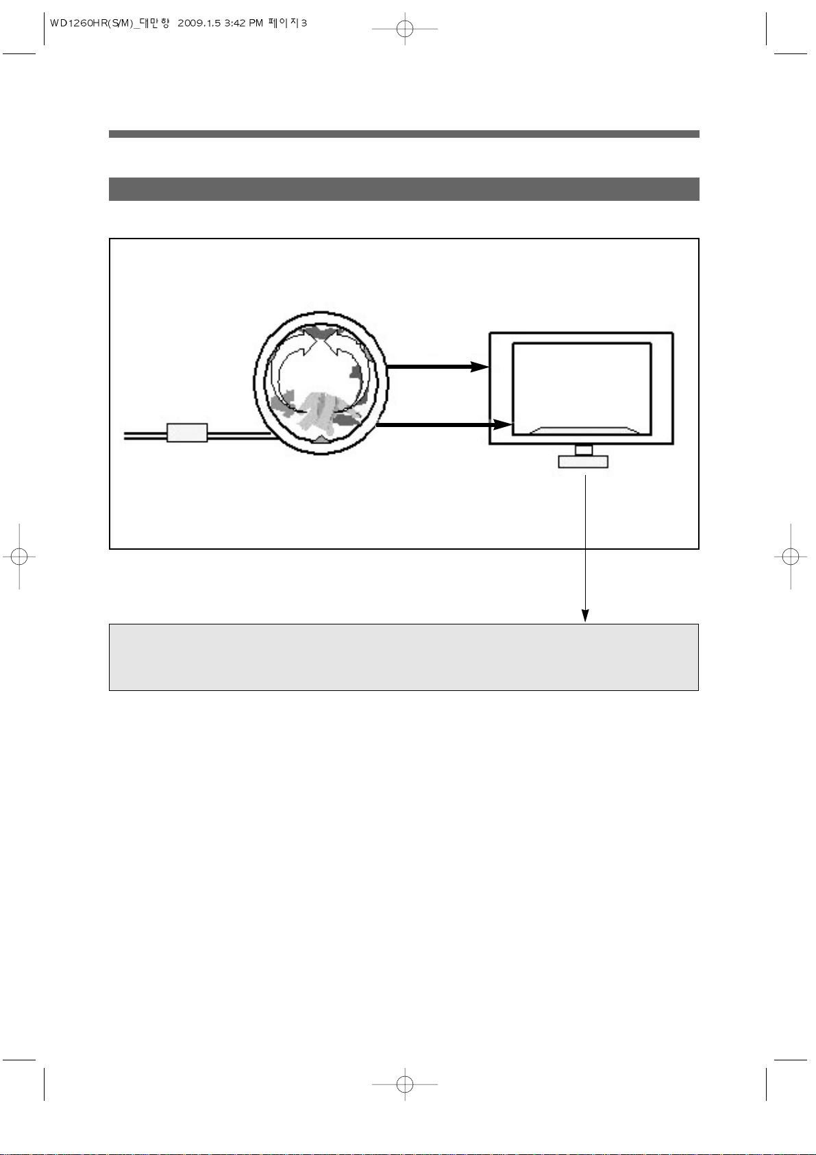
One of the famous washers in the globe which uses laundry falling energy.
1. WHA T IS DRUM ?
1. WHA T IS DRUM WASHER?
❖ The biggest capacity with compact size
❖ Environmently friendly washer with NANO technology
• Sterilizing up to 99.9%
❖ No damage and entanglement but excellent washability
❖ 4way savings-noise, vibration, washing times, energy
❖ Self-cleaning course of Drum
❖ Good washing performance with heating system
❖ Condensing dry system with saving energy
❖ Big door glass with easy laundry take-in/out
❖ The highest spin speed - 1200rpm
❖ Superior Interior Design
2. Sales point of our washer
Page 4
3
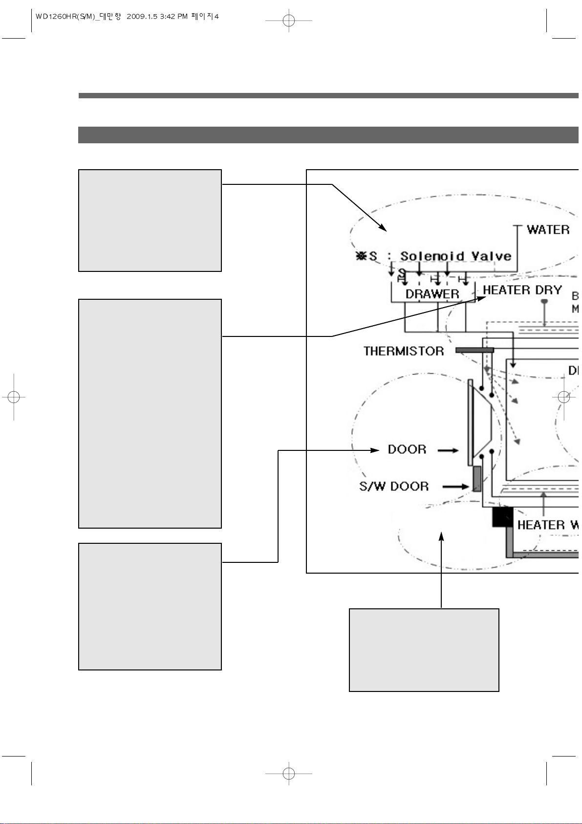
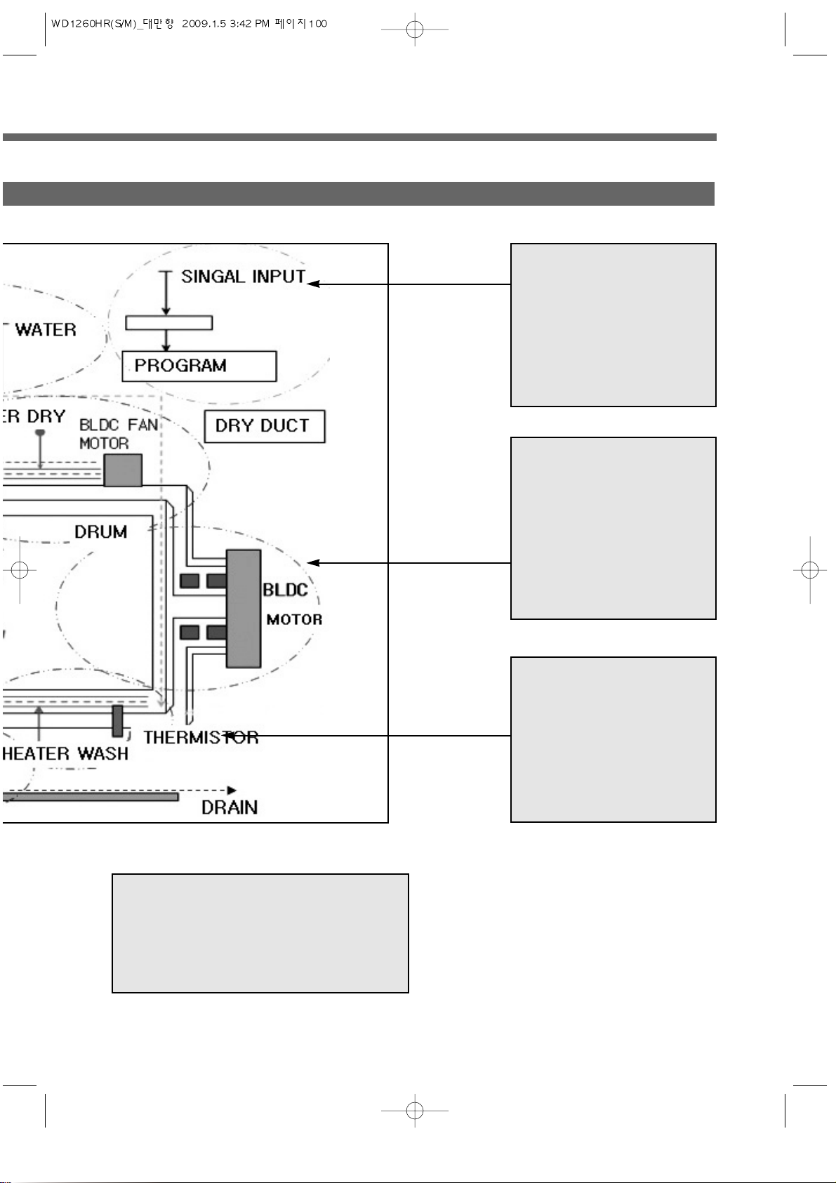
• DD CONTROL : DIRECT DRIVE SYSTEM
• BLDC MOTOR
3. THE DIRECT DRIVE SYSTEM OF DRUM WASHING MACHINE
TUB
DRUM
LIFTER
WASH
BLDC
DRAIN
PUMP
(MOTOR)
Page 5
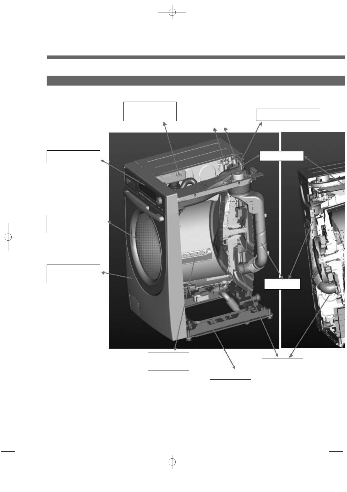
4. DRIVE SYSTEM
4
3. INLET PARTS
• COLD : 3-WAY
- COLD, PREWASH, DRY
• COLD : 2-WAY
- COLD, PREWASH
5. DOOR PARTS
• DOOR LOCK S/W
: ADDING CLOTHES
• LOCK HINGE
• DOOR AS : GLASS
• GASKET
7. DRAIN PARTS
• DRAIN PUMP(MOTOR)
• VALVE HOUSING
• DRAIN HOSE I
6. DRY PARTS
• HEATER DRY : OPTION
• BLOWER FAN
• FAN MOTOR : BLDC
• THERMISTOR
• THERMOSTAT
: FUSE, BI-METAL
• CONDENSING SYSTEM
• DRY FAN DRIVE
→GENERATION OF
HEATER’S HEAT
→TEMP. SENSOR
→110°C Off 100°C On :
OPTION
DRAIN PARTS
Page 6
4
1. CONTROLLER
• MAIN PCB
• FRONT PCB
• HARNESS
• NOISE FILTER
• POWER CORD : 15A
2. DRIVE PARTS
• BLDC MOTOR
• DRUM
• BEARING
• SPIDER/SHAFT
• TUB
• WEIGHT BALANCER
4. WASH HEATING
• WASH HEATER : OPTION
• THERMISTOR
• 40°C FIXED TEMP.
CONTROL : OPTION
• 60°C, 90°C BOIL
8. SUPPORTER
• BASE
• DAMPER AS : (Right)2(60N)/(Left)1(120N)
Spring : 4
Page 7
5
3. CABINET F ASSY
- DOOR AS
3. CABINET F ASSY
- CABINET F AS
1. PANEL F ASSY
2. INLET BOX AS
- INLET BOX
2. INLET BOX AS
- 3-WAY INLET VALVE
- 2-WAY INLET VALVE
- 1-WAY INLET VALVE
4. CABINET AS
7. DOCT AS
-DUCT AS
7. DOCT AS
-DUCT AS
5. BASE U AS
6. TUB ASSY
- LIFTER AS
6. TUB ASSY
5. FUNCTION
Page 8
5
8. PLATE T AS
6. TUB ASSY
- DRUM AS
5. BASE U AS
- PCB MAIN AS
6. TUB ASSY
- DRUM AS
(6-6)
(6-3)
(6-4)
(6-1)
(6-2)
(6-8)
(6-7)
(6-4)
(6-5)
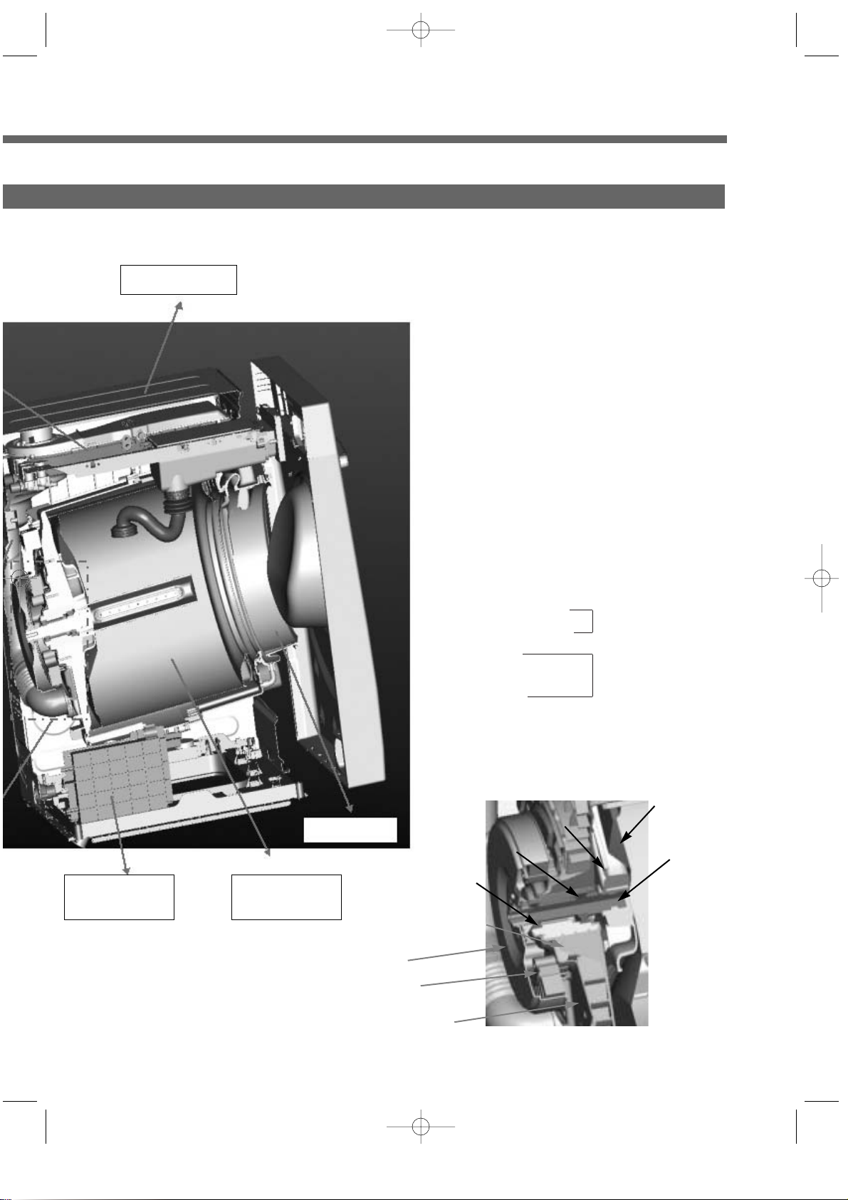
❋6. TUB ASSY - Parts For Driving
(6-1) BLDC ROTOR
BLDC MOTOR
(6-2) BLDC STATOR
(6-3) SHAFT
(6-4) BEARING Parts For Transmitting
(6-5) SPIDER
(6-6) DRUM
(6-7) TUB
(6-8) BASE
Page 9
6
DIMENSION(WxDxH) 630mm(W) x 755mm(D) x 950mm(H)
MACHINE WEIGHT 89 kg
WATER CONSUMPTION WASH 89 / DRY 28
WASHING CONSUMPTION 28
POWER SOURCE Option
POWER WASHING 1100W (Heating ) ~ 2400W : Option
CONSUMPTION DRY 1250W ~2400W : Option
WASHING 11 kg (Domestic)
CAPACITY SPIN 11 kg (Domestic)
DRY 6.5 kg (Domestic)
WASHING TYPE DRUM TYPE
DRY TYPE Digital condensing dry system
OPERATION WATER PRESSURE 29kPa ~ 784kPa(0.3kgf/cm
2
~8kgf/cm2)
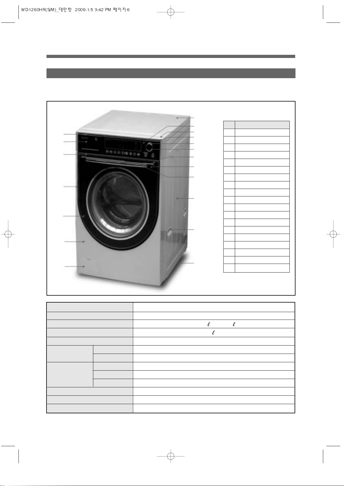
1 PREMIUM TYPE
2. DRUM WASHING SPECIFICATION OF MACHINE
1. EXTERIOR DIAGRAM
NO PARTS NAME
1 FRAME DOOR O
2 DOOR GLASS PLATE
3 DOOR GLASS BAND
4 HANDLE DOOR UPPER
5 HANDLE DOOR LOWER
6 HANDLE DOOR COVER
7 PANEL OUTER
8 PANEL INNER
9 PANEL PLATE
10 BUTTON DIAL OUT
11 BUTTON DIAL IN
12 CASE HANDLE
13 CASE HANDLE PLATE
14 CABINET F OUTER
15 COVER PUMP
16 PLATE T
17 CABINET
18 HANDLE CABINET
19 BASE UNDER
12
16
9
8
10
11
5
4
6
17
18
19
13
3
1
2
14
15
Page 10

7
DIMENSION(WxDxH) 630mm(W) x 755mm(D) x 950mm(H)
MACHINE WEIGHT 89 kg
WATER CONSUMPTION WASH 89 / DRY 28
WASHING CONSUMPTION 28
POWER SOURCE Option
POWER WASHING 1100W (Heating ) ~ 2400W : Option
CONSUMPTION DRY 1250W ~2400W : Option
WASHING 11 kg (Domestic)
CAPACITY SPIN 11 kg (Domestic)
DRY 6.5 kg (Domestic)
WASHING TYPE DRUM TYPE
DRY TYPE Digital condensing dry system
OPERATION WATER PRESSURE 29kPa ~ 784kPa(0.3kgf/cm
2
~8kgf/cm2)
2 LUXURY TYPE
1. EXTERIOR DIAGRAM
NO PARTS NAME
1 FRAME DOOR O
2 DOOR PLATE GUIDE
3 PROTECTOR GLASS
4 HANDLE DOOR UPPER
5 HANDLE DOOR LOWER
6 PANEL OUTER
7 PANEL INNER
8 BUTTON SELECT
9 BUTTON POWER
10 BUTTON DIAL OUT
11 BUTTON DIAL IN
12 CASE HANDLE
13 WINDOW DISPLAY
14 CABINET F OUTER
15 COVER PUMP
16 PLATE T
17 CABINET
18 HANDLE CABINET
19 BASE UNDER
12
16
7
6
10
11
9
5
4
17
18
19
13
8
1
3
14
15
Page 11
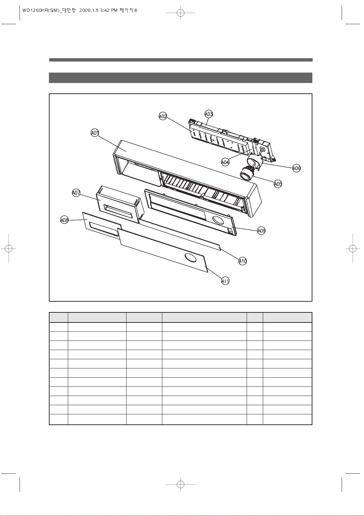
8
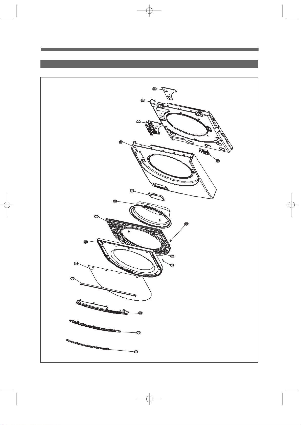
1. PLATE T, PANEL LOWER AS
3. PARTS LIST FOR EACH ASSY
No. PARTS NAME PARTS CODE DESCRIPTION Q’TY REMARK
1SBA0016824163 RETUO LENAP 10A
1
1
PR011E0032503163 MOTSUC DEL REDLOH 20A
A03 CASE PCB F 3611143600 HIPS
A04 PCB AS PRPSSW2D21 DWD-E110R FRONT PCB ASSY 1
A05 BUTTON DIAL AS 3616634700 130RP'S BUTTON DIAL AS 1
1 SPIH0012503163 LAID REDLOH 60A
1 SBA0083411163 ELDNAH ESAC 70A
1 CILYRCA0093411163 ETALP ELDNAH ESAC 80A
1 SBA0026824163 RENNI LENAP 90A
A10 PCB AS PRPSSW2D22 DWD-E110R TOUCH PCB ASSY 1
1 CILYRCA0036824163 ETALP LENAP 11A
Page 12
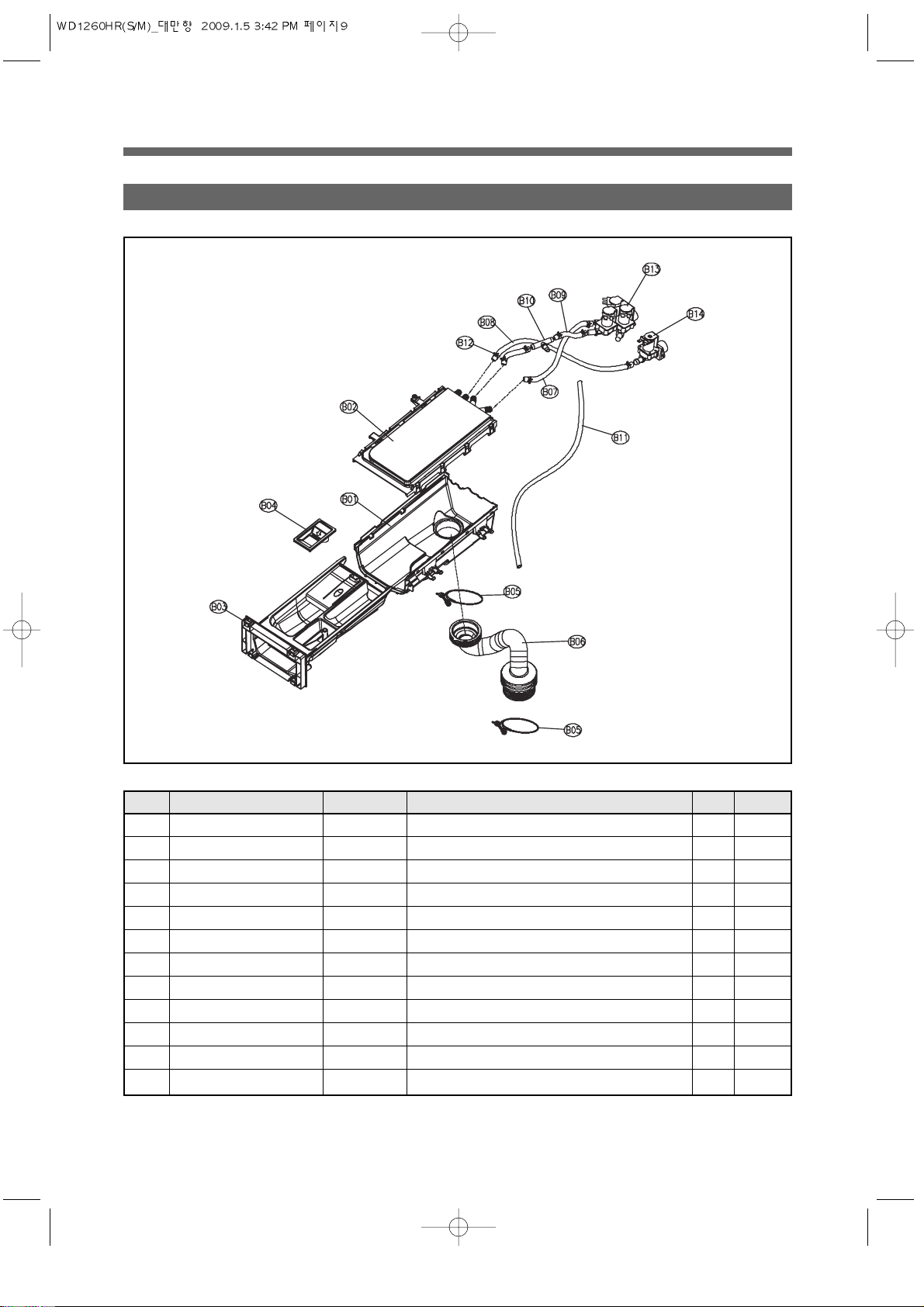
9
2. INLET BOX AS
YT’Q NOITPIRCSEDEDOC STRAP EMAN STRAP.oN
REMARK
1NR011B ,PP0026057163 XOBTELNI 10B
1 REDNU+POT ,PP0064018163 SA ELZZON 20B
1 PP0073411163 TNEGRETED ESAC 30B
1 PP0066190163 RENETFOS PAC 40B
B05 CLAMP AS 3611203200 ID=60, WIRE+GUIDE+BOLT+NUT 2
1 MDPE0001723163 TELNI ESOH 60B
82.0 5.41DO 5.9DI MDPE0090723163 70B
23.0 5.41DO 5.9DI MDPE0090723163 90B
1 PP0033144163 )TELNI ESOH(TNIOJ EPIP 01B
B11
3613270930 EPDM, ID8.5 OD12.5_SHOWER 0.62
HOSE WATER SUPPLY
HOSE WATER SUPPLY
HOSE WATER SUPPLY
8 T9.0 0.01=W 8.31=DI ,H0010085021163 ESOH PMALC 21B
B13 VALVE INLET AS 3615415070 100~130V,3WAY,RINSE,PP/BRACKET 1 COMBO
Page 13
10
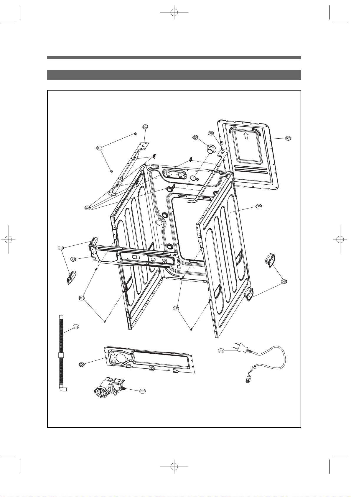
3. CABINET F ASSY
Page 14
11
No. PARTS NAME PARTS CODE DESCRIPTION Q’TY REMARK
1SBA0022180163 RETUO F TENIBAC 10C
1 T8.0 DCES0012180163 RENNI F TENIBAC 20C
1 R011E0053092163 SA ROOD EGNIH 30C
1 T0.2 GPS0049354163 TROPPUS EGNIH ETALP 40C
C05 SWITCH DOOR LOCK 3619047210 DL-S1.125V16A.BITRON 1
1 SBA0037022163 O ROOD EMARF 60C
1 SBA0047022163 I ROOD EMARF 70C
C08 PLATE PRINTING AS
36117ABJ20 Door Glass Plate+Silk Print As 1
C09 DOOR GLASS 361A110600 GLASS (DWD-100DR) 1
3 PR011E-DWD0048651163 ROOD NOIHSUC 01C
1 CDNZ0090013163 ROOD KOOH 11C
1 0.3D ,SUS0010028163 ELDNAH NIP 21C
100KBA71163 DNAB SSALG ROOD 31C
41C
10040162163 SA ROOD ELDNAH 51C
61C
1 SBA0067241163 PMUP REVOC 71C
Page 15
12
4. CABINET ASSY
Page 16
13
No. PARTS NAME PARTS CODE DESCRIPTION Q’TY REMARK
D01 NOZZLE AIR 3618103110 PP, DWD-100DR 1
D02 FRAME TOP R
D03 FRAME TOP L
D04 CABINET SUB AS 3610CABE40 E110R'S CABINET SUB AS 1
D05 COVER BACK AS 3611425510 COVER BACK + PAD CABINET AS 1
D06 STOPPER SPRING 3615202200 POM, DWD-100DR 4
D07 FIXTURE PLATE 3612008000 130RP,POM 4
D08 FRAME UPPER 3612207600 SBHG 1.2T 1
D09 FRAME LOWER
D10 HANDLE CABINET 3612608100 PP, DWD-100DR 4
D11 SPECIAL BOLT 3616029100 M4X12.5 MACHINE,DWD-100DR 4
D14 CORD POWER AS 3611339810 BSMI 2.0SQ 2C, 125V 13A 1 FT-2PIN
Page 17
14
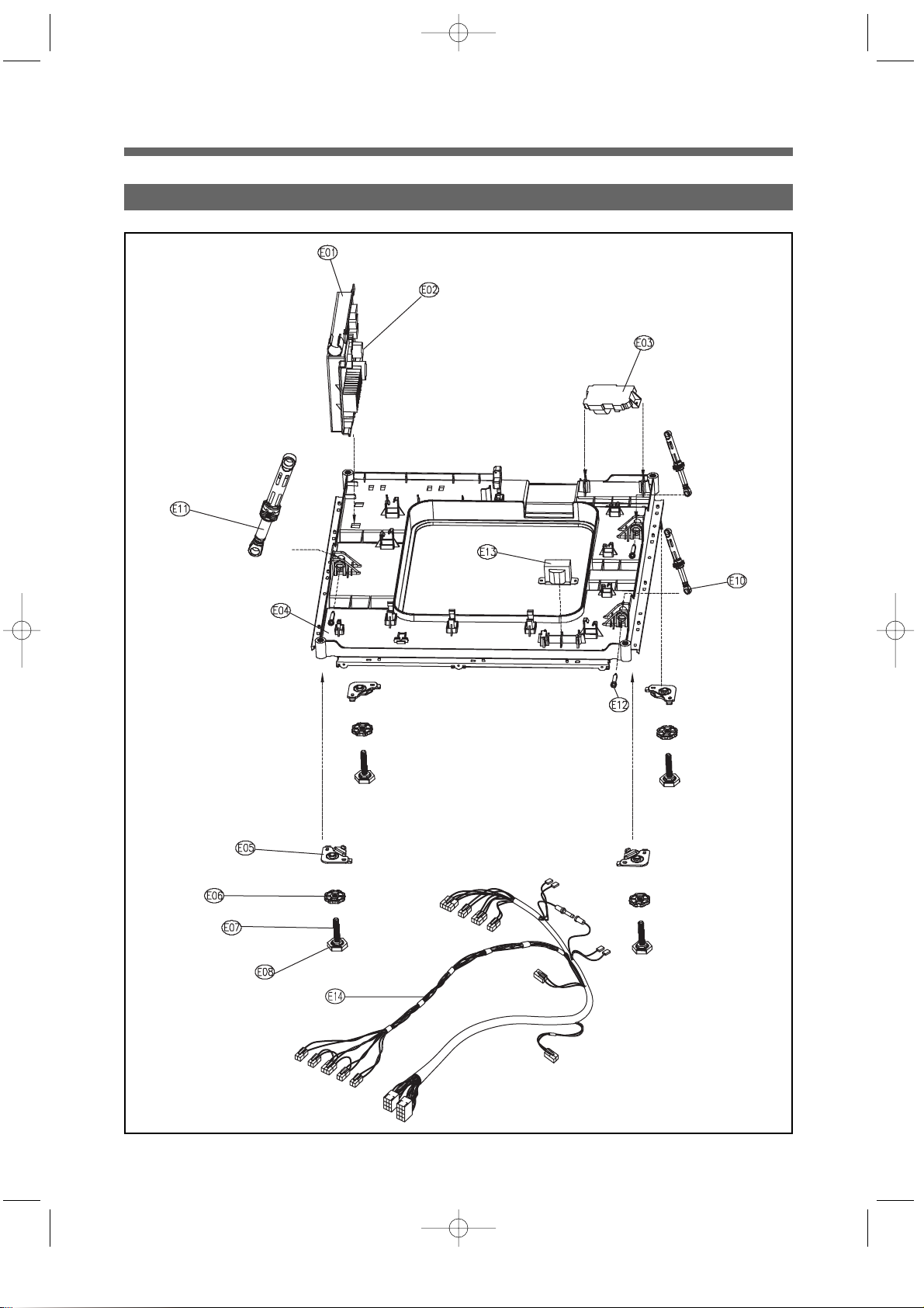
5. BASE U AS
Page 18

15
KRAMERYT’Q NOITPIRCSEDEDOC STRAP EMAN STRAP.oN
E01 CASE PCB MAIN 3611139300 HIPS
OBMOC1
1
V011 NAWIAT SEIRES E-DWD62D2WSSPRP )NIAM(SA BCP 20E
1 )HM01+474+174 RV ,V521 ESUF(V0010108091163 )1-91K IME(RETLIF TINU 30E
1 RD001-DWD ,PP0191930163 U ESAB40E
E05
E06
4 RD001-DWD0063077163 SA TSUJDA GEL
E07
E08
E10 DAMPER FRICTION 361A700130 60N AKS ST=170-260 DL=197.5 LOW NOISE 2
E11 DAMPER FRICTION 361A700120 120N AKS ST=170-260 DL=197.5 LOW NOISE 1
3 5.41=D SKA002007A163 NIP REPMAD21E
1 A8 ,)W(540-TR300J340G25 ROTCAER 31E
1 EVLAV ELGNIS ,YRD ,*11E02P6972163SA SSENRAH 41E
Page 19

16
6. TUB ASSY
Page 20

17
No. PARTS NAME PARTS CODE DESCRIPTION Q’TY REMARK
1R011E0028016163 SA L/R THGIEW RECNALAB10F
1 PP0094044163 TNIOJ EPIP20F
1 NFZM ,41ø0034021163 )EPIP ESOH( PMALC30F
1 MDPE0056623163 TNIOJ ESOH40F
OBMOC1 MDPE0070232163 TEKSAG 50F
1 PP0004018163 REWOHS ELZZON60F
1 TEKSAG0063021163 SA TEKSAG PMALC70F
29.20053115163 F NOISNEPSUS GNIRPS80F
3 5.41=D SKA002007A163 NIP REPMAD90F
F10
DAMPER FRICTION
361A700130 60N AKS ST=170-260 DL=197.5 LOW NOISE 2
1ESION WOL 5.791=LD 062-071=TS SKA N021021007A163 11F
1 MG0037HF PPRF1040288163 TNORF BUT21F
1T5.0 GK11103300716331F
1T5.0 GK111033007163SA BUS MURD41F
1T5.0 GK11103300716351F
F16 LIFTER AS 361A400350 DWD-A11*S,LIFT BODY+FILTER AS 3
1 GK11002003A163 SA REDIPS71F
1 MROF MDPE0011232163 BUT TEKSAG81F
1 32=TS ,V011-001 ,D02T7JH-VS00KAT69163 ROTOM NIARD 91F
1 MDPE0016623163 I NIARD ESOH 02F
1 PART+ESOH ,PR011101RAA0163 SA PART RIA12F
1 MG0037HF PPRF1050288163 RAER BUT22F
1 BAF Z60260013036163 RENNI GNIRAEB32F
GNISUOH GNIRAEB42F
1 GAF Z50260023036163 RETUO GNIRAEB52F
29.20063115163 R NOISNEPSUS GNIRPS62F
1 RD001-DWD ,MDPE0036623163RIA ESOH72F
1 54X044 T7.0 SUS0037002163 RETAEH ERUTXIF82F
1 400127A0R1 ,SUS ,WK1 ,V0110342082163HSAW RETAEH 92F
F30 UNIT BUBBLE PUMP 36189L4G00 110-130V, DBK-115DA, RP-CUSH 1
F32 UNIT STATOR BLDC 36189L4800 ø265X28H,36SLOT,2SENSOR,3254D02000 1
F33 UNIT ROTOR BLDC 36189L4900 MAGNET24,SERRATION,WR1238F001 1
Page 21

18
7. DUCT B AS+DUCT PIPE AS
Page 22

19
No. PARTS NAME PARTS CODE DESCRIPTION Q’TY REMARK
G01 UNIT FAN MOTOR 36189L3Z20 ISM-77806DWWA 24V,CW,8P,14W
G02 DUCT COVER 361A200400 AL, 2.5T, DWD-100DR
G03 DUCT B UPPER 361A201210 ALCOSTA 0.4T*228*449, 0.34KG
G04 CLAMP CORD 3611203350 L=94, W=5.6,A=8.0, LH-94
G05 FAN AS 3611885900 D133 FAN, GFPP30% <- NYLON66
G06
SPECIAL SCREW AS 3616030600 TAPTITE P, TRS4*16, WASHER
G07
1
1
1
1
1
1
EDV V052 A51 S821-FD C°821021008A163 ERUTAREPMET ESUF80G
G09
FRAME HEATER FRANGE
1RD001-DWD ,T2.1 GHBS0014022163
1
1
CDLA008102A163REWOL B TCUD01G
G11 PACKING THERMOSTAT 3614009900 SILICON, DWD-100DR1
G12 SWITCH THERMOSTAT 3619046500 ON120°C OFF150°C 230V 15A VDE 1
G13 HEATER DRY 3612801300 110V, 1.2KW, 10.080HM, 3.5W/SQ,1R1A034005 1
G14 THERMISTOR DRY 361AAAAC00 R40=26.065k?,R90=4.4278k? 1
1
G15 PACKING RUBBER 3614009800 SILICON, DWD-100DR1
2RD001-DWD ,RBN0082651163YRD NOIHSUC61G
1
1
5831=L,5ø ,PR011-DWD0280232163A LAES TEKSAG71G
G18 GASKET SEAL B 3612320810 EPDM FOAM, L=412, 4.9*4.4*4.8
10.1=T0092232163TELNI TEKSAG91G
1CDLA009102A163EDIUG TCUD02G
1GK11008002A163SA TCUD12G
2 TCUD0073021163)TCUD(SA PMALC22G
1MDPE0003046163TCUD SWOLLEB32G
64.0
4
5.41DO 5.9DI ,MDPE0090723163
P
YLPUS RETAW ESOH
42G
201=B ,6.0=T ,5.51=DI0083021163GNIRPS PMALC52G
Page 23

20
8. PLA TE TOP ASSY
No. PARTS NAME PARTS CODE DESCRIPTION Q’TY REMARK
H01 PLATE T 3614539500 SECD 1.2T 1
H02 LABEL CAUTION 3613553830 DRUM 11KG,DRY+WASH,KOR,PVC,95*143,SILK 2° 1
Page 24

21
4. SEQUENCE CHART OF PCB
1. SEQUENCE CHART
DIVISION Default Wash Temp
Small Middle Middle Small Middle Small Middle
Default Wash Temp
Sensing 20sec
Water Supply 2min ■
Pre. Wash 10min
8min
Drain 1min ■
Balancing Spin 2min ■
Mid.Spin 3min ■
Sensing 20sec ■■ ■■■■
Water Supply 2min ■■■■■■■
90min
80min
65min
Washing1 55min
(Heating) 50min
40min
35min
30min
25min
20min
Drain 1min ■■■■■■■
Balancing Spin 2min ■■■■■■■
Mid.Spin 3min ■■■■■■■
Water Supply 2min ■■■■■■■
Rinse 1 3min ■■■■■■■
Drain 1min ■■■■■■■
Balancing Spin 2min ■■■■■■■
Mid.Spin 3min ■■■■■■■
Water Supply 2min ■■■■■■■
Rinse 2 3min ■■■■■■■
Drain 1min ■ ■■■■
Balancing Spin 2min ■ ■■■■
Mid.Spin 3min ■ ■■■■
Water Supply 2min ■ ■■■■
Rinse 3 3min ■ ■■■■
Drain 1min ■■■■■■■
Balancing Spin 2min ■■■■■■■
7min
Main Spin 5min
3min
Crease care 60sec ■■■■■■■
END 10sec ■■■■■■■
Remain Time Display 1:25 1:30 1:54 2:06 2:16 1:41 1:51
NOTE
Pre.
Wash
W
a
s
h
i
n
g
R
i
n
s
e
S
p
i
n
END
Normal
40degree
40degree
95degree 60degree
Heavy Stain
White Eco-White
1. In the Heavy Stain Course, Prewash is included as Default.
2. Default Setting Times of Rinse in the Normal Course are two times.
3. According to Water Temperature, Wash Time is changed.
Cold - 30°C(5min)/30°C-40°C(5min)/40°C-60°C(15min)/60°C-95°C(25min)
47min.
52min.
Page 25

22
Wool Anti- Blanket Quick 30
Drum Drying Small Wash
Memory
Small Allergy Middle Middle High Small
Default Wash Temp Cold Cold 30°C Cold 40°C
Soak 30min ■
Water Supply 2min ■■■■■
40min
35min
30min
Washing 25min
20min
15min
10min
8min
Drain 1min ■■■■■
Balancing Spin 2min ■■■■■
Mid.Spin 3min ■■■■■
Water Supply 2min ■■■■■
Rinse 1 3min ■■■■■
Drain 1min ■■■■
Balancing Spin 2min ■■■■
Mid.Spin 3min ■■■■
Water Supply 2min ■■■■
Rinse 2 3min ■■■■
Drain 1min ■
Balancing Spin 2min ■
Mid.Spin 3min ■
Water Supply 2min ■
Rinse 3 3min ■
Drain 1min ■■■■■
Balancing Spin 2min ■■■■■
7min
Mid.Spin 5min
3min
Crease care 60sec ■
Dry 40min
30min ■
Cooling 5min ■■
END 10min ■■
Crease care 30min ■
Crease care 60sec ■■■■
END 10sec ■■■■
Remain Time Display
49 35 1:11 32 1:51 54
NOTE
W
a
s
h
i
n
g
R
i
n
s
e
S
p
i
n
D
R
Y
END
1. Anti-Allergy Course is for removing scent and sterilizing clothes by controlling temp.
about 70~80°C with heater dry on for 35 min.
DIVISION Default Wash Temp
Page 26

23
Eco-Steam Normal steam Strong Steam Cotton
Small Small Middle Middle
Default Wash Temp 40°C
Sensing 20sec ■■■■
Steam Water Supply 1min ■■■■
Steam Heating 20min ■■■■
15min
Steam Washing 10min
7min ■
Finishing Water Supply 1min ■■■■
30min
Finishing Washing 10min
5min ■■■■
Soak 30min
Water Supply 2min
30min
Washing 2 20min
15min
Drain 1min
Balancing Spin 2min
Mid.Spin 3min
Water Supply 2min
Rinse 1 3min
Drain 1min
Balancing Spin 2min
Mid.Spin 3min
Water Supply 2min
Rinse 2 3min
Drain 1min
Balancing Spin 2min ■■■■
7min
Main 5min
3min
Crease care 60sec ■■■■
END 10sec ■■■■
Remain Time Display
1:27 1:30 1:35 1:30
NOTE
S
t
e
a
m
W
a
s
h
i
n
g
R
i
n
s
e
S
p
i
n
END
1. Cotton Course is for all cooton clothes such as towel, diaper and the same course as
Normal Steam Course.
2. At the Steam Washing, Washing Time is 30min for Heavy Stain, and 20 min for the other
course.
3. Finishing Washing is the heating stroke to be reached up to Wash Temp, and if Wash
Temp. of Washing is 30-40°C, time is 5min, and if 60°C, time is 10min, if 95°C, time is
30min.
DIVISION
Default Wash Temp
Page 27

24
2-1. LOAD SENSING
1) Deciding the water level
1 Cotton, Whites, ECO-White course will be followed by this process.
2 Check the water level with dry laundry at the starting wash.
3 Check the water level by using motor output data during 20 sec, 65 rpm.
2) Deciding Spin Starting Step.
1 Check after finishing washing step with wet laundry.
2 Checking by using motor output data during 20 sec, 65 rpm.
3 The decided data is different depending on loading condition.
2-2. BALANCE SPIN
1) Motor running during balance spin.
1 Spreading the laundry : Rotating the same 45 rpm with left and right direction alternatively.
2 Attaching stop : Attaching the laundry to drum inside with constant speed.
3 Unbalance checking point : First step, check the U.B at 95 rpm, 160 rpm.
Second step, check the U.B at 95 rpm, 350 rpm.
Third step, at 300 rpm. if the unbalance data is over the criterion,
This process will be repeated.
4 Drain step : Drain at water around 160 rpm.
5 After drain, check the unbalance data again. This is so-called balance spin step.
2) Property of balance spin.
1 Conducting 10 times maximum.
2 If the washer can not pass balance spin step during 10 times, then water will be supplied.
3 If the washer can not pass 20 times of balance spin, UE error mode will be displayed on PCB.
2. Main function of PCB program
Page 28

25
2-3. DOOR S/W
1) The working principle of Door S/W
1 Door Locking
Bimetal on ( 3 sec) --> solenoid (supply 20msec pulse 2 times)
2 Door Unlocking
Bimetal off --> solenoid (supply 20msec pulse, until unlock)
3 After door locking, all parts can work normally.
4 After pressing power button, if the temperature of wash thermistor is over 50°C or the water level is
over the safety level, the door will be locked.
6 The door will be unlocked immediately after all processes are finished.
7 The door can be opened during processing if there is no problem to unlock.
Page 29

26
start / hold
door unlock button, 2sec.ON
Display <LOCK> off
Door open
drain
fan motor on/
cold water supply
water level is
less than safety level?
NO
NO
YES
YES
Temperature is
less than 50°C?
2) DOOR OPEN SYSTEM
1If add the laundry during washing, press the door unlock button.
2Door open sequence at abnormal condition.
Page 30

27
2-4. Child Lock
1 Press the “TEMP”. and “DRY” button simultaneously during processing.
2 Under the Child Lock function, only power button is working.
3 During Child Lock function, CHL will be displayed on PCB.
4 In order to unlock Child Lock mode, press "TEMP" and "DRY" simultaneously.
2-5. The sequence of drain
1 If the checking time to reset point is below 1 min, the remaining drain time is 30 sec.
2 If the checking time to reset point is over 1 min, the remaining drain time is 2 min.
3 If the checking time to reset point is over 10 min, OE singal will be appeared on PCB.
4 If the temperature is over 50°C, the water will be supplied to high water level, then the drain will
start.
Page 31

28
1. T esting Mode
PCB and other electronic parts will be tested without water supply whether they are normal or not.
1) Process : press power button --> press "SPIN" button 3 times with pressing "WASH" button --> 'L d' will be shown on LED -> Whenever pressing "TEMP" button 1 time, below process will be occurred.
L C (Lock Closed) --> F ( Fan Motor) ---> H (Hot V/V) --> C (Cold V/V) ->
P (prewashing V/V) -> d ( dry V/V) -> bb (bubble) -> dr (drain motor) ->
L O(Lock S/W Open)
2) More details
1When turn on 'LOCK' signal, all process is conducting normaly .
2When working starts, the PCB displays all the sensor conditions.
3In this case, BLDC Motor is not tested. In order to test it, select spin or rinse.
2. Continous testing mode
1) Process : after pressing "WASH", "RINSE", "SPIN" button simultaniously , press "POWER" button.
ALL LED On/Off 1 time --> L C (Lock Closed) ---> R (Motor right) --> L (Motor Left) --> F ( Fan Motor) ---> H
(Hot V/V) --> C (Cold V/V) --> b (pre-wash V/V)
--> d ( dry V/V) --> bb (bubble) --> h1 (HEATER WASH)--> h2(HEATER DRY) --> dr (DRAIN MOTOR On) ->L O(Lock S/W Open)
2) More tails
1LED test can be done with all LED On.
2All sensor conditions will be shown on PCB during processing.
3. Convenience service functions(test mode)
Page 32

29
4. ERROR DISPLAY
MESSAGE
ERROR CAUSE SOLUTION
The water tap is closed. Open the water tap.
The filter of the valve inlet is clogged. Clean the filter of the valve inlet.
The valve inlet is an inferior product or broke down. Change the valve inlet.
The water level sensor (sensor pressure) is an inferior product or Change the water level sensor
broke down. (sensor pressure).
The drain motor works during water supply. Change the drain motor.
The PCB ASS’Y does not check the water level. Change the PCB ASS’Y.
The drain hose is kinked or clogged. Clean and straighten the drain hose.
The drain motor is an inferior product. Change the drain motor.
The valve inlet works during drain. Change the valve inlet
The water level sensor is an inferior product . Change the water level sensor.
The PCB ASS’Y does not check the water level. Change the PCB ASS’Y.
The laundry is concentrated to one side of the drum Rearrange the laundry.
during spin.
The Start/Hold button is pressed while the door is opened. Close the door.
The switch door lock is an inferior product. Change the switch door lock.
The PCB ASS’Y does not check the door lock. Change the PCB ASS’Y.
The water is supplied continuously due to an inferior valve inlet. Change the valve inlet.
The valve inlet is normal, but the water level sensor Change the water level sensor
(sensor pressure) is inferior. (sensor pressure).
The drain motor dose not work. Change the drain motor.
(The drain motor is an inferior product or broke down.)
The fan motor does not work. Change the fan motor.
(The fan motor is an inferior product or broke down.)
The PCB ASS’Y does not control the fan motor. Check the connector or change the
PCB ASS’Y .
Water leaks from the tub or the hose drain. Check the leak of the tub or the hose drain.
Then change the tub or the hose drain.
The foreign matter is jammed in the drain bellows. Remove the foreign matter in the
(Non-pump model) drain bellows.
The laundry is jammed between the gasket and the drum. Rearrange the laundry.
The PCB ASS’Y is an inferior product. Change the PCB ASS’Y.
The laundry is jammed between the gasket and the drum. Rearrange the laundry.
The motor is an inferior product. Change the motor.
The PCB ASS’Y is an inferior product. Change the PCB ASS’Y.
The motor spins into an opposite direction. Change the PCB ASS’Y or the motor.
The motor hall IC is an inferior product or broke down. Change the motor hall IC or the motor.
The motor is not normally connected. Check the connector of the motor.
The motor does not work. Change the motor.
(The motor is an inferior product or broke down.)
The water level sensor is an inferior product. Change the water level sensor.
WATER INLET
ERROR
IE
DRAIN
ERROR
OE
UN-BALANCE
ERROR
UE
DOOR OPEN
ERROR
LE
OVERFLOW
ERROR
E2
FAN MOTOR
ERROR
E3
LEAKAGE
ERROR
E4
HIGH VOLTAGE
ERROR
E5
EMG ERROR
E6
DIRECTION
ERROR
E7
MOTOR ERROR
E8
SENSOR
PRESSURE ERROR
E9
Page 33

30
MESSAGE
ERROR CAUSE SOLUTION
The thermistor dry is an inferior product or broke down. Change the thermistor dry.
The thermistor dry is not connected normally. Check the connector of the thermistor dry.
The thermistor wash is an inferior product or broke down. Change the thermistor wash.
The thermistor wash is not connected normally. Check the connector of the thermistor wash.
The fan motor does not spin with the proper rpm. Change the fan motor.
(The fan motor is an inferior product or broke down.)
The thermistor dry is an inferior product or broke down. Change the thermistor dry.
The heater worked without the water in the tub. Check the water level.
The thermistor wash is an inferior product or broke down. Change the thermistor wash.
The water temp. is over 45°C in delicate & wool course. Change the thermistor wash.
The heater wash dose not work. Change the heater wash.
(The water temp. doesn't rise over 2°C during 15min.)
The heater dry dose not work. Change the heater dry.
(The water temp. doesn't rise over 3°C during 8min.)
The heater worked without the water in the tub. Check the water level and the heater wash.
The drain pump filter is clogged. Clean the drain pump filter.
The drain pump does not work during spin. Change the drain pump.
The large amount of detergent was used. Use the proper amount of detergent.
The drain hose is placed higher than 1m above the floor. Place the drain hose 1m below the floor
THERMISTOR
(TEMP. SENSOR)
DRY ERROR
H1
THERMISTOR
WASH ERROR
THERMISTOR DRY
OVERHEATING
ERROR
H2
THERMISTOR WASH
OVERHEATING
ERROR
H3
WATER TEMP.
ERROR
HEATER WASH
ERROR
HEATER DRY
ERROR
PUMP
FILTER
ERROR
HEATER WASH
OVERHEATING
ERROR
H4
H5
H6
H7
H8
PFE
Page 34

31
5. TROUBLE SHOOTING
1) VAL VE INLET
TROUBLE SITUATION CAUSE CHECK POINT SOLUTION
PCB
ERROR MODE
WATER IS
SUPPLIED
WATER
SUPPLY
IS NOT
STOPPED
Etc
NO WATER
SUPPLY WITH
"BUZZ" SOUND
NO WATER
SUPPLY
WITH SILENCE
THE WATER
SUPPLY START
WHEN POWER
"ON"
THE WATER
SUPPLY START
WHEN POWER
"OFF"
water leakage to the
side
closed water tap
coil short
alien materal jammed
alien material inside
inlet valve
unfixing connector
coil short
harness short
pressure s/w broken
pressure hose broken
inlet valve broken
inlet valve poorly
assembled
Open the water tap
Clean the filter
Change the Inlet-
Valve
The contact of the
Connector
Change the Inlet-
Valve
Change the Sensor
Pressure
Change the bad
parts
Change the Inlet-
Valve
Change the Inlet-
Valve
"IE"
"IE"
"IE"
"IE"
"IE"
"IE"
"IE"
"E2"
"E2"
-
-
check the water tap opened
check the resistance 4320~5280Ω
check the filter
–
check the connector
check the resistance 4320~5280Ω
check the connector
check the pressure switch
check the hose torn or twisted
–
check the leakage of inlet valve
Checking method of coil resistance, harness, connector.
MAIN PCB
WASH VALVE(GREEN) :
COMMON(BLUE)/RESISTANCE TEST
PRE-WASH VALVE(RED) :
COMMON(BLUE)/RESISTANCE TEST
DRY VALVE(YELLOW) :
COMMON(BLUE)/RESISTANCE TEST
COMMON(BLUE)
"8P" WHITE
CONNECTOR
* "IE" ERROR : lack of water supply
Page 35

32
2) PRESSURE SWITCH
TROUBLE SITUATION CAUSE CHECK POINT SOLUTION
PCB
ERROR MODE
continuously
water supply
"E9"
ERROR
inlet valve is normal,
but continuous water
supply
water level frequence
below 15kHz or over
30kHz
bellows problem
hose problem
clogged hose
connector slipped out
pressure switch broken
connector short
change the
pressure switch
change the hose
change the hose
remove the alien
reconnecting
change the
pressure switch
"E2"
"E2"
"E2"
"E2"
"E9"
"E9"
"E9"
frequency Check : refer to below
frequency Check : refer to below
check the fine hole
check the hose condition
check the connector condition
frequency Check : refer to below
connector broken
Checking method of coil registance, harness, connector.
* E2 : overflow error ;Water level is higher than overflow level because of continuous water supply.
E9 : Pressure switch trouble, the frequency is less than 15kHz or more than 30kHz in the processing.
■Checking method of the Frequency
1 Power ON
2 First, press the “DRY” button 3 times with pressing
the “WASH” button. The frequency of Air status will
be appeared.
ex) 623 ➝ 26.23kHz.
3 Press “TEMP” button
1 time: water supply
2 times: stop the water supply
3 times: start the drain
4 times: stop the drain
5 times: return to Air status mode
GROUND(GRAY)
OUTPUT
SIGNAL(WHITE)
INPUT SIGNAL
(PINK)
"12P" WHITE CONNECTOR
Page 36

33
3) DOOR LOCK SWITCH
Failure
Details Cause Diagnosis of Failure Solution
PCB
Status
ERROR MODE
"
Tick
"
Sound
"LE" Error
DOOR not
open
Tick Sound happens
"LE" with tick sound
"LE" without tick sound
Power Failure/Forced
Power Off during
operation
Power on state
ETC
Normal Sound
Connector slipped out
DOOR closed loosely
Failure of DOOR HOOK
CATCH CAM broken
Connector slipped out
Terminal slipped out
Solenoid Coil
Disconnection
Water remained in tub
hot temp. in tub
Follow below process
During operation, "Power Failure" or "Forced Power S/W OFF" causes door not to be opened until
maximum 5 minutes pass.
Assemble Connector
Close Door securely
Replace DOOR AS
Replace DOOR S/W
Assemble Connector
Insert Receptacle no.2
or no.3
Replace DOOR S/W
After draining water,
open the door
-
"LE"
"LE"
"LE"
"LE"
"LE"
"LE"
"LE"
-
check the joining status of
connector by eye
-
Tick sound happen
check the joining status of
connector by eye
Refer to below checking
method.
Refer to below checking
method.
Check whether the water
level is over safety level.
When Door is locked/unlocked, this Solenoid Working
sound is heard.
Prevent the burn due to hot temp. after dry.
Checking Method of wiring/coil disconnection, connector slipping out on PCB board : Operate with the Door lock
switch connected
1) CLASS
1. Replacing method of DOOR LOCK SWITCH
1) Open DOOR, disassemble CLAMP SPRING for fixing gasket
2) Disassemble GASKET
3) Disassemble two screws for DOOR LOCK S/W
4) Disassemble DOOR LOCK S/W
5) Assemble in the reverse order
Page 37

34
2. Checking method of DOOR LOCK SWITCH
3. Checking method of DOOR LOCK SWITCH
2 3 4 5
(No no.1)
Between No. 3 & No.4
: if 156 ~ 234Ω, it is normal
Between Viloet and Blue wire
: If 156 ~ 234Ω, it is normal
PIN
array
Page 38

35
4) HEATER
Failure
Cause Diagnosis of Failure Solution
PCB
Status
Error Mode
Can not
heat
water
Overheat
water
Can not
dry
Wiring Disconnection
Heater Wash
Disconnection
Connector/Terminal
Seclusion
Heater Wash/Thermistor
Wash Poor
Heater Wash/Thermistor
Wash Poor
Wiring Disconnection
Heater Dry Disconnection
Fuse Temp.
Connector/Terminal
Slipped out
Operation Trouble of FAN
MOTOR
Heater Wash/Thermistor
Fault of Thermistor (Dry)
Connecting the
disconnecting point
Replacing Heater Wash
terminal/connector tightly
Connecting
Replacing temp. sensor
Replacing Heater Wash
Inserting terminal/connector
Replacing Fuse Temp.
tightly
Connecting
Re-connecting
Replacing Fan motor
Re-assemble after
disassembling
Replace Thermistor
Check whether disconnected or not : See Fig. A
Check whether disconnected or not : if normal, the
resistance between two ends is 23.3~25.7Ω.
Check whether disconnected or not : See Fig. A
Measure the resistance of two ends of the sensor : if
11.981KΩat R25, it is mormal
Measure the resistance of two ends of the sensor : if
11.981KΩat R25, it is mormal
Check whether disconnected or not : See Fig. B
Check whether disconnected or not : if normal, the
resistance between two ends is 22.3~24.7Ω.
Shipped out
Check whether disconnected or not : See Fig. B
Excessive Noise : Restraint/Failure of Fan Motor
Fan slipped out : MOTOR is operating, but there is
rotating sound.
Measure the resistance of two ends of the sensor : if
26.065KΩ, it is mormal
"H6"
"H6"
"H6"
"H2"
"H2" or "H4"
"H7"
"H7"
"H7"
"H7"
"H7" or "E3"
"H7"
"H1"
Checking Method of wiring/coil disconnection, connector slipping out on PCB board : Operate with the heater connected
* Inspect Wiring/Heater
Wash Disconnection :
Check the current and
resistance of two
terminals
3P Connector
orange wire
1P Connector
Blue Wire
* Inspect
Wiring/Heater Dry
Disconnection :
Check the current
and resistance of two
terminals
3P Connector
Red Wire
1P Connecor
Blue Wire
[Figure A] [Figure B]
Page 39

36
* Replaceing method of Heater and Temp. Sensor
1. Disassemble Connector
3. Replace heater & sensor
2. Disassemble EARTH and NUT for fixing heater
4. Assemble in the reverse order. Be sure to assemble in the
order : Nut for heater-Nut for EARTH.
* ERROR MODE
1. "H1" : Thermistor Dry OPEN/SHORT
2. "H2" : Thermister Wash OPEN/SHORT
3. "H3" : Dry Overheating(Sensing Temp. is over 125°C)
4. "H4" : Wash Overheating(Sensing Temp. is over 95°C)
5. "H5" : Wash Overheating
(In Wool, Lingerie courses sensing temp. is over 45°C)
6. "H6" : Abnormal condition of Heater Wash
(when the temp. increase at 10 minutes after heater operation is under 10°C)
7. "H7" : Abnormal condition of Heater Dry(when the temp. increase at 10 minutes after heater operation is under 10°C)
8. "H8" : Heater Wash Overheating
(when the temp. increase within 30sec after heater operation is over 5°C without water)
9. "E3" : FAN MOTOR Broken(no signal from HALL IC)
I
C
D
F
E
H
B
A
G
Division Parts Name
A DUCT COVER
BFAN MOTOR
C HEATER DRY
D DUCT B LOWER
E THERMOSTAT(Bimetal)
F THERMISTOR (Temperature Sensor)
G DUCT B UPPER
H FAN AS
I FUSE TEMPERATURE
Page 40

37
1) BLDC MOTOR
2) Driving mechanism of BLDC MOTOR
BLDC MOTOR
Magnetic density flow of BLDC Motor
Sequence diagram of BLDC MOTOR
5) MOTOR
Rotor
Insulator
Core
Insulator
electromagnet
generating high power by rotator
(a permanent magnet) and stator
(multiple coils)
Page 41

38
1) DRY SYSTEM
6) DRY SYSTEM(OPTION)
E
J
C
D
G
F
I
B
A
H
Division Parts Name
A DUCT COVER
B FAN MOTOR
C HEATER DRY
D DUCT B LOWER
E VALVE INLET(DRY)
F THERMOSTAT(Bimetal)
G THERMISTOR(Temperature Sensor)
H DUCT B UPPER
I FAN AS
J FUSE TEMPERATURE
Page 42

39
2) DRY FUNCTION DIAGRAM
3) TEMP-TIME GRAPH DURING DRY CYCLE
While rotating DRUM, DRY HEATER applice heat to air and FAN blows it into DRUM evaporating water in the laundry.
• Evaporated water is sucked into CONDENSING DUCT, and condensed in DUCT contacting WATER SUPPLY (condensed water
is extracted through DRAIN HOUSING).
• Dry function is performed by continuous repetition of evaporating and condensing circulation as above.
DRY DUCT
T : Thermistor
(CONTROL
HEATER’S
TEMPERATURE )
HEATER
FAN MOTOR
CONDENSING
DUCT
DRUM
DRAIN
HOUSING
"#
$%&'()
*+
()
,-./!
01"#
2)
T
WATER SUPPLY
INSIDE TEMPERATURE
OF DRUM
TIME
DRYING PROCESS
ZONE
TEMP.
PRE HEATING
ZONE
Page 43

40
4) DRY COURSE
COURSE DRY COURSE
LOW TEMP.
Heater control temperature is 60°C On/70°C Off
Drying Time is 120/180min according to Load Sensing Data
IRON
Heater control temperature is 60°C On/70°C Off, with good condition for ironing
Drying Time is 70/130min according to Load Sensing Data
Cupboard
Heater control temperature is 100°C On/110°C Off, drying time is 166 min
Drying Time is 150/210min according to Load Sensing Data
STRONG
Heater control temperature is 100°C On/110°C Off, drying time is 216 min
Drying Time is 210/270min according to Load Sensing Data
SELECTING TIME Heater control temperature is 100°C On/110°C Off, customer can select the drying time
1Hr, 2Hr, 3Hr. out of 1:00, 2:00, 3:00
In order to check the drying temperature during process going on : --> press the "DRY" button, the display shows as below.
UPPER LED:
Temperature for DRY
The current temperature is 98°C
LOWER LED:
Temperature for WASH
REMAIN TIME
"#$%
Page 44

41
5) TROUBLE SHOOTING OF DRY SYSTEM
✦
HEA TER DR Y
Function : heating the air during dry
• FAILURE MODE : * "H7" - The air cannot be heated to 10°C during 2 min.
• CHECKING METHOD : * Check the resistance of heater coil and replace with new one.
✦
Thermistor
Function : sensing the air temperature.
• FAILURE MODE : * The air cannot be heated even though water is supplied.
* "H1" - shot or cut-off
* "H3" - air temp. is reached over 150°C
• CHECKING METHOD : * Check the resistance of thermistor, replace with new one.
✦
FUSE TEMPERA TURE
function : protecting from the fire hazard or overheating, if the temp., rises over 128°C, power supply will be cut-off.
• Pictures
• FAILURE MODE : Dry is not performed.
• CHECKING METHOD : Check if fuse is short, and replace with new one.
FIXED BY
WASHER
+SCREW
Page 45

42
✦
SWITCH THERMOST A T(BIMETAL)
function : control the duct temperature, if the temp reached over 150°C, all power supply will be cut. and if the temp go down
120°C the power will be ON.
protecting overheating by cutting off heater power supply if the temperature rises over 150°C, and reoperating heater
by connecting heater power supply if the temperature falls under 120°C.
• OPERATING TEMPERATURE • PICTURE
✦
UNIT F AN MOTOR
function : circulating the inside air during dry process.
• SPEC • PICTURE
• FAILURE MODE : * E3 shown : FAN MOTOR cannot work.
• CHECKING METHOD : Check the FAN MOTOR is short, and replace with new one.
OPEN TEMPERATURE(OFF) 150°C ±5°C
CLOSE TEMPERATURE(ON) 120°C ± 5°C
ITEMS SPEC
RATING VOLTAGE 24V
RPM
MOTOR 3700 ± 10%
DUCT FAN AS 1900 ± 10%
ROTAING DIRECTION CW
Page 46

43
6) LACK OF DRY PERFORMANCE
• Situation : after drying, the clothes still get wet.
cause) ☞The laurdry amount is more than the recommendation capacity 7.0kg.
☞Condensing cold water is not supplied.
☞Clogging Bellows Duct results in poor air circulation.
checking method)
• Situation after drying, the clothes was soaked and hot.
cause) ☞ The dry is done from bad spin performance because of unbalance.
☞no spin was done before the dry had started.
• Situation : PCB shows "H1" or "H3".
cause) ☞Thermistor is broken.
☞Thermistor is short or cut-off.
countermeasures) ☞replace the Thermistor.
part name checking point checking results jurge repair method
BELLOWS
DUCT
VALVE INLET
+Condensing
HOSE
clogging
bellows duct
no water supply
from inlet valve
heater was
overheated
owing to poor air
circulation
VALVE INLET
connector slipped
out
VALVE INLET
broken
ill-connection of
condensing hose to
duct pipe
clean the bellow
duct
connect normally
replace valve inlet
connect normally
BELLOW
DUCT
VALVE INLET
CONDENSING
HOSE
Page 47

44
• Situation : PCB shows "H7".
cause) ☛ Dry heater is cut-off.
☛ Fuse temp. is cut-off.
repaire method) ☛ replace the Dry heater.
☛ replace the Fuse temp.
checking point part name checking results repaire method
HEATER
SENSOR TEMP.
FUSE TEMP.
dry Heater is short or cut-off.
Thermistor is short or cut-off.
FUSE TEMPERATURE is cut-off.
replace the
dry Heater.
replace the
Thermistor.
replace the
FUSE
TEMPERATURE.
THERMISTOR
HEATER DRY
FUSE
TEMPERATURE
Page 48

45
• situation : PCB shows "E3".
cause) ☞FAN MOTOR can not work.
countermeasures) ☞Replace the Fan Motor.
part name checking results repair method disassemble process of Fan Motor
FAN MOTOR fan motor failure replace
fan motor
1Disassemble Duct Cover As from Duct B As
(Screw 4EA)
2Disassemble FAN AS From Duct Cover As
(Fixed by 8mm NUT)
3Disassemble the FAN MOTOR(SCREW 3EA)
parts Control time
MOTOR 10 sec On, 10sec Off
DRAIN MOTOR Continous working
FAN MOTOR Continous working
DRY HEATER 100°C On, 110°C Off
INLET VALVE 5sec On, 20sec Off
Remarks) control times of each parts during dry process
DUCT COVER AS
Fixed By 8mm NUT
Page 49

46
DOUBLE VALVE, BUBBLE
DOUBLE VALVE, N/BUBBLE
6. WIRING DIAGRAM
(OPTION)
(OPTION)
DRAIN PUMP
Or
DRAIN MOTOR
(OPTION)
DRAIN PUMP
Or
DRAIN MOTOR
(OPTION)
Page 50

47
7. TROUBLE SHOOTING REGARDING DRAIN
❑Checking Methods
• Situation : * "OE" is shown on PCB.
* Not finishing drain during 10 min.
* The water level can not reach to RESET POINT during 10 min of drain.
Checking Methods
* Check the hose drain O condition; twisted or frozen.
* Check the hose drain O condition, blocked.
* DRAIN MOTOR is broken.
Replacing methods
* replace HOSE DRAIN O
* clean the inside of Filter.
* replace DRAIN MOTOR
Page 51

48
8. INSTALLATION GUIDE
1. PARTS & CONFIGURATION
2. INSTALLATION PROCESS
1Remove the FIXTURE UP/DOWN AS
2Insert CAP HOLDER(4EA) after removing FIXTURE UP/DOWN AS.
Removal Method Remarks
☞Disassemble the FIXTURE UP/DOWN AS by
turning CCW direction.
☞Please keep FIXTURE UP/DOWN AS for later use.
☞When fixing FIXTURE UP/DOWN AS, turn it CW
direction.
PARTS NAME
FIXTURE UP/DOWN AS
UNIT SERVICE WRENCH
LEG ADJUST AS
REMARKS
SPECIAL SCREW UP
: L= 109mm
SPECIAL SCREW DOWN
:L=145mm
1Use this part to remove
FIXTURE UP/ DOWN.
2Adjust leg with this part.
FIGURES
SPECIAL SCREW
UP
FIXTURE UP FIXTURE
DOWN
FOOT
FIXTURE
LEG
CAP HOLDER
SPECIAL
SCREW
DOWN
Page 52

49
3Please install the DRUM W ASHING MACHINE properly on even and hard floor as below .
4Adjust the level of washer using LEG ADJUSTAS.
Adjusting Method Remarks
☞If turned CW, the LEG ADJUST AS moves the
washer upward.
☞If turned CCW, the LEG ADJUST AS moves the
washer downward.
5After adjusting level, fix SPECIAL BOL T.
Adjusting Method Remarks
✰ Please fix the SPECIAL BOLT by rotating it CCW
in order to prevent washer vibration.
Page 53

50
9. ATTENTION POINT WITH SERVICING
No Item Part Name Checking Point
1 Replacing Thermistor Thermistor Dry Keep the Packing from seperating (Hold Packing when replacing)
Dry Keep the Packing from folding
2 Replacing Duct B As DUCT B AS & Check the sealing between Duct Pipe & Duct B AS
& Duct Pipe DUCT PIPE
3 Replacing & Inlet Valve Use only screw M4*8 for fixing Inlet Valve
Repairing Inlet Valve
4 Replacing Hose Drain Hose Drain Keep the sealing condition of Tub O tightly
5 Replacing HOSE HOSE A,B,C Check the assembling order between INLET BOX & Hose A,C :
A,B,C Pre Wash-Cold
6 Replacing Heater Wash Unfastening the nut for fixing earth first then unfasten
Heater Wash the nut for fixing heater
At assembling the heater dry, check if the assembling condition between
fixture heater is tight.(little gap on left & right)
At fastening the nut for fixing the heater wash, keep the protrusion length
of bolt to 10~12mm.
(if under 10mm, water can leak, and if over 12mm, fixture heater can
deform)
7 Replacing Thermistor Wash Unfasten the Nut for fixing heater, replace the thermistor, and
“Thermistor Wash” fasten the nut for fixing heater
8 Assembling Hinge Door
At fastening screw for fixing Door AS, be careful so that scratching at
“Hinge Door” the related parts does not happen
: If the scratching happens, it is possible to be claimed about
appearance damage
9 (Dis)assembling Door As Be careful about the up/down direction of Door Glass : Keep the
“Door AS” indication point of the part code downward.
10 (Dis)assembling MOTOR AS To avoid the injury on the hand, grip the rim of the rotor
“Motor AS” At initiating the assembling operation of the stator, grip the
stator and fasten the screw; at unfastening the screw, grip the stator so
that it does not fall.
Page 54

S/M NO. :
DAEWOO ELECTRONICS CORP.
1-2, Jeo-dong 1(il)-ga, Jung-gu, Seoul, Korea
C.P.O. BOX 8003 SEOUL, KOREA
TELEX: DWELEC K28177-8
CABLE: “DAEWOOELEC”
PRINTED DATE: Dec. 2008
Page 55

334455446677!
!
88--99::;;443399<<!!447788==
>? @A( BCD
EFG HIJK LM
ABOUT THIS MANUAL
ABOUT THIS MANUAL
NOPQR S
T=!/6,9U 8V9,WXYZ;8[!
[=!/6,9U \,WXE]^-_5`/abcde
fgX]]Z=WX=Xh
Wi
Xi
Rjhi
Li
ki
lmn
oo pp
/9/6!fgq!_rkLsa
tuv
345467
N O
wxg
;9Uq Yh]V]EE]!T:yq Yh]VhYZZ
]Z=WX=XhVzG<!{<!Ws<!Zs<!|s<!W]s<!WWs<!WXs<!Whs<!WLs<!Wks<!WEs<
WYs<!WZs<!W|s<!X]s!gjb!}~ WEs
]|=]W=]kVXs<!Zs<!|s<!WWs<!Whs<!Wks<!WYs<!W|s!gjb!}~ Zs
 Loading...