

Page 1

D1146
Primary filter:clean at every 5,000km,change at every 15,000km there
Change at every 20,000km.
166Page
Valve clearance Adjust at end of first 1,000km and every 20,000km there after. 171 Page
Air cleaner Clean at every 4,000km, change at every 12,000km there after. 176 Page
Transmission oil Change at end of first 5,000km and every 20,000km there after. 178 Page
Rear axle oil Change at end of first 5,000km and every 20,000km there after. 179 Page
Power steering oil Change at end of first 1,000km and every 24,000km there after. 180 Page
Power steering filter Change at end of first 1,000km and every 24,000km there after. 182 Page
IMPORTANT SERVICE ACTIVITIES
ҧAny failure resulting from a lack of normal maintenance as the maintenance service chart in this manual is not covered
by warranty.
CHECK ITEMS CHECK AND SERVICE INTERVALS PAGE
Engine oil 163 Page
Change : At end of first 1,000km,
long distance : every 30,000km
short distance : every 20,000km
D1146Ti
DE08TiS
DE12/T/Ti/TiS
Fuel filter
D1146
D1146Ti
DE12
DE12T
DE12Ti
Primary filter : clean at every 5,000km,
change at every 15,000km there after.
secondary filter : change at every 5,000km.
Engine oil filter Change with engine oil 164Page
DE08TiS
DE12TiS
Change : At end of first 1,000km,
High-speed, long distance : every 15,000km
In city, short distance : every 10,000km
Page 2

This manual has been prepared to acquaint you with the operation and maintenance of your DAEWOO
BUSES and the provide important safety information. We urge you to read it carefully and follow the
recommendations to help assure the most enjoyable, safe and troublefree operation of your vehicle.
When it comes to service, remember that your DAEWOO dealer knows your vehicle best and is
interested in your complete satisfaction.
We would like to take this opportunity to thank you for choosing a DAEWOO product and assure
you of our continuing interest in your motoring pleasure and satisfaction.
This manual should be considered as a permanent part of your vehicle, and must remain with the
vehicle at the time of resale.
All information, illustrations and specifications contained in this manual are based on the latest product
information available at time of publication.
The right is reserved to make changes at any time without notice.
FOREWORD
Page 3

1
1. IMPORTANT INFORMATIONŋŋŋŋŋŋŋŋŋŋŋŋŋŋŋŋŋŋŋŋŋŋŋŋŋŋŋŋŋŋŋŋŋŋŋŋŋŋŋŋŋŋŋŋŋŋŋŋŋŋŋŋŋŋŋŋŋŋŋŋŋŋŋŋŋŋŋŋŋŋŋŋŋŋŋŋŋŋŋŋŋŋŋŋŋŋŋ 2
2. OPERATION AND CARE OF NEW VEHICLE
ŋŋŋŋŋŋŋŋŋŋŋŋŋŋŋŋŋŋŋŋŋŋŋŋŋŋŋŋŋŋŋŋŋŋŋŋŋŋŋŋŋŋŋŋŋŋŋŋŋŋŋŋŋŋŋŋŋŋŋŋŋŋŋŋŋŋ 4
3. GETTING ON AND OFF, DRIVER’S SEAT AND BELT
ŋŋŋŋŋŋŋŋŋŋŋŋŋŋŋŋŋŋŋŋŋŋŋŋŋŋŋŋŋŋŋŋŋŋŋŋŋŋŋŋŋŋŋŋŋŋŋŋŋŋŋŋŋŋ 6
4. INSTRUMENT, SWITCHES AND CONTROLS
ŋŋŋŋŋŋŋŋŋŋŋŋŋŋŋŋŋŋŋŋŋŋŋŋŋŋŋŋŋŋŋŋŋŋŋŋŋŋŋŋŋŋŋŋŋŋŋŋŋŋŋŋŋŋŋŋŋŋŋŋŋŋŋŋŋ 14
5. DRIVING
ŋŋŋŋŋŋŋŋŋŋŋŋŋŋŋŋŋŋŋŋŋŋŋŋŋŋŋŋŋŋŋŋŋŋŋŋŋŋŋŋŋŋŋŋŋŋŋŋŋŋŋŋŋŋŋŋŋŋŋŋŋŋŋŋŋŋŋŋŋŋŋŋŋŋŋŋŋŋŋŋŋŋŋŋŋŋŋŋŋŋŋŋŋŋŋŋŋŋŋŋŋŋŋŋŋŋŋŋ 135
6. INSPECTION AND MAINTENANCE
ŋŋŋŋŋŋŋŋŋŋŋŋŋŋŋŋŋŋŋŋŋŋŋŋŋŋŋŋŋŋŋŋŋŋŋŋŋŋŋŋŋŋŋŋŋŋŋŋŋŋŋŋŋŋŋŋŋŋŋŋŋŋŋŋŋŋŋŋŋŋŋŋŋŋŋŋ 162
7. LUBRICATION
ŋŋŋŋŋŋŋŋŋŋŋŋŋŋŋŋŋŋŋŋŋŋŋŋŋŋŋŋŋŋŋŋŋŋŋŋŋŋŋŋŋŋŋŋŋŋŋŋŋŋŋŋŋŋŋŋŋŋŋŋŋŋŋŋŋŋŋŋŋŋŋŋŋŋŋŋŋŋŋŋŋŋŋŋŋŋŋŋŋŋŋŋŋŋŋŋŋŋŋŋŋ 213
8. SCHEDULED MAINTENANCE SERVICE
ŋŋŋŋŋŋŋŋŋŋŋŋŋŋŋŋŋŋŋŋŋŋŋŋŋŋŋŋŋŋŋŋŋŋŋŋŋŋŋŋŋŋŋŋŋŋŋŋŋŋŋŋŋŋŋŋŋŋŋŋŋŋŋŋŋŋŋŋŋŋ 221
9. TROUBLESHOOTING
ŋŋŋŋŋŋŋŋŋŋŋŋŋŋŋŋŋŋŋŋŋŋŋŋŋŋŋŋŋŋŋŋŋŋŋŋŋŋŋŋŋŋŋŋŋŋŋŋŋŋŋŋŋŋŋŋŋŋŋŋŋŋŋŋŋŋŋŋŋŋŋŋŋŋŋŋŋŋŋŋŋŋŋŋŋŋŋŋŋŋŋŋŋ 225
10. MAIN DATA AND SPECIFICATION
ŋŋŋŋŋŋŋŋŋŋŋŋŋŋŋŋŋŋŋŋŋŋŋŋŋŋŋŋŋŋŋŋŋŋŋŋŋŋŋŋŋŋŋŋŋŋŋŋŋŋŋŋŋŋŋŋŋŋŋŋŋŋŋŋŋŋŋŋŋŋŋŋŋŋŋŋ 234
11. BODY DIMENSION
ŋŋŋŋŋŋŋŋŋŋŋŋŋŋŋŋŋŋŋŋŋŋŋŋŋŋŋŋŋŋŋŋŋŋŋŋŋŋŋŋŋŋŋŋŋŋŋŋŋŋŋŋŋŋŋŋŋŋŋŋŋŋŋŋŋŋŋŋŋŋŋŋŋŋŋŋŋŋŋŋŋŋŋŋŋŋŋŋŋŋŋŋŋŋŋ 253
TABLE OF CONTENTS
Page 4
2
IMPORTANT INFORMATION
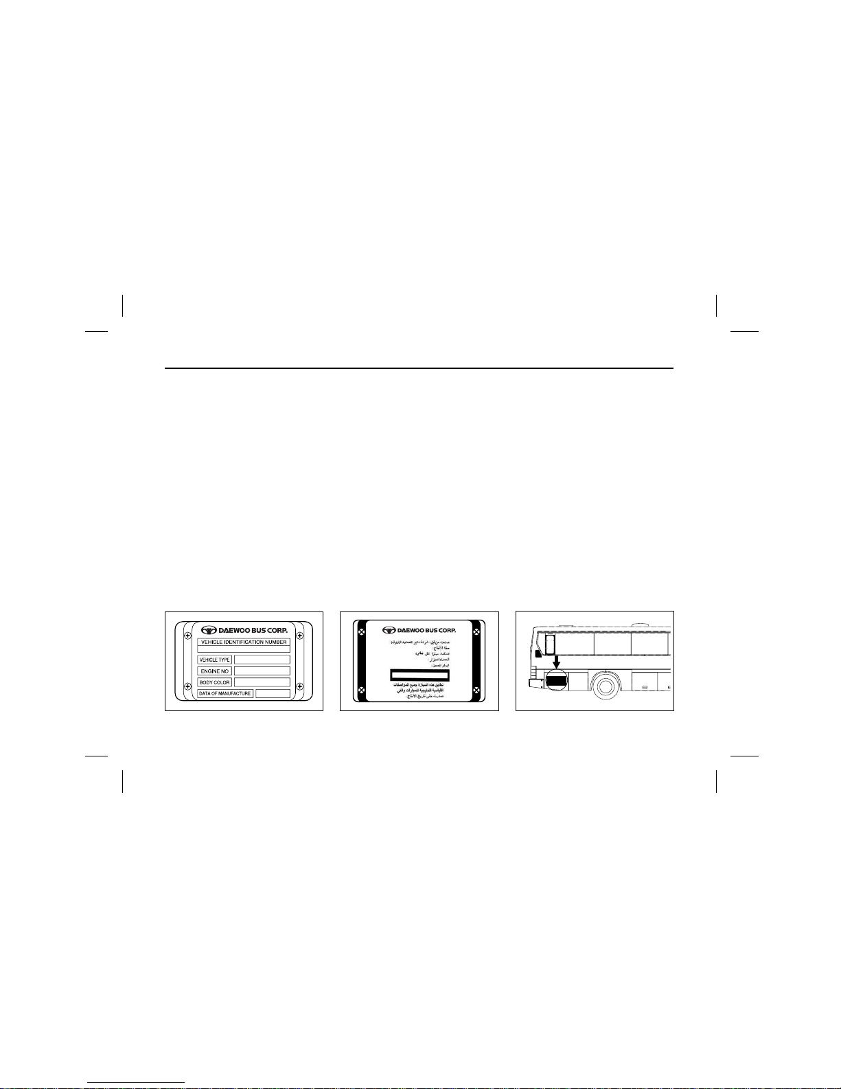
LOCATION OF ENGINE NUMBER AND CHASSIS NUMBER
It is advisable to keep note of the engine number and chassis number as they are required when contacting your dealer for repair services and parts order.
V.I.N plate
V.I.N(Vehicle identification Number)
plate is attached to the inner panel
above the front door.
Type A : Applicable for vehicles in
all countries except GCC
members.
V.I.N plate
V.I.N(Vehicle identification Number)
plate is attached to the inner panel
above the front door.
Type B : Applicable for vehicles in
GCC members.
Chassis number
The chassis number is stamped on
the upper face of the chassis frame
within the engine compartment.
Page 5
3
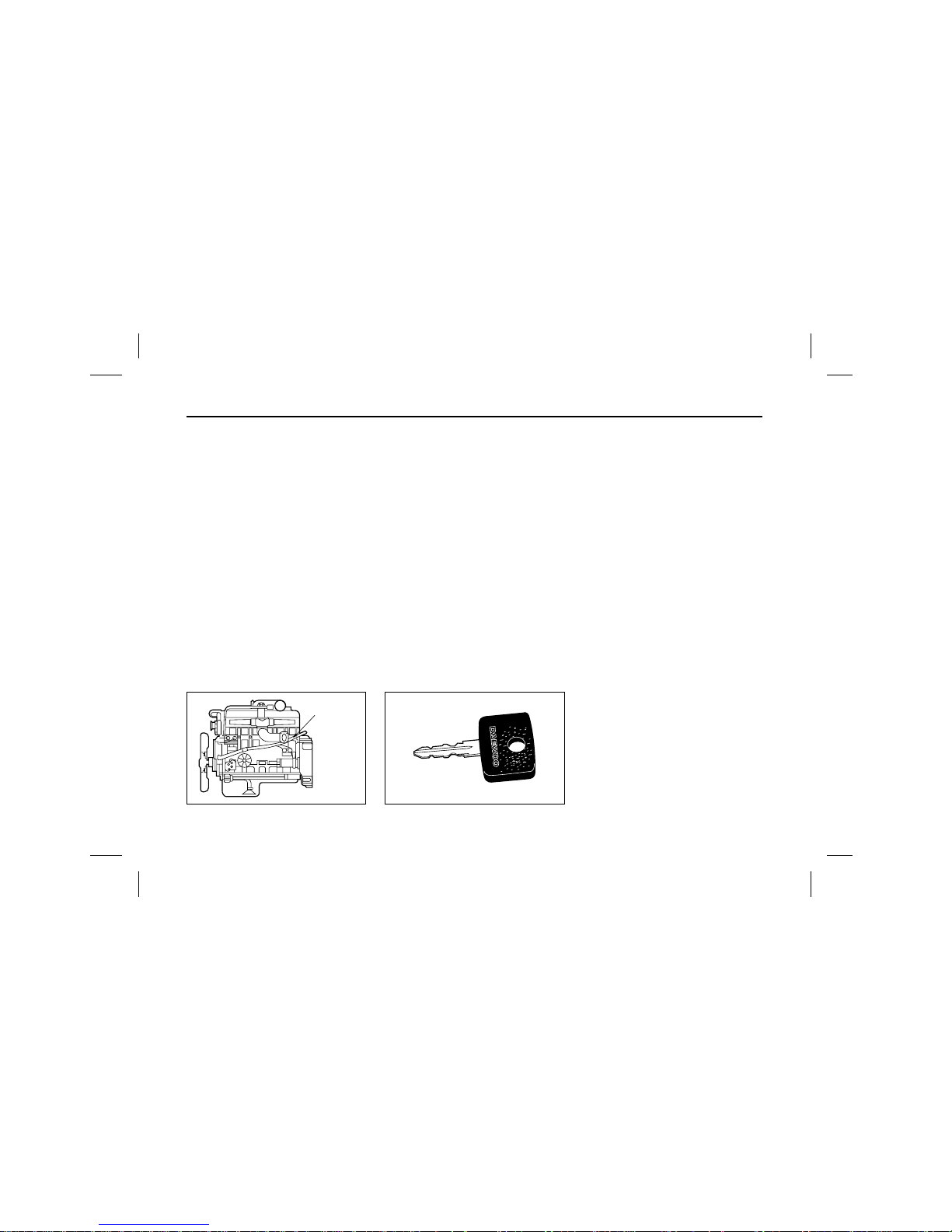
Engine number Key
There are three types of key for the
bus ;
• Engine starting
• Mechanical locking for entrance
door (OPTION)
• Doors
– Entrance door operating
– Luggage doors (OPTION)
– Rear engine door (OPTION)
– Side engine doors (OPTION)
– Battery inspection door (OPTION)
–
Fuel tank inspection door (OPTION)
– Fuel inlet flap door (OPTION)
The keys are not interchangeable, but
door lock keys are interchangeable.
The code number of each key is
stamped on the key.
Record the key number and keep it
in a safe place.
In the event that the original key is
lost, duplicating can be done using
the key code information.
Engine No.
1378
Page 6

4
OPERATION AND CARE OF NEW VEHICLE
It is important to observe the following precautions as operation and care
of the vehicle, particularly during the
break–in period have a strong influence over the performance and service life of the vehicle.
1. Start and let the engine idle until
it becomes thoroughly warmed up
and coolant temperature increases
beyond 50°C (or 125°F) before
starting off.
2. Avoid racing the engine, abrupt
starts and hard stops.
3. Avoid over loading the vehicle during and after the break–in period.
Over loading
Over loading not only shortens the
service life of your vehicle but also
create serious potential safety hazards.
The weight of payload must be limited within the GVW rating and distributed over the front and rear axles so
as not to exceed the axle capacities.
Refer to “MAIN DATA AND SPECIFICATION” for GVW and Axle capacity.
Maintenance
In order to maintain safe and dependable vehicle operation, inspection and
adjustment should be performed as
outlined in “INSPECTION AND MAINTENANCE”.
Your DAEWOO dealer is willing to
perform regular maintenance operation on your vehicle.
Page 7

5
Engine oil change
Change engine oil filter catridge to new one at the
same time with engine oil.
Maximum engine speed
During the initial milage(Break–in period : 2,000km),
confine engine speed to 70% of the maximum and
scan the tachometer as you drive to prevent engine
over–running.
After the break–in period, increase the engine speed
gradually to complete running–in of the vital parts.
Engine Model Change Interval
D1146
At end of first 1,000km
D1146Ti
High–speed, long distance :
DE12Ti every 15,000km
DE12Ti In city, short distance :
DE12Ti every 10,000km
DE08TiS
At end of first 1,000Km
Long distance : every 30,000km
DE12TiS
short distance : every 20,000km
Page 8
6
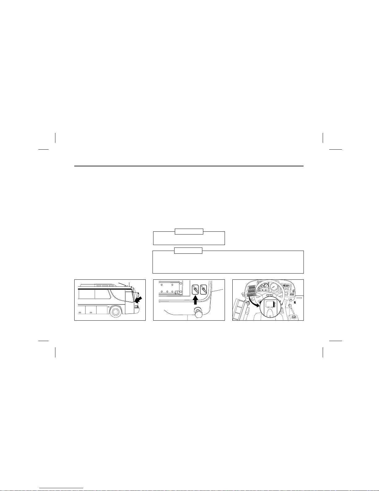
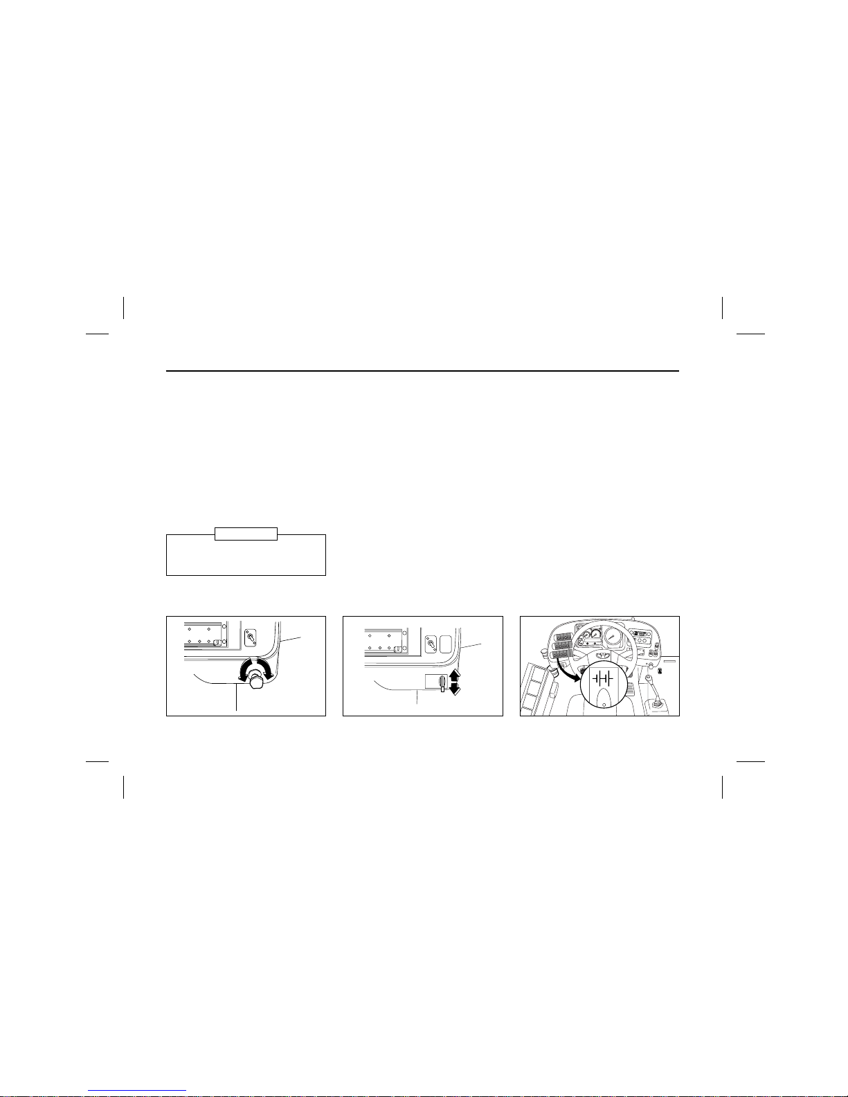
GETTING ON AND OFF, DRIVER’S SEAT AND BELT
DOOR OPENING AND CLOSING
(Applicable for vehicles in all
entrance door with mechanical key)
When opening the front door to get
in, first unlock the mechanical key on
the entrance door and operate the
entrance key on the right side of the
front middle panel.
When closing the front door to get
off, open the front door by operating
the door control switch and get off.
In the outside of bus, close the door
with the key and look the mechanical
key on the entrance door not to be
opened in case of air leaking.
(Applicable for vehicles in all
entrance door except mechanical key)
When opening the front door to get
in, operate the entrance key on the
right side of the froot middle panel.
When closing the front door to get
off, open the front door by operating
the door control switch and get off.
In the outside of bus, close the door
with the key.
I
D
L
I
N
G
H
.
.
L
Before operating entrance key, unlock
mechanical key on door frame.
NOTICE
When opening front entrance door for a long time, setting emergency valve
at manual position and put control switch in close position. When returning
to automatic condition, putting control switch and door in same condition
and set emergency valve at automatic position.
CAUTION
(Type A : Toggle switch) (Type B : One touch switch)
Page 9
7
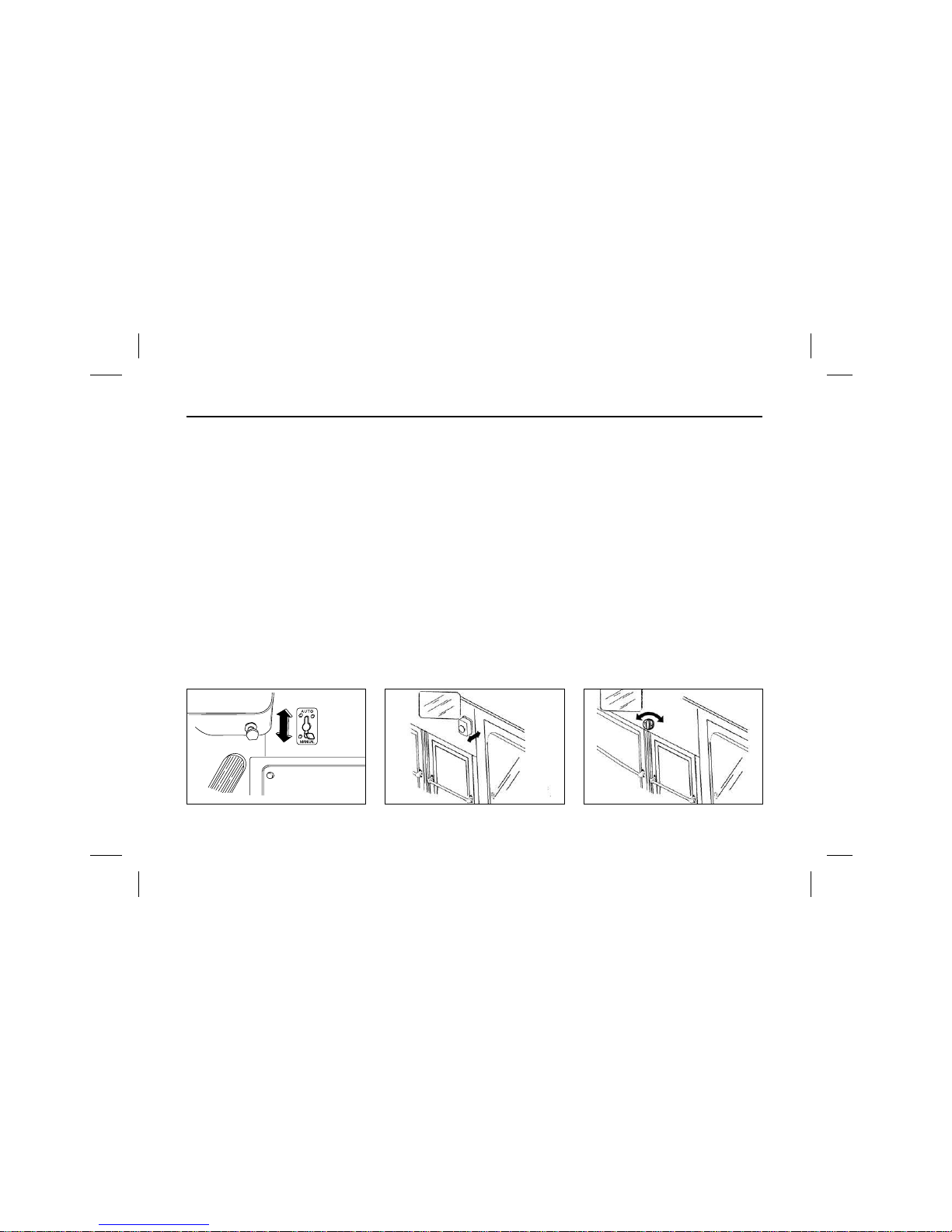
MANUAL OPENING AND
CLOSING
Type A : Select type
As setting the “Auto–Manual” change
lever installed right, lower inner side
of front panel(beside of driver’s right
leg), the door can be opened and
closed by hands.
Type B :
Push/Pull or rotary type (OPTION)
As setting the "Auto-Manual" change
knobs are installed two types. One of
the types installed inner upper panel
the entrance door operated by air.
Other installed outer mid panel on left
side of door operated by electric push
button. the door can be opened and
closed by hands.
I
D
L
I
N
G
H
.
.
L
(Push/Pull type) (Rotary type)
Page 10
8
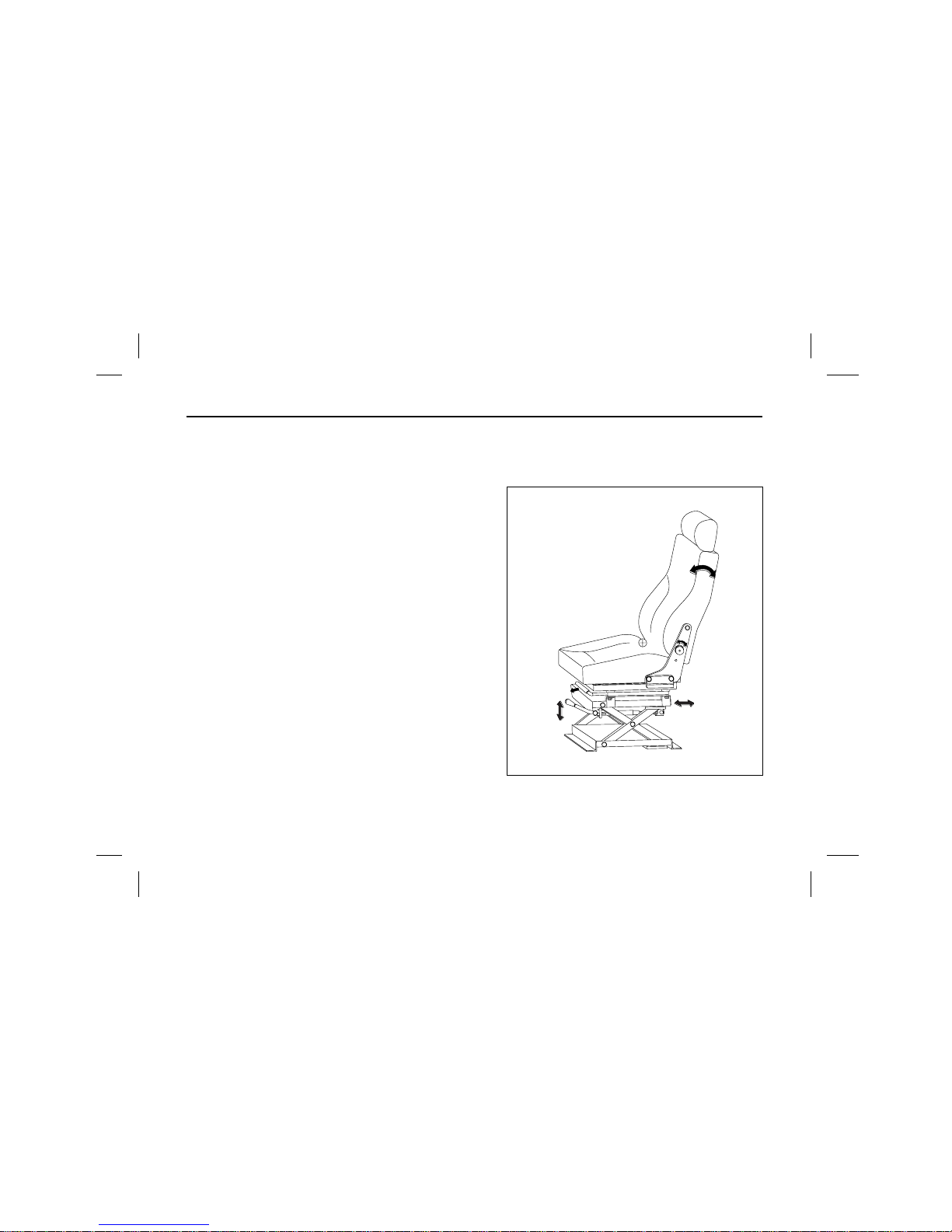
Adjustment of Fixed type (S-104H) (BM090, BS090)
1. Back angle adjustment
To adjust the seat back, turn No. 1 handle, and lean
backwards and foreward until desired angle is
achieved.
2. Slide adjustment
To move the seat forward and backward.
Pull No. 2 lever, forward and slide the seat.
3. Height (Tilting) adjustment
Desired the seal height can be achieved by puling
No. 3 lever upward and downward.
2
1
2
3
1
DRIVER’S SEAT AND BELT
Page 11
9
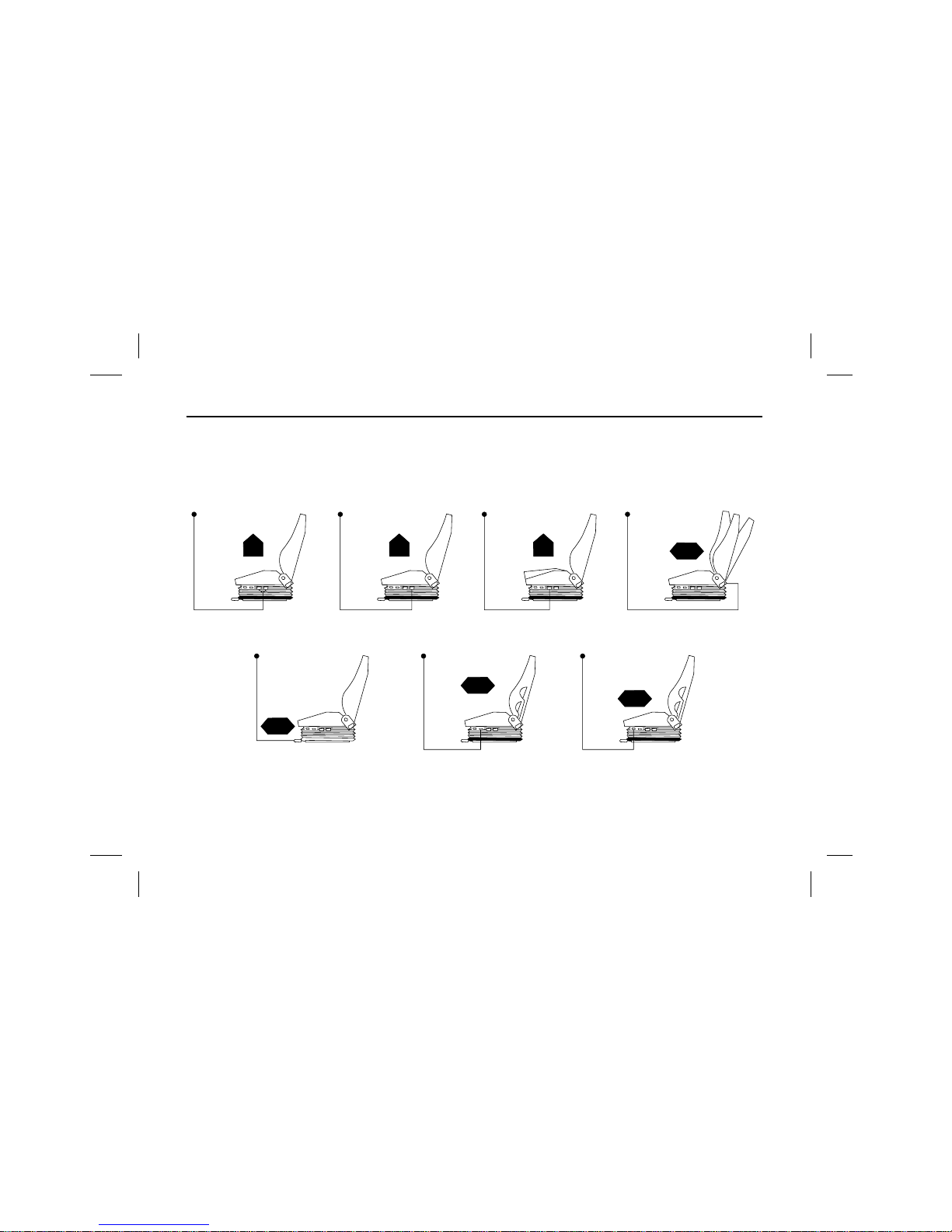
How to use non suspension seat
Semi suspension seat can be infinitly adjusted to suit the weight of the driver.
Height Adjustment
Back Angle
Slide Adjustment
Page 12
10
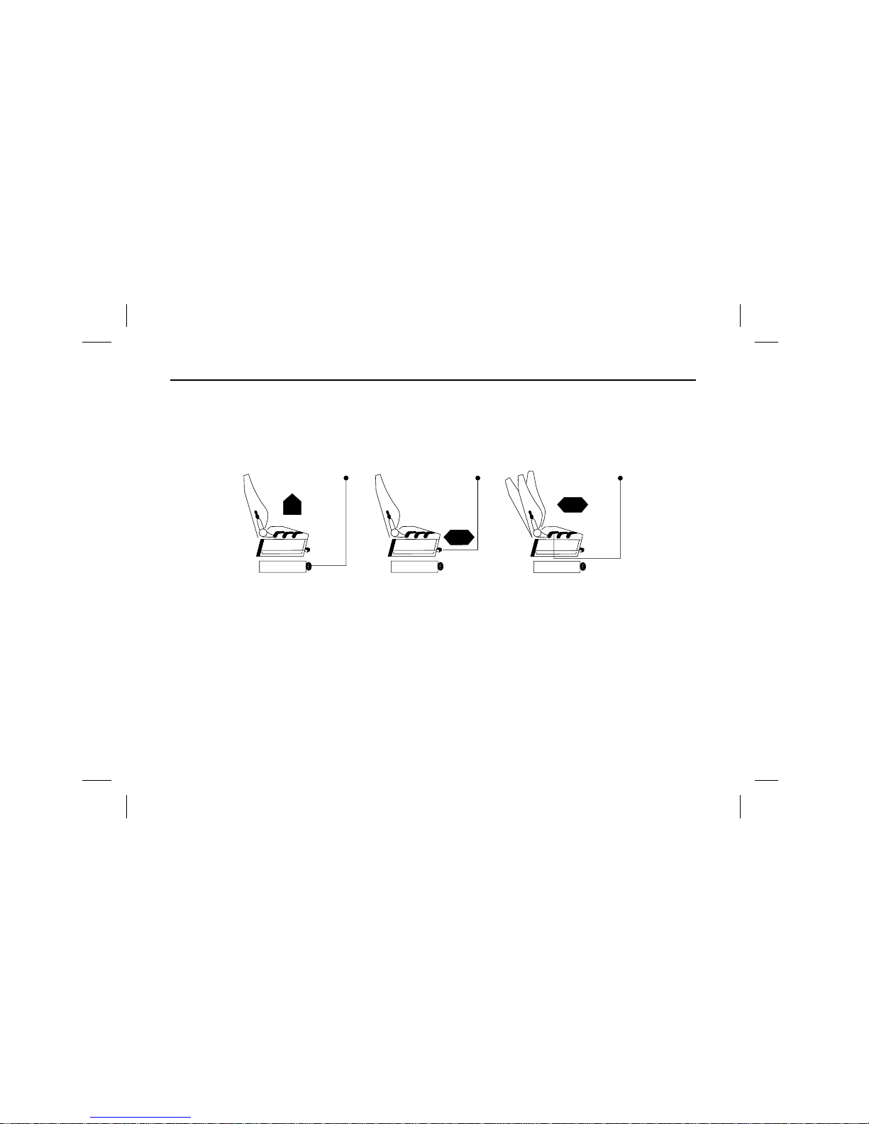
Adjustment of Air suspension type driver’s
seat (S-110A) (BS106, BH113/115/120E, BV120)
1. Slide adjustment
To move the seat forward or rearward, pull No. 1 lever
upwards and the slide the seat.
2. Back angle adjustment
To adjust the seat back, pull No. 2 lever and lean
backwards or forewards until the desired angle is
achieved.
3. Height and slope adjustment
Desired seat height can be achieved by pulling No. 3
lever.
4. Upper lumbar support air cushion adjustment.
4. Lower button is for inflation, upper button is for defl-
4. ation
5. Lower lumbar support air cushion adjustment.
Push the lumbar support air cushion adjustment button to suit seating position.
4. Lower button is for inflation, upper button is for defl-
4. ation
6. Air suspension stroke support air undercushion adjustment
ř
Do not adjust the driver’s seat while driving.
Ś
2
2
4
4
5
3
3
6
1
5
4
1
Adjustment of Air suspension type driver’s seat (S-110A)
(BH090, BS106, BH115E, BH120E) (BM090/BS090 : OPTION)
Page 13
11
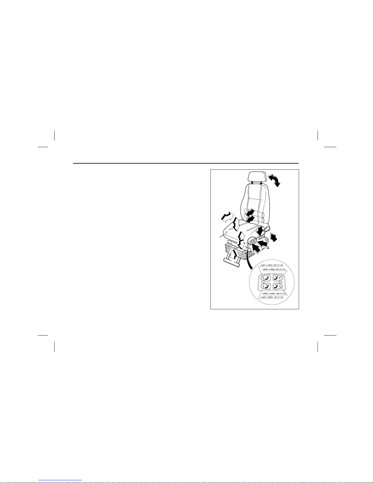
How to use air suspension seat
Air suspension seat can be infinitly adjusted to suit the weight of the driver.
Height Adjustment Tilt Adjustment(RR) Tilt Adjustment(FRT) Back Angle
Lumbar Support(Lower)Lumbar Support(Upper)Slide Adjustment
Page 14
12
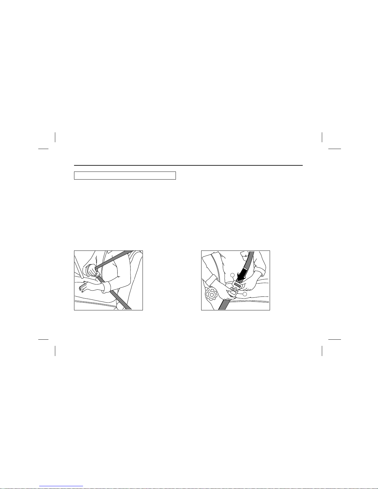
The vehicle is equipped with three point type(driver’s)
and reel type(passenger’s)
Every person who drives or rides in this vehicle
should wear a seat belt at all time.
The buzzer will sound, if the driver’s seat belt is not
fastened when the ignition switch is turned to the
“ON” position.
1) Pull the belt evenly out of the retractor and guide
it across the body making certain that it is not
twisted.
The seatback should not be in a reclining position
anymore than needed for comfort.
2) Insert the metal latch plate ڹ into the buckle ں.
3) To remove the belt, depress the red push button
on the buckle.
And the belt wil roll up automatically.
4) When the driver’s seat belt is not in use, adjust
the latch plate ڹ within 10
cm
from the seat loop.
The belt must not be twisted when fitted.
Do not wear the shoulder belt across the neck or
under your outer arm.
Seat Belts
1
2
Page 15
13
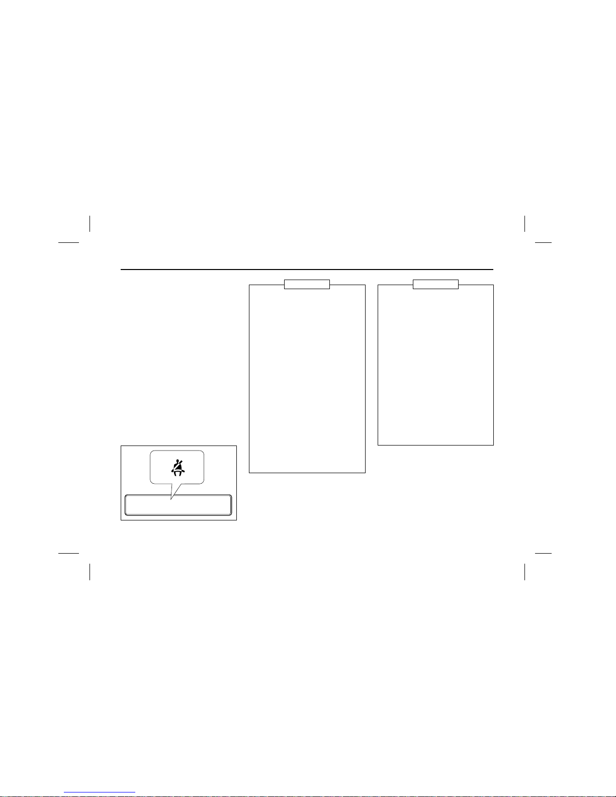
Seat belt warning lamp
The seat belt warning lamp comes on
when the ignition switch is placed in
the “ON” position unless the driver’s
seat belt is securely fastened.
Pilot indicator lamps
1. Never use the belt for more
than one person at a time.
2. Never wear the belts twisted.
3. Make sure seat belts or their
attachments not to be thrusted
in metal parts of the seat or
the door.
4. Seat belts should be adjusted
as firmly as possible.
5. Do not wear seat belts low
under your shoulder.
6. If you replace your seat belts
incorrectly, you may by injured
by hardware of the belts at
sudden stops.
7. Do not wear your seat belts
with hard or breakable objects
such as glasses, pens, etc. put
into the pocket of your upper
garment.
NOTICE
1. Periodically inspect all parts of
the belts and replace any damaged parts.
2. Make sure that the belts are
not to be damaged by sharp
edged objects.
3. The belts should be changed if
webbing has become frayed or
damaged.
4. Check if fixing bolts have been
firmly installed to the floor.
5. Always keep the seat belts
clean and dry.
6. Clean only with tepid soapy
water.
7. Do not bleach or dye seat
belts.
CAUTION
Page 16
14
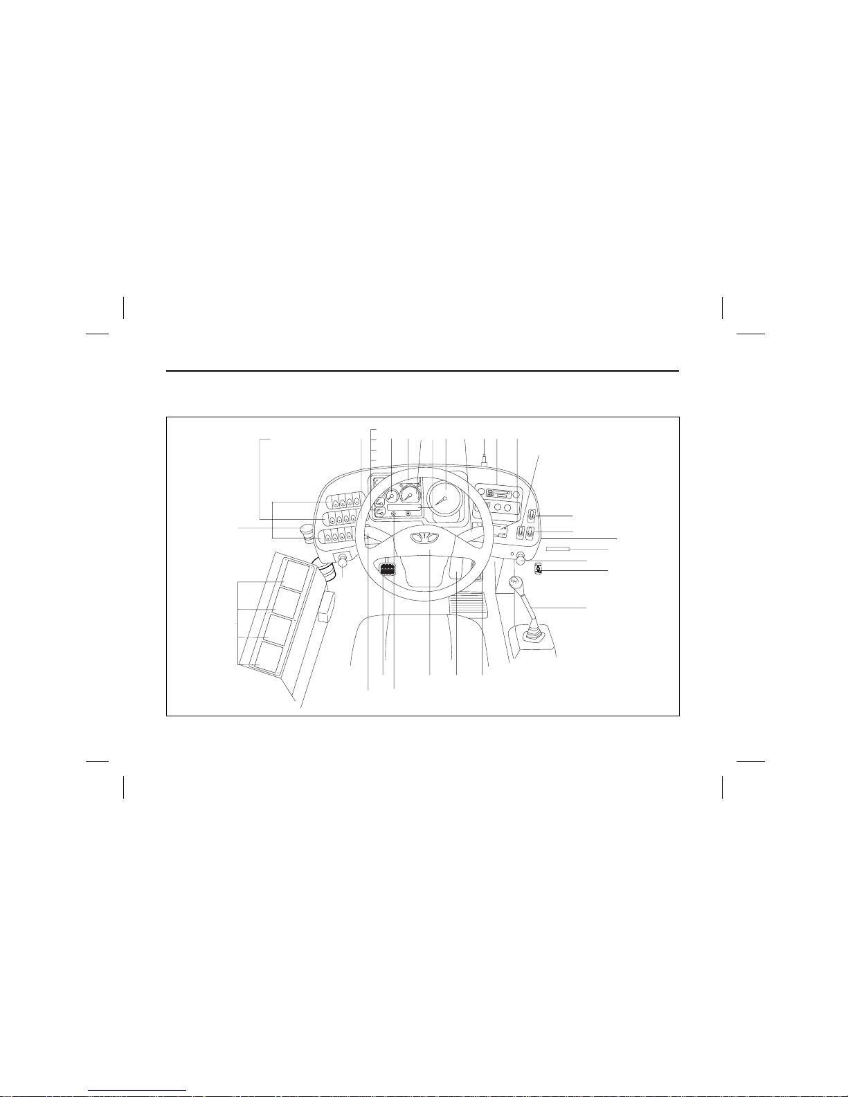
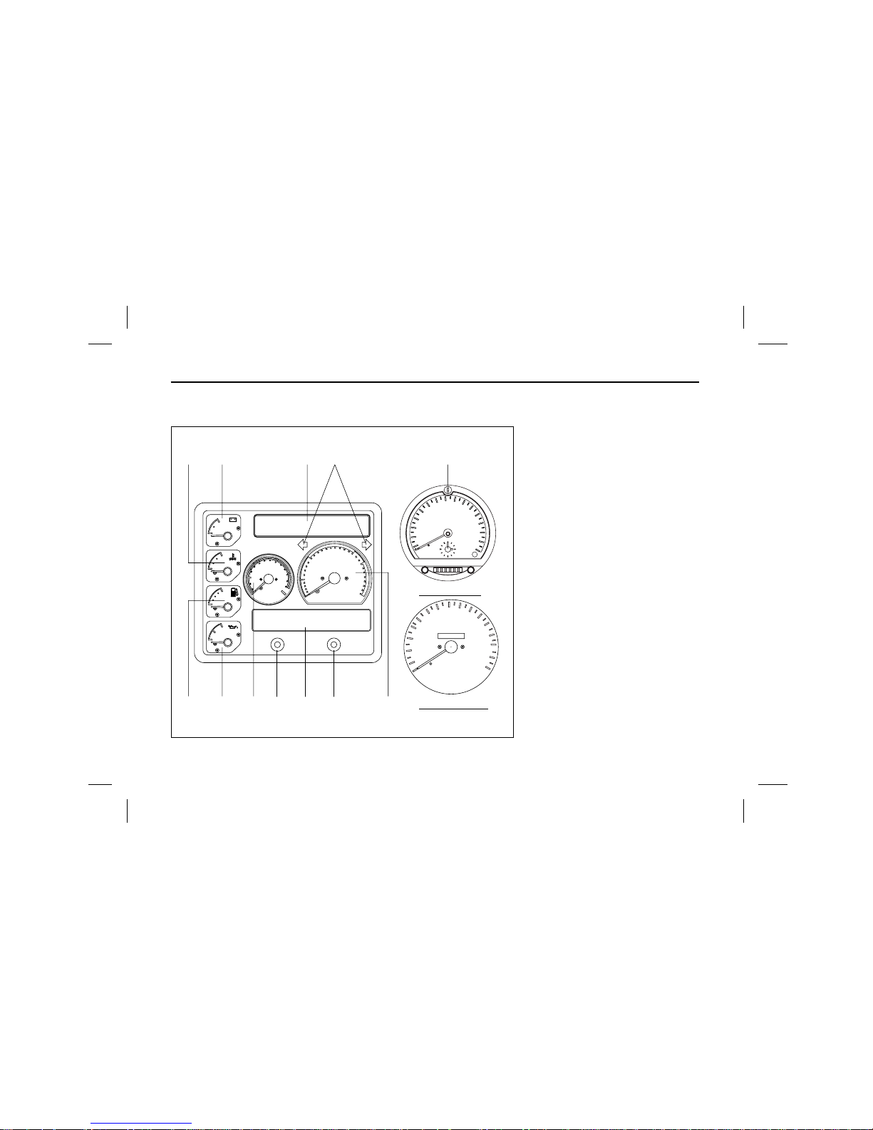
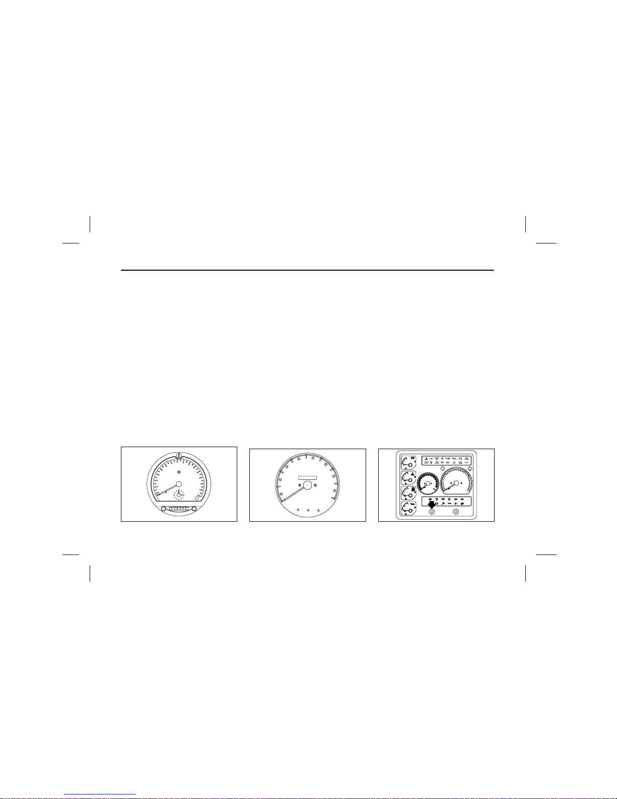
INSTRUMENTS, SWITCHES AND CONTROLS
11
18
202223
24
27
26
30
29
25
56798
21
13 17
10
1
2
3
4
14
19
15
32
12
31
28
Page 17
15
ҧThe quantities or locations of switches could be different from the figure, because the switches could be added or
omitted, or locations could be changed by the requirements of customers.
LEGEND OF INSTRUMENT PANEL AND OTHER DEVICES
No. Description No. Description No. Description
1 Voltage meter
2
Engine coolant temperature gauge
3 Fuel gauge–Engine
4 Engine oil pressure
5 Air pressure gauge
6 Upper pilot lamps
7 Engine RPM gauge
8 Lower pilot lamps
9 Tachograph (OPTION)
Speedometer (OPTION)
10 Door opening switch (FRT)
11 Door opening switch(MID) (OPT)
12 Microphone stand
13 Radio & Cassette player
14 Switches
15 Door opening switch(RR) (OPT)
17 Defroster controller
18 Engine idling knob
19 Shift lever
(Except auto transmission)
20 Accelerator pedal
21 Wiper control and exhaust
brake lever
22 Brake pedal
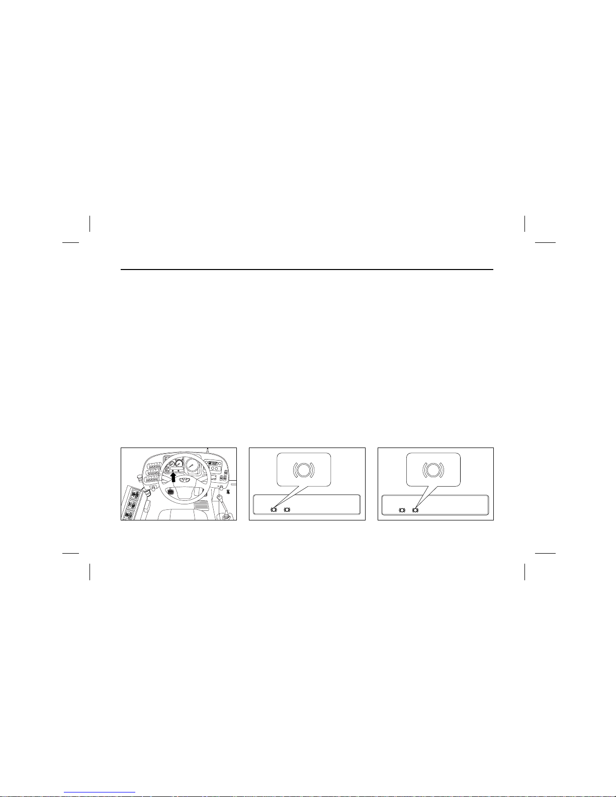
23 Horn switch
24 Bulb check
25 Steering wheel
26 Head & Direction lamp lever
27 Clutch pedal
28 Valve–cab control
29 Clutch oil reservoir
30 Control panel (OPTION)
31 Door controller
32 Cup holder (BM090, BS106)
Page 18
16
ATTACHMENTS OF STEERING COLUMN
Steering wheel and horn button
The steering wheel should not be
turned while the vehicle is stationary
as it adversely affects the tires and
steering system.
Horn button is equipped on the middle of steering wheel.
Steering wheel adjustment
Type A : Tilt & Telescopic
(BH115E,BH120E)
(BM090/BS090/BS106 : OPTION)
Adjust the steering wheel to the
desired position after pulling lock
lever.
Adjusting angle : 8°
Travel : 40mm
Type B : Fixed (BM090, BS106)
Starter switch
Starter switch operates in the 4
stages as follows :
ҮLOCK : The key can be inserted or
removed only when the switch is in
this position.
ҮACC : This position turns on the
radio, digital clock, cigarette lighter
and consent.
unlock
3°
5°
lock
20mm
20mm
Page 19
17
ҮON : This position turns on the
electrical equipment. During the
vehicle operation, hold the key in
this position.
ҧWhen the key is in “ON” position,
the engine is automatically preheated according to outdoor temperature. Pre–heater warning
lamp blinks for 0.3 second at a
higher temperature(coolant temp. :
above 25°
C
) and for 18 seconds
at a lower temperature(coolant
temp
.: below 25°
C
), during
which the engine is preheated for
20 seconds.
ҮSTART : Once the engine is start-
ed, it is preheated automatically
according to outdoor temperature
(until coolant temperature becomes
25°
C
or up to 6 minutes). This
improves the engine condition.
Turn signal switch
Move this combination switch lever in
the desired direction so that the corresponding turn signal lamp operates
and causes the turn signal indicator
lamp on the instrument panel to flash.
The switch lever returns automatically to the neutral position when the
steering wheel is returned to the
reverse direction. When head lamp
switch is in 2nd stage simultaneously
with turn signal lamp “ON”, cornering
lamp also comes on.
LOCK
ACC
ON
START
Pilot indicator lamps
Ү
Once the engine started,
release the key immediately.
Ү
Do not exceed 10 seconds for
the operation of starter.
Ү
Gearshift lever should be in
neutral position when attempting
to start the engine.
CAUTION
Page 20
18
High beam switch
When the head lamps are on, pulling
the lever down lights up not only the
head lamps with high beam but also
the high beam indicator lamp. When
pulling it up, head lamps with low
beam are on.
Passing lamp switch
To light up passing lamps at any
time, pull up the lever towards the
steering wheel.
The lever will return to the OFF position when released.
Lamp switch(turn type)
Lamp switch operates in two stages
as follows :
1st stage : tail lamp, license plate
lamp, instrument panel
lamp, clearance lamp
2nd stage:tail lamp, license plate
lamp, instrument panel
lamp, clearance lamp,
head lamp, cornering
lamp(simultaneously with
turn signal lamp “ON”)
Windshield wiper switch
The windshield wiper switch has 3
positions to control the windshield
wiper.
1. OFF ˞ Off
2. INT ˞ Intermittent wipe
3. LO ˞ Continuous wipe, slow speed
4. HI ˞ Continuous wipe, fast speed
high beam
(passing)
high beam
low beam
2nd stage
1st stage
OFF
1
2
3
4
Do not operate the wipers when the
windshield remains dry. They may
scratch the windshield glass. Do not
operate the wipers if they are covered with snow or ice as this may
damage the wiper system.
NOTICE
Page 21
19
Wiper speed control switch
The desired intermittent operation
time can be controlled by turning the
knob when the wiper switch is in
“INT” position.
Windshield washer switch
To let washer fluid spray on the windshield, press and hold the center button of switch.
And the windshield wipers are simultaneously operated for 2–3 cycles.
Exhaust brake switch
The exhaust brake system is
designed to shut off exhaust pipe
when the engine brake is applied,
resulting in assisting brake action.
When the switch lever is pushed
downward, and clutch and accelerator
pedals are released, the indicator
lamp comes on showing that the
exhaust brake is in operation. When
the clutch and accelerator pedals are
depressed, the exhaust brake stops
working.
Hazard warning flasher switch
When the right–hand lever is pushed
upward, all the turn signal lamps are
made to flash regardless of the turn
signal switch position.
The hazard warning flasher switch is
to be used when your vehicle gets in
a traffic hazard or is parked in the
darkness.
Page 22
20
PERIPHERAL DEVICES OF STEERING COLUMN
Idle control knob
(Except MT643 auto T/M)
Turning the knob clockwise after cold
starting of the engine will increase
idling speed and thus facilitate quick
normalization of the engine coolant
temperature.
Always drive with the knob turned
back home.
Idle control valve
(For MT643 auto T/M)
Valve position
• FAST IDLE (UP) : 900~1000rpm.
• IDLE (DOWN) : 550~650rpm.
Battery switch
It controls the entire electrical circuits with the exception of parking
lamps, hazard warning flashers. The
electrical circuits are energized when
the battery main switch is pressed.
I
D
L
I
N
G
H
.
.
L
ascending
position
IDLE
FAST
IDLE
Do not use this knob to stop the
engine.
NOTICE
Page 23
21
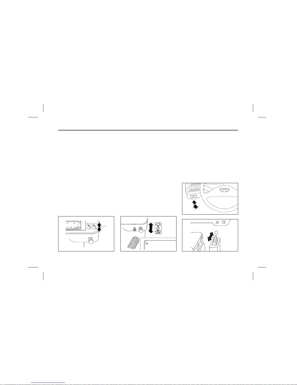
Door opening switch
The entrance door is operated by the
air cylinders as the door opening
switches on.
Manual door opening switch
When the manual door opening
switch is placed at “auto” position, the
doors are operated by the door opening switches, or when the switch is
placed at “manual” position, the doors
are not operated by the door opening
switch and can be opened or closed
by the hands.
Air parking brake switch
When the switch is pushed, the parking brake is actuated and the indicator lamp comes on. pushed one more
the switch, releases the brake. Make
sure that the indicator lamp is off
before driving off.
I
D
L
I
N
G
H
.
.
L
(Toggle switch type)
I
D
L
I
N
G
H
.
.
L
Type A : Cab control valve
Type B : Gradual control
Page 24
22
ABS/ASR check switch(OPTION)
The switch used for self Diagnosis of
ABS/ASR system.
It needs for a car mechanics, but not
used for a driver usually, push the
button about 3 seconds, self diagnosis started and the ABS/ASR warning
lamp blinker on instrument panel.
ABS ARS
ABS
ABS ARS
ASR
POWER
POWE
R
A
I
R
C
O
ND
I
TI
O
N
ER
POWER
A
UT
O
V
E
N
T
IL
A
T
O
R
A
I
RC
OND
I
T
I
O
N
E
R
1
2
3
4
Page 25
23
Engine check / clear switch
(For DE12TiS ENG.)
When engine malfunction pilot lamp
comes on, follow the below procedure
to solve the problem.
1. To check error type pressing
engine check switch.
With pressing this switch, engine
malfunction lamp blinkers according to the error types.
(Example)
Error code 12 : prestroke control error
ҮError code
1. Engine check switch (Blue color)
2. Engine clear switch (Black color)
2. After repairing defects according to
the engine maintenance manual,
press the engine clear switch for
5seconds to remove the errors on
ECU.
Pilot indicator lamps
CHECK
ENGINE
CHECK
ENGINE
CLEAR
1 2
ON
OFF
Malfunction
Pilot lamp
No. Defects
01 Normal
12 Prestroke control error
13 Prestroke sensor error
14 Prestroke offset error
15 Prestroke actuater power error
16 Engine rpm sensor error
21 Coolant temp. sensor error
22 Fuel rack sensor error
23 Air heater relay error
Page 26
24
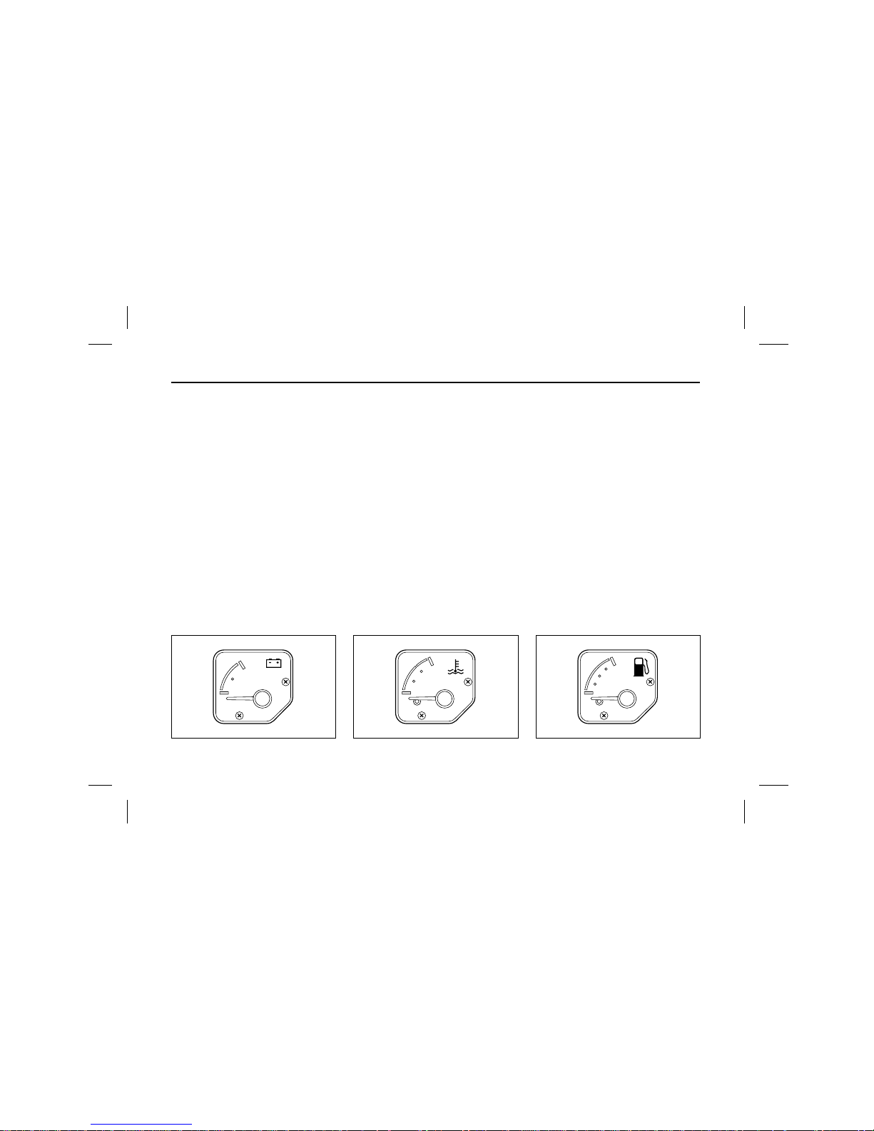
INSTRUMENTS AND INDICATOR LAMPS
1. Voltmeter
2. Engine coolant temperature gauge
3. Fuel gauge
4. Engine oil pressure gauge
5. Air pressure gauge
6. Engine tachometer
(If the engine RPM indicating function is included in tachograph, this
gauge is substituted to blank cover.)
7. Tachograph
(BH115E, BH120E)
(BM090/BS106 : OPT)
Speedometer (BM090, BS106)
8. Bulb check switch
9. Cover
10. Turn signal/hazard warning indicator
11. Upper pilot indicator lamps
12. Lower pilot indicator lamps
32
24
16
0
0
4
8
C
H
E
F
0
1
2
3
x1000rpm
0
3
6
9
12
15
kg/cm
A I R
2
7101112
3458129 6
7
0
20
40
60
80
100
120
140
160
Km/h
0000000
Tachograph
Speedometer
0
80
000000
km/h
60
40
20
160
140
120
100
Page 27
25
Voltmeter
The voltmeter indicates the battery
condition. Check the voltmeter reading with the engine running. The
gauge needle should stand between
the reading of 24 and 28.
Temperature gauge
The gauge indicates the engine
coolant temperature. If the gauge
needle stands below the red colored
zone, it means that engine coolant
temperature is normal.
If the needle stands in “H”(overheating), stop the vehicle and run the
engine at a moderately fast idle
speed or put the gear in lower position to reduce engine load. If the
vehicle is operated in abnormal condition, engine performance will be
reduced and fuel consumption will be
increased.
Fuel gauge
This gauge indicates fuel level of the
fuel tank all the time regardless of the
starter switch position.
The capital letter “E” represents
almost “empty”. Top–up the fuel tank
before the gauge indicates “E”.
32
24
16
0
C
H
E
F
Page 28
26
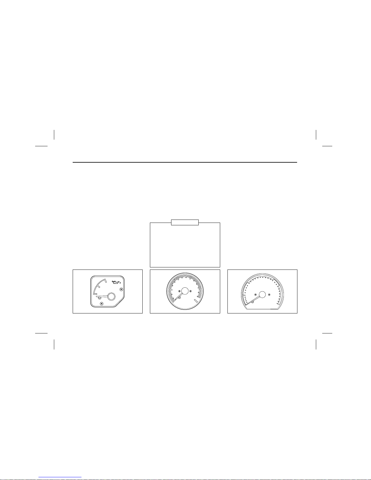
Oil pressure gauge
This gauge indicates oil pressure in
the engine lubricating system. The
indication of the gauge should be 1–3
kg/cm2when the engine is at idle ; it
should be 3–6.5
kg/cm2when the
engine is running at medium speed.
When the gauge needle does not
move upward at all or hydraulic pressure changes abruptly, check the oil
level in the engine crankcase. If the
oil level is found normal, have the
hydraulic system checked by your
nearest Daewoo dealer.
Do not run the engine with low oil
pressure indication.
Air pressure gauge
Air pressure gauge indicates air pressure in the air tanks. While driving,
the gauge needle must be within the
range of 5.3–8.2
kg/cm2.
Be habitual of watching the gauge,
while driving, to make sure the gauge
needle indicates the normal conditions.
Engine tachometer
The tachometer indicates the engine
speed in revolutions per minute(rpm)
and red colored zone represents
critical engine speed.
Excessively high engine rpm(red colored zone) may cause damage to the
engine.
To drive economically, keep the
engine within 1,000Ŕ2,000rpm.
Maximum allowable engine speed :
D1146 ENG : 2,500rpm.
D1146Ti/DE12/DE12T ENG.
: 2,200rpm.
DE08TiS ENG : 2,300rpm.
DE12Ti/DE12TiS ENG.:2,100rpm
1
4
8
0
3
6
9
12
15
kg/cm
A I R
A
O
H
A
I
R
F
U
L
L
A
I
R
2
0
1
2
3
x1000rpm
If the gauge needle stands in the
red zone, warning lamp comes on
and alarm buzzer sounds. Immediately stop the vehicle, check for
unusual conditions, run the engine
at a moderately fast idle speed to
increase air pressure, then drive off.
NOTICE
Page 29
27
Tachograph
(BH115E, BH120E)
(BM090/BS090/BS106 : OPT)
The tachograph is consisted of odometer and clock. The vehicle speed
and running distances are registered
in a single chart. The speedmeter
indicates the vehicle speed in kilometer per hour(
km/h
). The odometer indicates individual trip distances. The
odometer records the total distance in
km
. The unit of registered distance is
loom.
For further information refer to
“TACHOGRAPH” on page.
Speedometer (BM090, BS106)
The speedometer is consisted of
odometer and clock. The vehicle
speed and running distances are registered in a single chart. The speedmeter indicates the vehicle speed in
kilometer per hour(
km/h
). The odometer indicates individual trip distances.
The odometer records the total distance in
km
. The unit of registered
distance is loom.
For further information refer to
“SPEEDOMETER” on page.
Bulb check switch
When bulb check switch is pressed,
warning lamp on instrument panel
comes on.
And also the warning buzzer sounds.
Before driving, use this switch to
check that all warning lamps including speed indicator lamps and their
circuits are operating normally.
7
0
20
40
60
80
100
120
140
160
Km/h
0000000
0
80
000000
km/h
0-80 101-160
81-100
60
40
20
160
140
120
100
32
24
16
0
0
4
8
C
H
E
F
0
1
2
3
x1000rpm
0
3
6
9
12
15
kg/cm
A I R
2
SPEED
T/M
SAFETY
ABS ASR
E
Page 30

28
Turn signal indicator lamp
When the turn signal switch or hazard warning flasher switch is turned
on, the turn signal indicator lamp
flashes to indicate the operation of
the external turn signal lamps or hazard warning flashers.
Page 31

29
UPPER PILOT INDICATOR LAMPS
Type A
9 10 11 12 13 14 15 16
12 4
5 6783
1. Engine coolant temperature (high)
2. Air tank pressure (low)
3. Brake oil level (low) (OPT : AOH Brake)
4. Seat belt (Unfastened)
5. Parking lamp (on)
6. Engine oil pressure (low)
7. Battery charging
8. Engine door (open)
9. Emergency door (open) (OPTION)
10. Mirror defroster (on) (OPTION)
11. Air dryer operation (on) (OPTION)
12. Engine preheat (on)
13. High beam (on)
14. Transmission neutral position
15. Entrance door (open)
16. Passenger’s stop order (OPTION)
Page 32

30
Type B
9 10 11 12 13 14 15 16
12 4 5
6783
321
1. Engine coolant temperature (high)
2. Air tank pressure (low, Front)
3. Air tank pressure (low, MID.)
4. Air tank pressure (low, Rear EMER.)
5. Brake oil level (low) (OPT : AOH Brake)
6. Engine oil pressure (low)
7. Battery charging
8. Engine preheat (on)
9. Seat belt (Unfastened)
10. Engine door (open)
11. Air dryer operation (on) (OPTION)
12. Engine room fire warning (OPTION)
13. High beam (on)
14. Transmission neutral position
15. Entrance door (open)
16. Passenger’s stop order (OPTION)
Page 33

31
Type C
9 10 11 12 13 14 15 16
1234
5 6 78
321
1. Engine coolant temperature (high)
2. Air tank pressure (low, Front)
3. Air tank pressure (low, MID.)
4. Air tank pressure (low, Rear EMER)
5. Brake oil level (low) (OPT : AOH Brake)
6. Engine oil pressure (low)
7. Battery charging
8. Engine room fire warning (OPT)
9. Seat belt (Unfastened)
10. Engine door (open)
11. Air dryer operation (on) (OPTION)
12. Engine preheat (on)
13. High beam (on)
14. Transmission neutral position
15. Entrance door (open)
16. Passenger’s stop order (OPTION)
Page 34

32
Type D
9 10 11 12 13 14 15 16
12 4
5 678
1. Engine coolant temperature (high)
2. Air tank pressure (low)
3. Brake oil level (low) (OPT : AOH Brake)
4. Seat belt (Unfastened)
5. Parking lamp (on)
6. Engine oil pressure (low)
7. Battery charging
8. Engine door (open)
9. Emergency door warning (open) (OPTION)
10. Mirror defroster (on) (OPTION)
11. Air dryer operation (on) (OPTION)
12. Engine preheat (on)
13. High beam (on)
14. Transmission neutral position
15. Entrance door (open)
16. Passenger’s stop order (OPTION)
Page 35

33
Type E
9 10 11 12 13 14 15 16
12 4
6783 5
3
2
1
1. Engine coolant temperature (high)
2. Air tank pressure (low, Front)
3. Air tank pressure (low, MID.)
4. Air tank pressure (low, Rear EMER)
5. Brake oil level (low) (OPT : AOH Brake)
6. Engine oil pressure (low)
7. Battery charging
8. Engine room fire warning (OPT)
9. Seat belt (Unfastened)
10. Engine door (open)
11. Air dryer operation (on) (OPTION)
12. Engine preheat (on)
13. High beam (on)
14. Transmission neutral position
15. Retarder warning (OPTION)
16. Passenger’s stop order (OPTION)
Page 36

34
Engine coolant temperature (high)
When the temperatue of engine coolant
becomes near 100°C (210°F) the warning
lamp turns on.
Air tank pressure (low)
(Type A) (Type B, C, E) (Type D)
The indicator lamp comes on and the warning buzzer is
operated simultaneously, when air pressure within the air
tank is lowered to 5.3kg/cm
2
.
If the air pressure indicator lamp comes on while driving,
stop the vehicle and check to locate the cause of trouble
and avioc driving with the indicator lamp turned on.
Repeated application of service brakes could cause temporary lowering of air pressure. In such an instance, keep
the engine running as fast idle until the indicator lamp
goes out.
Seat belt (Unfastened)
The seat belt warning lamp comes on when
the ignition switch is placed in the “ON”
position unless the driver's seat belt is
securely fastened.
Parking lamp (on)
(Type A)
The parking brake indicator lamp comes
on when the parking brake lever is pulled
with the starter switch “ON”. The parking
brake indicator lamp does not indicate the
action of the parking brake. Make sure to
pull the parking brake lever fully when parking the vehicle.
Before moving the vehicle, be sure to check that the parking brake indicator lamp is off.
PARKING
AIR
321
(Type D)
Page 37

Engine oil pressure (low)
The lamp comes on when the battery main
switch is operated and goes out as the
engine is started and pressure of oil in the
engine is increased.
If the lamp comes on while driving, stop the engine immediately and check the level of oil in the engine crank-case.
If the oil level is normal, restrictions in the oil filter or a
trouble in the lubricating system may be indicated and the
system should be checked at your nearest service station.
Do not run the engine with the lamp illuminated.
Battery charging
The indicator lamp comes on when the battery main switch is operated and goes out
as the engine is started and alternator circuit is brought into normal function.
The indicator lamp comes on while the engine is running,
it indicates that the alternator circuit is malfunctioning, then
immediately stop the vehicle and have the alternator ciruit
checked by your nearest service shop.
Engine door (open)
(Type A, B, C, E) (Type D)
The indicator lamp comes on when the engine room door
is opened. If the lamp turns on even after closing the door,
check the door lock and lock the door firmly
Emergency door (open)
(Type A) (Type D)
The indicator lamp comes on when the emergency door
is opened. If the lamp comes on even after closing the
door, check the door lock and lock the door firmly..
35
ENG.
DOOR
EMER.
DOOR
Page 38

Mirror defroster (on) (OPTION)
Pressing the side mirror defroster switch, the
indicator lamp “ON” and the defrosting coil
in the mirror starts actuating.
Air dryer operation (on) (OPTION)
(Type A,B,C,E) (Type D)
The indicator lamp comes on when the air dryer is operating. (Air dryer heating system on)
Engine preheat (on)
This lamp is designed to indicate preheating
of the engine. It comes on when starter
switch is positioned “ON”, while it goes out
when the preheating is completed.
High beam (on)
The high beam indicator lamp comes on
when head lamps with high beam are in
use.
Transmission neutral position
The indicator lamp comes on when the gear
shift lever locates in neutral position.
Entrance door (open)
(Type A,B,C,E) (Type D)
The lamp comes on while the entrance door is opened.
Passenger's stop order (OPTION)
(Type A,B,C,E) (Type D)
When the passenger push the button between windows,
the buzzer sounds and this lamp comes on.
36
AIR
DRYER
STOP
ENT.
DOOR
Page 39

Engine room fire warning (OPTION)
The indicator lamp comes on when the
engien room is fired.
Retarder system warning (OPTION)
At the case that additional retarding system
is applied, while the retarder is operating,
the indicator lamp comes on.
37
ENG.
ROOM
Page 40

38
LOWER PILOT INDICATOR LAMPS
Type A
9 10 11 12 13 14 15
1234
5 6 7 8
E
ABS
ASR
CHECK
1. Safety equipment operation
2. Retarder system operation (OPTION)
3. Retarder system warning (OPTION)
4. Exhaust brake operation
5. Speed 3 indication (OPTION)
6. Electronically controlled air
Suspension operation (OPTION)
7. Air condition warning (OPTION)
8. MIL
9. Brake pad wear warning
10. ABS system warning (OPTION)
11. ASR system warning (OPTION)
12. Auto greaser operation (OPTION)
13. Speed limiter operation (OPTION)
14. Speed 1 indication (OPTION)
15. Speed 2 indication (OPTION)
Page 41

39
Type B
10 11 12 13 14 15
1234
5 6 7 8
RTD RTD
E
ABS
ASR
1. Safety equipment operation
2. Retarder system operation (OPTION)
3. Retarder system warning (OPTION)
4. Exhaust brake operation
5. Speed 3 indication (OPTION)
6. Electronically controlled air
Suspension operation (OPTION)
7. Transmission temperature
8. Do not shift
10. ABS system warning (OPTION)
11. ASR system warning (OPTION)
12. Auto greaser operation (OPTION)
13. Speed limiter operation (OPTION)
14. Speed 1 indication (OPTION)
15. Speed 2 indication (OPTION)
Page 42

40
Type C
9 10 11 12 13 14 15
12345678
ABS
ASR
E
1. Safety equipment operation
2. Defroster operation
3. Fuel empty warning
4. Exhaust brake operation
5. Battery main S/W operation
6. Retarder operation (OPTION)
7. T/M temperature warning
8. Air condition warning (OPTION)
9. Over speed warning (OPTION)
10. ABS system warning (OPTION)
11. ASR system warning (OPTION)
12. Auto greaser operation (OPTION)
13. Light 1 step operation
14. Head lamp low beam (on)
15. Front fog lamp operation
Page 43

41
Type D
10 11 12 13 14 15
12 34
5 678
E
ABS
ASR
FRONT
DOOR
MID.
DOOR
REAR
DOOR
EMER.
V/ V-F
ENG.
ROOM
EMER.
V/ V-M
EMER.
V/ V-R
1. Safety equipment operation
2. Exhaust brake operation
3. Front door opened
4. Middle door opened (OPTION)
5. Rear door opened (OPTION)
6. Front emergency valve operation (OPT)
7. Middle emergency valve operation (OPT)
8. Rear emergency valve operation (OPT)
10. ABS system warning (OPTION)
11. ASR system warning (OPTION)
12. Auto greaser operation (OPTION)
13. Engine room fire warning (OPTION)
14. Front fog lamp operation
15. Rear fog lamp operation (OPTION)
Page 44

42
Type E
109 11 12 13 14 15
12 34
5 678
E
P
ABS
ASR
FRONT
DOOR
MID.
DOOR
REAR
DOOR
EMER.
V/ V-F
EMER.
V/ V-M
EMER.
V/ V-R
CHECK
1. Safety equipment operation
2. Exhaust brake operation
3. Front door opened
4. Middle door opened (OPTION)
5. Rear door opened (OPTION)
6. Front emergency valve operation (OPT)
7. Middle emergency valve operation (OPT)
8. Rear emergency valve operation (OPT)
9. MIL
10. ABS system warning (OPTION)
11. ASR system warning (OPTION)
12. Auto greaser operation (OPTION)
13. Parking lamp (ON)
14. Front fog lamp operation
15. Rear fog lamp operation (OPTION)
Page 45

43
Type F
10 11 12 13 14 15
12 34
5 678
E
P
ABS
ASR
FRONT
DOOR
MID.
DOOR
REAR
DOOR
EMER.
V/ V-F
EMER.
V/ V-M
EMER.
V/ V-R
1. Safety equipment operation
2. Exhaust brake operation
3. Front door opened
4. Middle door opened (OPTION)
5. Rear door opened (OPTION)
6. Front emergency valve operation (OPT)
7. Middle emergency valve operation (OPT)
8. Rear emergency valve operation (OPT)
10. ABS system warning (OPTION)
11. ASR system warning (OPTION)
12. Auto greaser operation (OPTION)
13. Parking lamp (ON)
14. Front fog lamp operation
15. Rear fog lamp operation (OPTION)
Page 46

44
Type G
109 11 12 13 14 15
12 34
5 678
E
P
ABS
ASR
1. Safety equipment operation
2. Exhaust brake operation
3. Speed 1 indication (OPTION)
4. Speed 3 indication (OPTION)
5. Speed 2 indication (OPTION)
6. Parking lamp (ON)
7. Mirror heater (OPTION)
8. Air condition warning (OPTION)
9. Emergency door (OPEN) (OPTION)
10. ABS system warning (OPTION)
11. ASR system warning (OPTION)
12. Auto greaser operation (OPTION)
13. Speed limiter operation (OPTION)
14. Front fog lamp operation
15. Rear fog lamp operation (OPTION)
Page 47

45
Type H
7 8 9 10 11 12
12 34
56
E
ABS
ASR
1. Safety equipment operation
2. Retarder system operation (OPTION)
3. Retarder system warning (OPTION)
4. Exhaust brake operation
5. Speed 3 indication (OPTION)
6. T/M temperature warning
7. ABS system warning (OPTION)
8. ASR system warning (OPTION)
9. Auto greaser operation (OPTION)
10. MIL
11. Speed 1 indication (OPTION)
12. Speed 2 indication (OPTION)
Page 48

46
Type I
1091112131415
1234
5 678
E
FRONT
DOOR
MID.
DOOR
REAR
DOOR
EMER.
V/ V-F
EMER.
V/ V-M
EMER.
V/ V-R
ABS
ASR
P
1. Safety equipment operation
2. Exhaust brake operation
3. Front door opened
4. Middle door opened (OPTION)
5. Rear door opened (OPTION)
6. Front emergency valve operation (OPT)
7. Middle emergency valve operation (OPT)
8. Rear emergency valve operation (OPT)
9. Auto greaser operation (OPTION)
10. ABS system warning (OPTION)
11. ASR system warning (OPTION)
12. Retarder system operation (OPTION)
13. Parking lamp (ON)
14. Front fog lamp operation
15. Rear fog lamp operation (OPTION)
Page 49

47
Type J
9 10 11 12 13 14 15
12345678
E
ABS
ASR
1. Safety equipment operation
2. Defroster operation
3. Fuel empty warning
4. Exhaust brake operation
5. Battery main S/W operation
6. Retarder operation (OPTION)
7. T/M temperature warning
8. Do not shift
9. Over speed warning (OPTION)
10. ABS system warning (OPTION)
11. ASR system warning (OPTION)
12. Auto greaser operation (OPTION)
13. Light 1 step operation
14. Head lamp low beam (on)
15. Front fog lamp (on)
Page 50

Safety equipment operation
(Type A-G, I, J) (Type H)
When the passenger stands at entrance step, the rear
door is not closed, this lamp comes on.
Retarder system operation (OPTION)
(Type A, C, H-J) (Type B)
For automatic transmission, while the retarder is operating,
the indicator lamp comes on.
Retarder system warning (OPTION)
(Type A, H) (Type B)
At the case that additional retarding system is applied,
while the retarder is operating, the indicator lamp comes
on.
Exhaust brake operation
The indicator lamp comes on while the
exhaust brake is operating.
Electronically controlled air suspension operation (OPTION)
The height of the body is controlled automatically in accordance with the weight and
speed of the vehicle, the lamps comes on
when the system is operating.
48
SAFETY
E
ECS
RTD
RTD
Page 51

49
Speed 1 indication (OPTION)
(Type A, B, G) (Type H)
At the vehicle speed in 0~5km/H the lamp comes on, also
the left Yellow-Green marker lamp on the roof at the front
of the vehicle, lights on.
Speed 3 indication (OPTION)
(Type A, B, G) (Type H)
At the vehicle speed in 0~5km/H the lamp comes on, also
the left Yellow-Green marker lamp on the roof at the front
of the vehicle, lights on.
Speed 2 indication (OPTION)
(Type A, B, G) (Type H)
At the vehicle speed in 80km/H the lamp comes on, also
the middle red marker lamp on the roof at the front of the
vehicle, lights on.
Brake pad wear warning
The indicator lamp comes on when the
brake limning is too much worn out.
Over speed warning (OPTION)
At the vehicle speed in 80km/H the lamp
comes on, also the middle red marker lamp
on the roof at the front of the vehicle, lights
on.
SPEED 1
SPEED 2
SPEED 3
SPEED
Page 52

ABS system warning (OPTION)
As the battery relay and the starter switches are turned on, the indicator lamp comes
on and goes put when the vehicle speed
reach to 5~10km/H. If the lamp keeps lighting while driving, the ABS/ARS system is out
of order and should be checked.
ASR system warning (OPTION)
As the battery relay and the starter switches are turned on, the indicator lamp comes
on and goes out in a short time. If the lamp
keeps lighting while driving, the ASR system
is out of order and should be checked.
Auto greaser operation (OPTION)
The indicator lamp comes on while the auto
greasing system is operating or the main
pressure of the system drops below
25kg/mm
2
.
Speed limiter operation (OPTION)
The lamp comes on while the speed limiter
system is operating.
Air conditioner warning (OPTION)
The lamp comes on when the high/low voltage is flowing or the compressor clutch is
disconnected, etc.
Head lamp low beam (ON)
The high beam indicator lamp comes on
when head lamps with high beam are in
use.
Engine malfunction lamp
Check the state of engine operating when
starter key on.
This lamp flashes at engine cranking in
normal of engine operating.
Otherwise, on abnormal of Engine operating, lamp come
on continuously and come on during of engine running.
50
ASR
CHECK
SPEED
LIMITER
ABS
When the ABS/ASR system is out of order, the brake
system works as if ABS system is not applied.
NOTICE
Page 53

51
Transmission temperature
(Type B) (Type C, J) (Type H)
The lamp comes on when the oil temperature of automatic
transmission is overheated beyond the specified value.
Shift
(Type B) (Type J)
The lamp comes on when the engine RPM rises beyond
shifting point.
Defroster operation
For automatic transmission, while the
retarder is operating, the indicator lamp
comes on.
When the defroster in operating for refuse frost, the indicator lamp comes on.
Fuel empty warning
When fuel indiator needle located around
Empty state, (Red line) indicator lamp come
on.
Battery main S/W operating
The indicator lamp comes on when the bat-
tery relay switch is operated and goes out
as the engine is started and alternator cir-
cuit is btought into normal function.
The indicator lamp comes on while the engine is running,
it indicates that the alternator circuit is malfuncitioning, then
immediately stop the vehicle and have the alternator circuit checked by your nearest service shop.
Light 1 step operating
At the vehicle speed in 0~5km/H the lamp
comes on, also the Yellow-Green marker
lamp on the roof at the front of the vehicle,
lights on.
At the tail lamps come on, indicator lamp come on.
T/M
TEMP.
SHIFT T/M
Page 54

52
Front fog lamp operation
The lamp comes on when the front fog lamp
switch is turned “ON”.
Rear fog lamp operation (OPTION)
The lamp comes on when the tail lamp is
“ON” and it light off while tail lamp come
off.
Against rear fog lamp keep up “OFF” while tail lamp is
comes on.
Parking lamp (On)
The parking brake indicator lamp comes on
when the parking brake lever is pulled with
the starter switch “ON”.
The parking brake indicator lamp does not indicate the
action of the parking brake. Make sure to pull the parking brake lever fully when parking the vehicle.
Before moving the vehicle, be sure to check that the parking brake indicator lamp is off.
Front door operation
When the front door is opened, this indica-
tor lamp comes on.
Middle door operation (OPTION)
The indicator lamp comes on when the mid-
dle door is opened.
Rear door operation (OPTION)
The indicator lamp comes on when rear
door is opened.
Front emergency valve operation (OPTION)
The indicator lamp comes on while the mid-
dle emergency valve operation.
FRONT
DOOR
MID.
DOOR
REAR
DOOR
EMER
V/V-F
P
Page 55

53
Middle emergency valve operation (OPTION)
The indicator lamp comes on while the
Mid. emergency vlave operation.
Rear emergency valve operation (OPTION)
The indicator lamp comes on while the
rear emergency valve operation.
Engine room fire warning (OPTION)
The indicator lamp comes on when the
engien room is fired.
Mirror defroster (ON) (OPTION)
Pressing the side mirror defroster switch, the
indicator lamp “ON” and the defrosting coil
in the mirror starts actuating.
Emergency door (open) (OPTION)
The indicator lamp comes on when the
emergency door is opened. If the lamp
coems on even after closing the door, check
the door lock and lock the door firmly.
EMER
V/V-M
EMER.
DOOR
EMER
V/V-R
ENG.
ROOM
Page 56

54
SWITCHES
Ɓ The quantities or locations of switches could be different from the figure, because the switches could be added or
omitted, and locations could be changed by the requirement of customers.
Page 57

55
Room lamp switch (Floor 1)
Push the switch to light on the first
room lamp (incandescent) from the
entrance door (Front).
Room lamp switch (Floor 2)
(Apply for vehicles with lamp
rack)
Push the switch, light come on the all
room lamp (incandescent) but except
first room lamp at the entrance door
(Front).
Mood lamp switch 1 (OPTION)
(Apply for vehicles with lamp
rack)
Pressing the switch to light on the
mood lamp come on in order odd.
F
F F
Page 58

56
Mood lamp switch 2 (OPTION)
(Apply for vehicles with lamp
rack)
Pressing the switch to light on the
mood lamp in order even.
Room lamp switch (Bulb)
Push the switch to light on the fluorescent room lamps at the passenger’s compartment.
Driver lamp switch
Pressing the switch, the driver’s compartment lamp comes on.
F
B
Page 59

57
Luggage lamp switch (OPTION)
Pressing the switch, the luggage compartment lamps come on. The switch
operates when the light switch is on.
Reading lamp switch (OPTION)
Pressing the switch, reading lamps
below the air–conditioner grill come
on.
Fog lamp switch (Front)
Pressing the switch, the fog lamps
come on to improve your Foreward/
backward vision in fog or snow.
Page 60

58
Fog lamp switch(Rear) (OPTION)
Pressing the switch, the fog lamps
come on to improve your Backward
vision in fog or snow.
Battery main switch
Pressing the switch to light on the
battery lamp come on.
Parking lamp switch (OPTION)
Pressing the switch to light on the
parking lamp lamp come on.
P
Page 61

59
Front ent. door switch (OPTION)
Pressing the switch, front ent. door
lamps upper the front door come on.
Mid. ent. door switch (OPTION)
Pushing the switch, Mid. ent. door
lamps come on.
When Mid door opened.
Rear ent. door switch (OPTION)
Pressubg the switch, rear ent. doorr
lamps comes on when rear ent. door
opened.
Page 62

60
TV/VCR power switch (OPTION)
Pressing the switch, electric power to
TV/VCR is supplied.
Electric fan switch (OPTION)
Pressing the switch, electric fan
power supplied for driver's and passengeeer's fan.
Step lamp switch (OPTION)
Push the switch to light on the search
lamp from the front/middle/rear door.
Page 63

61
Destination board switch (OPT)
Push the switch to light on the destination boards front and rear.
Door rack lamp switch (OPTION)
Pressing the switch, door rack lamps
come on.3
Heater mirror switch (OPTION)
Pressing the switch, provide heater in
mirror.
Page 64

62
ҮPower on by pressing the switch(ڹ),
the indicator lamp(ں) light comes on
Automatically(power off by pressing
the switch(ڹ) again).
ҮTurn to right the contrast switch(ڻ),
the scene state is kept distinctly,
the turning to the bright control
switch(ڼ ) left/right, the bright of
scene is controlled darkly and
brightly.
ҮSelet(ڽ) the camera C1/C2 in case
of two camera installed. C1 is inner
watching camera by pressing the
upper button and other is outer
watching.
ҮSelect the Auto/Manual switch(ھ).
–Auto : Rear situation is displayed
the monitor with operation
on camera in state of shifted reward gear of vehicle.
–Manual : Camera operated by
power on.
ҮPress the light of scene controller
button(ڿ) the scene is drak in night,
othewise in daytime, it’s brighted.
òCAMERAó
1. LENS :It’s possible inputing the a
picture and veiwing 130°
degrees of an angle.
2. COVER : Profected the camera on
water proof stuff.
3. DIN PLUG : Connect the monitor
and camera.
THE CAR VISION SYSTEM FOR VEHICLE (OPTION)
1
234
5
6 7
2
1
3
Page 65

63
HEATING AND DEFROSTING
Heating and defrosting of
driver’s compartment
Move the upper control lever from the
left end of right side, the blower fan
starts to operate and the incoming air
flow increases gradually.
When the middle control lever to the
right side end, in the blower is cycled
in inner.
Otherwise, the lever to the left side end,
the blower is inhaled from outer for circulation.
Heating and defrosting of
driver’s compartment
When the lower control lever is
placed at the left and, the air comes
by two directions, one is to the driver’s foot side and another is to the
windshield glass side.
By moving the control lever to the right
side, the air coming into the foot side
decreases and to the wind shield glass
side increases gradually.
When the lever reaches to the right
end, the air comes in by the windshield
glass side only.
OFF 3OFF 12
OFF 1 2
3
Page 66

64
Heating of passenger's compartment (OPTION)
Power switch
Power on by turning the end of left
side (Light Red color part) to side of
center (Red color) or Right (Dark
color).
HEATER
Controller operator switch
Before press the units controller button, must be operated power switch
(ڹ ), and push the button for unit
selector (ں).
Select the unit No. by pressing the
buttons are ordinary order from unit
No.1 to No.5.
After, the selection fan by turning the
Rotary selector (ڹ) to right side (Dark
Red).
It’s increase highly.
21
HEATER
1
2
321
HEATER
1
2
321 4
HEATER
1
2
(Heater–2EA) (Heater–3EA) (Heater–4EA)
Page 67

65
AIR–CONDITIONING
COOLER (ROOF–ON TYPE) (OPTION)
Temperature controller
(Type A : Rotary type control
panel)
Turning the end of left side(Dark
blue), the temperature of indoor is
decrease lowerly otherwise, turning
the right side(Light blue) it’s increase
highly.
Power switch
The cooler power switch is operated
by pressing the button (2), then cooler blower fan is operated as each
step of fan speed switch (4, 5, 6).
While the cooling operator switch is
not pressed, room air only cirrculates.
Cooling operator switch (3)
Before press the button, must be
operated power switch(1).
Press the switch (3) and cooler starts
operation.
Blower fan operator switch
(4, 5, 6)
Swithc (4) : 60% of max. capacity.
Swithc (5) : 80% of max. capacity.
Swithc (6) : 100% of max. capacity.
Warning indicator (7)
When the refrigerant is flowing the
high/low pressure or the disconnected
of compressor clutch, etc., then the
indicator lamp come on.
POWER
AIRCONDITIONER
1
23456
POWER
AIRCONDITIONER
1
23457
Type ы Type ь
Page 68

66
(Type B : Seesaw type control
panel)
Cooling
ҮFirst start engine and set the room
temperature with the control knob.
ҮPush the cooling/vent switch to
“cooling” side.
ҮPush “ON” the power switch, the all
systems like the compressor, condenser fan and evaporator blower
start operation for cooling.
(The “cooling” indicating lamp
comes on).
ҮWhen the room temperature drops
below the set temperature, the system does air blowing operattion
only, and the room temperature
rises beyond the set temperature,
the system returns to cooling operation automatically.
Ventilation
ҮPush the cooling/vent switch to
“VENT” side.
ҮPush “ON” the power switch, to
maintain adequate room temperature by blowing in the fresh and
cool outdoor air.
ҮAt this time the compressor and
condenser fan do not operate, but
the blowers in the evaporator operate.
Stop
ҮNormal stopping
First push “cooling/vent” switch to
“vent” side, then cooling stops and
the system operates only for ventilation, Push power switch “OFF”,
then all systems stop operation.
ҮEmergency self stopping.
- When refrigerant pressure rises
abnormally high (over 22kg/cm
2
),
the electric clutch of compressor is
disengaged, so the compressor
stops working.
(The “Trouble” indicating lamp
comes on).
In the case that any troubles are
checked in operation, the emergency self stop occurs, this means
the stop of compressor, the condenser and evaporator fan do not
stop and continue operating.
AIR-CONDITIONER
VENT COOLING
COOLINGON
OFF VENT
HIGH
LOW
TEMP
TROUBLE
15 30
Page 69

67
- When refrigerant pressure goes
down abnormally low(below
0.5kg/cm
2
), the electric clutch of
compressor is disengaged, so the
compressor stops working.
(The “trouble” indicating lamp
comes on).
High/low switch operation
By pushing the High/low switch, high
or low ventilation in ventilation operation and high or low cooling in cooling operation could be selected. This
switch enhances the performance of
temperature control.
As the time goes by(about 10
minutes), the refrigerant pressure
rises and the cooling can start
again without any special actions.
If emergency self stops by the
abnormal low pressure occur frequently, stop the vehicle operation
and have service for the ait–conditioner system.
NOTICE
Page 70

68
Refrigerant amount
No or few bubbles are seen on the
sight glass under engine idling, when
the refrigerant is sufficient. When the
refrigerant is not sufficient, not a few
bubbles are seen.
If the refrigerant is overcharged, it
shows high pressure than normal.
In this case, purse the refrigerant a little to the specified amount.
Season check
1. Before season–off
Do not separate the air conditioner
in season–off.
Keep the air conditioner under
installation during season–off.
Keeping refrigerant is helpful for
protection of rust and oil consumption for long service life.
2. Season–off
Operate once in a month and check
for cooling performance.(Operate
approx. 5 minutes)
Not being operated by thermostat
when inside–temperature is below
15°C.
Do operate again after the temperature rises over 15°C by heating.
3. Season–in
Closely check as the check lists.
Naturally the refrigerant escapes as
time passing.
Refill refrigerant to the sufficient
amount.
insufficiency sufficiency
Sufficient amount is approx. 12ť0.5kg
Page 71

69
Regular check & maintenance
Maintenance schedule
Maintenance items Method Standard
Periodic check Change
Day Week Month Season period
Standard
Refriger
ant
cycle
Control
device
Drive
cycle
Compressor
Compressor oil
Gas leak of
connection &
pipe
Refrigerant amount
Refrigerating hose
Condenser
Evaporator
Air fillter
Fusible link
Drier
Control panel
Pressure switch
Lamp
Clutch bearing
Condenser fan
Evaporator fan
V–belt
Pulley
Overhaul
Check and refill
Check with
leak–tester
Check through sight glass
Check
Wash, clean or replace
Check or replace
Clean with compressed air or water
Check
Replace desiccant
Check
Check
Check
Replace
Check and replace
Check and replace
Replace
Replace
Normal operating air–con.
Sufficient
No gas–leaks
No damage
Keep tighten clamp
No bubbles
No leak
No damage
Keep clean fin & tube
Keep clean
Keep clean
Operation
Operation
Operation
Operation
Operation
No damage
Noiseless
Noiseless
No damage
Keep reasonable belt tension
No damage
ƃ
ƃ
ƃ
ƃ
ƃ
ƃ
ƃ
ƃ
ƃ
ƃ
ƃ
ƃ
ƃ
ƃ
ƃ
ƃ
ƃ
ƃ
1,500HR
2Years
5Years
5Years
5Years
5Years
5Years
5Years
1,000HR
3Years
3Years
5Years
Every
season
2 Years
3Years (high side)
5Years (low side)
Page 72

70
Check points (operation)
Items Procedure & check point
Before operation
During operation
Stop
1. Check for V–belt tension and damage.
2. Check for fixing position of crank pulley, tension pully and clutch pully.
3. Check for clogged inlet of cooling–air and filter mat.
4. Keep compressor clean without dust or oil. If not, clean it with compressed air.
5. Check for fixing condition of bolts and nuts. If not, retighten them.
6. Check for gas–leak of connected position with leak–tester and retighten.
1. Check for operation when turning on the main switch after starting engine.
2. Check for operation of vent, cooling and unloading by using the temperature volume.
3. Check for capacity of cooling air from ducts.
4. Check for operation of high–low pressure switch.
Low pressure set : 0.5kg/cm
2
(warning light turn “on” and compressor clutch is disconnected)
High pressure set : 0.5kg/cm2(warning light and buzzer turn “on” and compressor clutch is disconnected)
1. Check for stopping of cooler when pushing button switch to turn off.
2. Check for stopping when turning off the main switch.
Page 73

7171
Check points (cycle)
Refrigerant cycle
Engine
Control devices
Items
Compressor
Condenser
Evaporator fan
Hi, low pressure switch
Drier
Receiver tank
Others
V–belt
Magnetic clutch
Control panel
Cooling unit
Condenser fan
Evaporator fan
Magnetic clutch
Check point
1. Check for operation.
2. Check for oil level and keep sufficient amount.
1. Clean fin and tube.
2. Check for gas leak and damages.
ҮCheck for operation.
ҮCheck for operation.
ҮReplace desiccant and filters.
ҮCheck for operation.
1. Check for clamping of connected parts.
2. Check for gas leak of connected parts.
3. Check for air filter mat, drain hose and keep clean.
ҮCheck for the tension of V–belt.
ҮCheck for compressor pulley.
1. Check for switch
2. Check for lamps.
3. Check wirings for loosened condition and clamping condition.
4. Check for attaching condition.
ҮCheck for the damages and looseness.
ҮCheck wiring frame for looseness.
ҮCheck terminal for fixing condition.
ҮCheck covered wire for damage.
Page 74

72
Trouble shooting
If show abnormal symptoms during operation, check the cause as followings.
This chapter describes the details of troubleshooting.
Defect
High pressure is
operating at higher
than standard
High pressure is
operating at lower
than standard
Low pressure is
operating at higher
than standard
Cause
1. Air is mixed into the cycle.
2. Overcharged refrigerant
3. Choked and clogged condenser with dust and dirt.
4. Defective condenser fan.
5. Too high ambient temperature when parking.
1. Liquid back symptom: Refrigerant gas, which
enter compressor, contain liqued refrigerant.
2. The expansion valve worn–out
3. Broken discharge valve of compressor.
4. Clogged inlet strainer of compressor.
1. Liqued refrigerant enters compressor.
2. The expansion valve worn–out.
3. Broken suction or discharge valve of compressor.
4. Too much refrigerant in the cycle.
5. Air is mixed into refrigerating cycle.
Measures
1. Discharge the refrigerant completely, charge
refrigerant again to specified amount after
check vacuum.
2. Discharge the refrigerant to specified
amount.(12ť0.5kg)
3. Clean with water or compressed air.
4. Repair or exchange.
5. Reduce the temperature in the shade.
1. Check the sensible bulb to the suction pipe.
2. Replace
3. Replace
4. Check and clean clogged part.
1. Check the sensible bulb sticked to the suction pipe.
2. Replace
3. Replace
4. Discharge refrigerant to the standard level.
5. Charge refrigerant again to specified amount,
after discharging the refrigerant
Page 75

73
Defect
Low pressure is
operating at lower
than standard
Cause
1. Clogged pipe, drier and expansion valve
2. Lack of refrigerant.
3. The evaporator is frosted or insufficient inlet
air for evaporator.
4. Air–inlet side clogged.
5. Air filter clogged with dust and dirt.
6. Evaporator clogged with dust and dirt.
7. The sensible bulb or pipe of expansion valve.
8. Frosted liquid refrigerant in refrigerating cycle.
9. The expansion valve worn–out.
Measures
1. Disconnect them and check.
2. Check leaking part, then charge refrigerant up
that the no–bubbles are seen on the sight
glass.
3. Stop operation temporarily.
4. Check for clogged part and clean up.
5. Keep the air filter clean with water or compressed.
6. Check for clogged part and clean.
7. Replace
8. Discharge the refrigerant completely, and
charge the refrigerant again to the specified
amount without liquid refrigerant.
9. Replace
Page 76

74
Air–conditioning cycle
10 10
9
8
7
6
5
4
12
13
2
1
11
33
I. Comp.
1. Compressor
2. Discharge shut–off valve
3. Condenser
4. Receiver tank
5. Service shut–off valve
6. Dryer
7. Sight glass
8. Expansion valve
9. Distributor
10. Evaporator
11. Suction shut–off valve
12. High pressure switch
13. Low pressure switch
Page 77

75
Installation of components
Condenser unit
1. Condenser(LEFT)
2. Condenser(RIGHT)
3. Receiver tank
4. Dryer
5. Motor(DC24V)
6. Fan
7. Motor mount
8. High pressurized gas line(hose)
9. High pressurized liqued pipe(left)
10. High pressurized liqued pipe(right)
11. High pressurized liqued line(hose)
12. Housing
13. Sealing
14. Locking
15. Air intake duct
14
15
2
13
12
1
9
6
5
7
4
3
11 10
8
Page 78

76
1. Evaporator(left)
2. Evaporator(right)
3. Expansion valve
4. Sight glass
5. Motor(DC24V)
6. Fan
7. Fan case
8. High pressurized liqued pipe
9. High pressurized gas pipe
10. Low pressurized gas pipe
11. Pressure equalizing pipe
12. Air filter
13. Drainage prevention filter
14. Operating panel
15. Temperature sensor
16. Wiring
17. Drain hose
18. Panel support
19. Pipe support
20. Housing
21. Sealing
22. Locking
23. Air intake
17
21
13
19
4
1
16
23
3
11
10
18
8
9
12
2
14
15
5
7
6
22
20
Evaporator unit
Page 79

77
Part name & Treatment for each device
1. Control panel
1. Operation & Pre-heater switch
2. Blower air control switch
3. Indoor TEMP. setting switch
4. Power operation lamp
5. Oil buzzer lamp
6. COMP. Buzzer lamp
7. Battery charging lamp
8. Cold water buzzer lamp
2. Function of each switch
1) Operation & Pre-heater switch
The organization of switch is dumbuler switch as
2 stage, heat ON is using for pre-heating to glow
plug, start ON is using for engine operation of AIR
-CON.
(Do not use it for more than 10 sec. At pre-heater
& for more than 3 sec. at operating)
2) Blower air control switch
The switch is used at air control of AIR-CON blower & engine stop as 5 stages.
1 OFF : at AIR-CON stop.
2 LOW : The air of AIR-CON blower is operated at
LOW.(60% of total air)
3 MID : The air of AIR-CON blower is operated at
MID.(80% of total air)
4 HIGH : The air of AIR-CON blower is operated
at HIGH.(100% of total air)
5 AUTO :Blower AIR-CON is controlled automati-
cally depending on INDOOR & SETTING
TEMP.(3 stage control of auto air)
OIL
COMP
15 30
HIGH
AUTO
MID
LOW
OFF
HEAT
(10sec)
START
(3sec)
ROOM TEMP(¡C)
POWER
BAT
WATER
1 2 3 75
4
6
8
COOLER (ROOF-ON TYPE W/POWER PACK) (OPTION)
Page 80

78
3) Indoor TEMP. settimg switch
It is designed that the INDOOR
TEMP can be kept regularly by
user’s setted temp(15~30°C) in
order to keep fresh condition into
the indoor cabine and indoor temp
can be automaticalley controlled at
auto driving.
Therefore, unnecessary action
would not be need and be contributed to safe driving.
4) Power operation lamp
The lamp can be on and signed
the control status at air con operation & blower air control switch
on.
5) Oil buzzer lamp
The buzzer lamp can be on if the
E/G <less than 0.3Kg/cm
2
G> and
simultaneously, E/G would be
stopped with occurance of buzzer.
6) COMP. Buzzer lamp
The lamp for pressure rejected
buzzer would be on to compressor
high <more than 24Kg/cm
2
G> & com-
pressor low<less than 0.5Kg/cm
2
G>
due to system failure at air con operation. At this time, E/G would be
automatically stopped with buzzer.
7) Battery charging lamp
The lamp would be on at the
charging failure of battery due to
over currency after E/G operation
& alternator operation.(When BLOWER S/W is on at E/G operation, lamp on is not failure)
8) Cold water lamp
The lamp would be on if temperature of cold water is high(100
±2°C) after E/G operation. At this
time, E/G would be automatically
stopped with buzzer.
3. Operation turn of AIR-CON
1) Fresh temperature shall be setted
with setting temperature switch.
2) BLOWER AIR CONTROL SWITCH
shall be conversed to LOW.
: Power lamp, oil lamp, battery
lamp would be on with buzzer in
simultaneous. And AIR-CON
BLOWER air is operated to
LOW.
3) If you push E/G operation & preheating switch to E/G operation for
3 sec.
E/G would be operated with aircon operation. <The lamp would
be off after E/G operation, at this
time, buzzer is not occured.>
4) Please control blower air depending on indoor cabine temperature.
Page 81

79
4. Operation stop of AIR-CON
1) Normal stop
:Blower swich shall be OFF
<After E/G OFF, AIR-CON is off
after condenser fan motor operation for 30 sec..>
2) Abnormal stop
E/G would be stopped with buzzer
in control at rejection of compressor high/low of air-con system.
: E/G would be stopped with
buzzer in control at E/G <OIL,
COLD WATER> rejection.
Check before operation
1. Check point before operation
1) Fuel
2) Check & fulfill of cooling water
3) Amount of engine oil
4) Leakage check for fuel system
5) Leakage check of refrigerant
6) Exhaustion status of engine
2. Check operation
1) Fuel
The fuel of system is from fuel
tank for main engine.
ſ The fuel consumption of power
pack system is about 4.7l/H at
1950rpm on operation.
2) Check & fulfill of cooling water
It is an enough if the engine
coolant is in full up to below of
coolant inlet on radiator.
If need supplementation, use it as
distilled water or clean undergroud
water.(Coolant : about 3.5l)
ſ In occasion of season(coolin
season)-off, drain the coolant
completely using drain cock,
and then mix & refill the
antifreezing solution in accordance with outdoor air condition.
3) Amout of engine oil
Check the oil amout by oil level
gauge at horizontal position. It is
normal if the oil is between graduation line of gauge.
If insufficient, refill up to high level.
(High 5l, Low 4l)
ſ Please replace the engine oil
at first 50 hours after start of
cooling operation, and then the
day after at every 100 hour.
Page 82

80
4) Leakange check for fuel system
Please pay attention & keep an
eye to the joint part of fuel pipes
such like fuel filter and injection
pump etc.
When in leakage, re-tighten the
clamp or plug more.
5) Leakage check of refrigerant
Please check the joint part of
refrigerant line in suction & discharge side.
It is a system of gas leakage if
you find some oil residues & dirts
on joint parts.
ſ It is impossible to find the gas
leakage very small. In this
case, check it with gas leak
tester on the service center.
6) Exhaustion status of engine
It is a normal when the exhaust gas
is colorless, but in case of white or
black, please contact to service station.
Daily & regular check
1. Important check & repair
1) Engine part → refer to separate
service manual of engine
(1) Air cleaner
With air cleaner of power pack
ass’y is filter paper type whitch
is avairable to filter minute dirt,
please clean the element often.
(2) Belt tension
More tighter belt tension, more
abrasion of each pulley bearing
part and no good cooling effect.
As it can cause an over heat,
check & regulate it. Belt tension
is that 12mm is reasonable when
push the middle of each pulley.
ſ Check period : Check belt
tension, scratch or oil and
sewage status every 100
hour, and adjust or replace
them. If regulate, adjust it
with guide B.K.T bolt for
alternator fixation.
Page 83

81
2) Cooler system
Check of refrigerant amount : if
insufficient, the cooling effect is
decreased.
In case that see the bubbles in
sight glass, fill up the refrigerant
properly.
No problem in case that can see
the bubbles intermittently.
Please decide it seeing sight glass
during 3~5 minutes.
Normal
On the switch, bubbles be seen
sometime, and then be clear later
Insufficient Nearly empty
Abnormal
• Bubbles on operation and be seen with foggy status at the same time.
• Causes
- Sinsufficient refrigerant
- Water contained
NOTICE
Page 84

82
2. Regular check list
1) Engine(system)
Periodical check
SYSTEM
NO
Check list Working Standard
everyday
every every
every every Replace
Remarks
or at any
100 200
12period
time
hrs. hrs.
season season
1 Cooling water Check Water
Replace amount ●
1 season
2 Radiator Cleaning Be closed
●
Condensor fin with dust
3 Rediator hose Check Wound
●
1 season
Replace ageing
4Fan belt Check Wound
Replace Ageing ●
1 season
Tension
5 Cooling system Cleaning Dirty ●
6 Oil supply to Check
●
water pump
7 Oil supply to Check
● 200hrs
main pulley
8 Engine oil Check At
Replace designated ● 100hrs
maker
9 Others
●
After first 50hrs.
drain the cooling
water at season-off
Prohibit a system
washing
Tension check is
12mm at pressing of
5kg/f after first 50hrs.
Designated goods
Designated goods
Replace at first
50hrs or the day
after every 100hrs
Refer to Engine
service manual
Refrigerant
cycle
Lubricant
&
fuel system
Page 85

83
ſ Please refer to engine service manual about other non-discriced details.
Periodical check
SYSTEM
NO
Check list Working Standard
everyday
every every
every every Replace
Remarks
or at any
100 200
12period
time
hrs. hrs.
season season
10 Air cleaner Cleaning Dirty
●
1 season
element Replace
11 Air cleaner Check Breakage
●
hose
12 Air cleaner Jointing Looseness
●
hose clamp
13 Oil tube rubber Check Leakage
●
1 season
hose
14
Joint part of
Jointing Looseness
●
exhaust gas pipe
15 Engine Jointing Looseness
●
mounting bolt
16 Engine
Disassemble
At designated
& cleaning
maker
Replace after first
50hrs.
After first 50hrs
Air
inspirator
Others
Page 86

84
2) Cooler(system)
Periodical check
SYSTEM
NO
Check list Working Standard
everyday
every every
every every Replace
Remarks
or at any
100 200
12period
time
hrs. hrs.
season season
1 Engine stop Confirmation Operation
●
5 season
magnet
2Engine control Confirmation Operation
●
solenoid
3
Oil warning lamp
Confirmation Lightening
●
(oil pressure)
4
Water temp lamp
Confirmation Lightening ●
5
Refrigerant high &
Confirmation Lightening
●
low press lamp
6 An earth Check Rust
●
fixing bolt looseness
7 Connection part Check Looseness
●
of start cable
8 Jointing part of
●
fuel pump
9 High press s/w Confirmation Operation ●
5 season
10 Low press s/w Confirmation Operation ●
5 season
11 Fusible plug Check Leakage
●
5 season
Operate
Buzzer warning
with operation
OFF : 23.9Kg/cm2G
ON : 18.9Kg/cm
2
G
OFF : 0.28Kg/cm
2
G
ON : 2.04Kg/cm
2
G
Electrie
equipments
Control
device
Page 87

85
Periodical check
SYSTEM
NO
Check list Working Standard
everyday
every every
every every Replace
Remarks
or at any
100 200
12period
time
hrs. hrs.
season season
12 Refrigerant Check
Sight glass
●
amount
no bubbles
13
Change of
Replace
●
1 season
desiccant in dryer
14 Refrigerant Check Leakage,
hose wound, ●
3 season
ageing
15 Joint part of Check Interval
●
refrigerant pipe
16 Gas leakage Check Sight
check
●
17 Gas leakage Check ●
18 Expansion V/A Check Operation ●
3 season
19 Oil amount Check Sight
●
2 season
Replace check
20
Cylinder head bolt
Jointing Looseness ●
21 Suction trainer Cleaning Dirty ●
Replace at disjoint of
refrigerant system
Low press hose is
for 3 seasons
Every joint part (Low
press side at stop,
high press side just
after operation stop)
R-12, R-134a
Joint at first 50hrs
Control
device
Refrigerant
cycle
Page 88

86
Periodical check
SYSTEM
NO
Check list Working Standard
everyday
every every
every every Replace
Remarks
or at any
100 200
12period
time
hrs. hrs.
season season
22 Suction & Check
No cooling
●
discharge V/A
23 Compressor
1500hrs
24 Compressor Jointing Looseness
●
mounting
25 Evaporator fin Cleaning Dirty ●
26 Fixing part of Jointing Looseness
●
evaporator fan
27 Operation of Check Noise
● 1500hr
evaporator fan
28 Fan belt Check Wound
replace aging, ●
2 seasons
tension
29 Unit fixing bolt Jointing Looseness ●
30
Viberation
Check
●
2 seasons
protector(rubber)
31
Cool air leakage
Check
Sight check
●
32 Duct insulator Check Aging ●
Disassemble & clean at
every 4 seasons or 500hrs.
Prohibit a steam seshing
5mm is push down
at 5Kg/force press
Compressor
Cooler
box
Connecting
system
Others
Page 89

87
Periodical check
SYSTEM
NO
Check list Working Standard
everyday
every every
every every Replace
Remarks
or at any
100 200
12period
time
hrs. hrs.
season season
33 Air capacity Check ●
34 Cooling effect Check
Difference
between
●
in/out door
temp : 7~10C
35 Air filter Cleaning Dirty ●
Compress
or
Page 90

88
Troubleshooting & Remedy
1. Check sheet for trouble & remedy
Refrigerant Condenser Evaporator Compressor
Expansion
Refrigerant circulation
Others
CAUSES
system system system system
valve system
Others
APPEARANCE
Press
system
Comp
system
Others
Strange high of high-press
Strange low of high-press
Strange high of low-press
Strange low of low-press
No maintain the vaccum
No pumping down
serious noise
Bubbles in sight
glass very much
Refrigerant circulation is stopped
No flow of cooling air
Poor cooling air flow
●
●
●
●
●
●
●
●
●●●●●●
●
●
●●●●●●●●
●
●
●
●
●
●
●
●
●
●
●
●
●
●
●
●
●
●
●
●
●
●●
●
●
●
●●●
●
●
●●●●
●
●
●
●
●
●
●
123456789
10 11 12 13 14 15 16 17 18 19 20 21 22 23 24 25 26 27 28 29 30 31 32 33
Badness of cooling air duct
Lose belt for cooler
High-pressure side is closed
Low-pressure side is closed
Half opened of discharge control V/A
Closed receiver control V/A
Closed dryer strainer
Dusts & water are mixed
So closed
So opened
Bad joint part of temp sensor box
Multifuction
Too little oil
Too muchoil
Compress the liquid
Damage of V/A plated
Damaged or removed bearing
Breakage of head packing
Leakage of suction V/A
Leakage of discharge V/A
No rotating fan
Dirty air filter
Be frosted
Closed all fin
The tempofcoolingwindissolow
No rotating fan
Closed all fin
The temp of coolingwindissohigh
Water containded
Air mixed
No refrigerant
Full refrigerant
Over-charged refrigerant
●
●
●●
Page 91

89
2. Removal of troubleshooting
Symptoms
ڹ No engine
start
ں Hi-press. is
high,
Low-press. is
high
ڻ Hi-press. is
low,
Low-press. is
low
Causes & Check
Refer to engine check point
Badness of water temp. S/W
S/W is on even though the water temp. is under
105°C
When the valve sound is high due to refrigerant over charging and liquid hammering, it is
defrosted on inlet pipe and comp. inlet side.
Non-condensed gas is mixed.
As air is not able to liquid or evaporized, press.
subject to strange.
Dirty conderser fin
Outdoor temp. is high
Bad compression
Breakage of comp. “0” ring
Exp. V/A is so opened (Liquid hammering)
Bad connection of temp. sensor box, broken
insulator
Remedy & Repair
Refer to engine check point
Replace water temp. S/W
Drain the refrigerant to proper amout (8.5kg)
Drain the gas completely, make it vaccum and
then refill the gas.
Wash by water or air. (No steam washing)
Sprinkle the water to condenser in the shade.
Check & repair the comp. dischange part.
Replace “0” ring
Adjust a expansion V/A. (Counter-clockwise)
Stick the temp. sensor body fast to inlet pipe
and stick the insulator closely.
Page 92

90
Symptoms
ڼ Low-press. is
low,
High-press. is
high
ڽ Bad blower
unit
Causes & Check
Poor refrigerant
Bubbles on sight glass
Suction pipe is not cool
So closed exp. V/A
Air filter is clogged. (Be frosted at frontal area
of cooler)
Outdoor air temp. is low.
No operation of Low-press S/W
Weak air flow and noise due to the loosed belt.
Gas leakage form temp. sensor body of expansion valve.
Clogged dryer.
No power supply.
Injuried fan.
Serious vibration
Some gap between motor & fan.
Remedy & Repair
Repair thd gas leaking part.
Fullfil the gas to proper amount.
Open the V/A by adjust screw.
Clean the air filter
Check a Low-press. S/W, and replace if bad.
Adjust belt tension or replace belt
Replace a expansion valve.
After disassemble dryer, replace the desicant
and clean the strainer.
Check & repair fuse & related wiring diagram
Replace
Replace
Jointing the fixing nut and clip again.
Page 93

91
3. Check and remedy of poor cooling
Symptoms
ڹ Many bubbles
through sight
glass
ں Be frosted
in evaporator
ڻ Be frosted from
inlet of eva. to
distributor of
exp. V/A
Causes & Check
Poor refrigerant
Be clogged in dryer.
Trouble of expansion valve
Air filter is clogged.
Weak air EVA. fin is clogged.
flow Much dusts on cooler fan
Duct leakage
Heat load in low inside of room.
Same as symptom ڹ
Remedy & Repair
Dischage the refrigerant properly.
If clogged so often, chage it.
Turn the adjust nut of exp. V/A one or twice
and see the low press. gauge. In case that
no chage in gauge due to traubled exp. V/A,
change it.
If change in, open to 50 of over heat degree.
Cleaning.
Clean the fin.
Disassemble & clean pay attention to the
change of balance weight.
Adjust the leaking part.
Check the setting temp. of temp. control S/W.
Page 94

92
Symptoms
ڼ Dew forms or
frosts to the
compressor.
ڽ Hi-press. is
low, Lowpress. is high.
ھ The temp. of
discharging gas
is too high
ڿ High heat
load inside of
room
Causes & Check
Over charged refrigerant
Exp. V/A is so opened.
Breakage of suction & discharge V/A of compressor.
Seal breakage of comp.
Be opened window or ventillation fan.
Poor connection of suction duct.
Too many passengers.
Remedy & Repair
Drain the refrigerant until 50 of over cooling
Check insulator and whether the temp. sensor box is closed to inlet pipe.
Regulate the adjust nut of exp. V/A by 50 of
over heat degree.
Check & repair of compressor valve.
Replace after disassemble.
Close the window and vent. fan.
Protect the heat from jointed duct.
Keep the fixed seating capacity.
Page 95

93
1. Operation
(1) Confirm the selector switch at “L” position.
(2) Turn the key switch (counterclockwise) to
“PREHEAT” position in order to heat the glow
plugs with the engine for approximately 20
seconds.
(3) Set the key switch to “ON” position, and make
sure that the oil pressure lamp is lighted for a
bulb check.
(4) Then, turn the key switch (clockwise) to
“START” position. The sub-engine will be driven by starter motor.
Note : If not starting the sub-engine after. Running
the starter motor for 20 seconds, try to
restart the sub-engine by doing the above
mentioned process “(1)” to “(4)” after one
minutes.
(5) Release your hand from the key switch after
starting the sbu-engine. The sub-engine runs
at low speed and the bus air conditioner is
just operated.
Note : The key switch should be remained with
“ON” position while operating the bus air
conditioner.
2. Control panel
1. Oil pressure lamp 6. Fuse box
2. Water temperature lamp 7. Temp control switch
3. High/Low pressure lamp 8. Selector switch
4. Sediment lamp 9. Glow pilot
5. Power lamp 10. Key switch
7 1 2 3 4 8 9 6 105
COOLER (SUB ENGINE TYPE) (OPTION)
Page 96

94
3. Stopping
(1) Normal stopping
Turn the key switch “OFF” position, when you
want to stop the engine.
(2) Emergency stopping
The GBŋ220SK air conditioning system pro-
vides the safety functions to stop automatically its operation under the following emergent
conditions.
a. When the refrigerant pressure of the bus air
conditioner system may deviate abnormally
from specified limit.
b. When the coolant temperature of the engine
may reach to the temperature of possible
engine overheating.
Page 97

95
4. Refrigerant system
Use of refrigerant R-12 in this system cools the
air in the bus with evaporation of the refrigerant.
The evaporated refrigerant is fed into condenser
after compressed at high pressure and high temperature by compressor for repeated use.
Condenser fan converts the refrigerant into liquid
at high pressure and high temperature by cooling.
Use of expansion valve cause the liquid refrigerant to be decompressed, to enter the cooler again,
and to evaporate to cool down the air in the bus.
Cooling air, condenser
Liquid
receiver
Condenser
Cooled air
Evaporator
Compressor
Room air, returning
Expansion
valve
Sight
glass
Dryer
Evaporator
Expansion
valve
Receiver tank
Bypass
solenoid
High pressure line
Low pressure line
Condenser
Compressor
Page 98

96
5. Sub engine driving system
Condenser fan is driven by V-belt, and evaporator fan by driving shaft.
7
6
5
1
3
2
4
1. Crank pulley
2. Fan pulley
3. Idler
4. Coupling (Comp.)
5. Bearing ass’y
6. Drive shaft
7. Blower
Page 99

97
6. Cooling air circulating system
Cooler blows off cooled air through the blow off grilles on the ceilling.
1. Cooler unit
2. Underfloor duct
3. Vertical duct
4. Ceiling duct
5. Grille
Page 100

98
AUTOMATIC VENTILATOR (OPTION)
Power switch
ҮPressing the power button (1) for
operator of Auto ventilator.
Controller operator switch
ҮPush the suction switch (2, 4) to
open the shutter and intake the outdoor air to the compartment.
ҮPush the exhaust switch (3, 5) to
open the shutter and extract the air
in the compartment to outdoor.
POWER
123
AUTOVENTILATOR
1234 5
POWER
AUTOVENTILATOR
(1EA) (OPTION) (2EA) (OPTION)
1. Power switch
2. Suction switch (REAR)
3. Exhaust switch (REAR)
4. Suction switch (FRONT)
5. Exhaust switch (FRONT)
1. Power switch
2. Suction switch
3. Exhaust switch
 Loading...