

Daewoo B20S-2, B25S-2, B30S-2, BC20S-2, BC25S-2 Specifications Systems Operation Testing & Adjusting Disassembly & Assembly
...Page 1

Specifications
Systems Operation
Testing & Adjusting
Disassembly & Assembly
Lift Trucks Power Train
B20S-2, B25S-2, B30S-2
BC20S-2, BC25S-2, BC30S-2
SB2025E01
Aug. 1999
Page 2

Important Safety Information
Most accidents involving product operation, maintenance and repair are caused by failure to observe basic safety
rules or precautions. An accident can often be avoided by recognizing potentially hazardous situations before an
accident occurs. A person must be alert to potential hazards. This person should also have the necessary training, skills and tools to perform these functions properly.
Read and understand all safety precautions and warnings before operating or performing lubrication,
maintenance and repair on this product.
Basic safety precautions are listed in the ÒSafetyÓ section of the Service or Technical Manual. Additional safety
precautions are listed in the ÒSafetyÓ section of the owner/operation/maintenance publication.
Specific safety warnings for all these publications are provided in the description of operations where hazards
exist. WARNING labels have also been put on the product to provide instructions and to identify specific hazards.
If these hazard warnings are not heeded, bodily injury or death could occur to you or other persons. Warnings in
this publication and on the product labels are identified by the following symbol.
Improper operation, lubrication, maintenance or repair of this product can be dangerous and could result
in injury or death.
Do not operate or perform any lubrication, maintenance or repair on this product, until you have read
and understood the operation, lubrication, maintenance and repair information.
Operations that may cause product damage are identified by NOTICE labels on the product and in this publication.
DAEWOO cannot anticipate every possible circumstance that might involve a potential hazard. The warnings in
this publication and on the product are therefore not all inclusive. If a tool, procedure, work method or operating
technique not specifically recommended by DAEWOO is used, you must satisfy yourself that it is safe for you
and others. You should also ensure that the product will not be damaged or made unsafe by the operation, lubrication, maintenance or repair procedures you choose.
The information, specifications, and illustrations in this publication are on the basis of information available at the
time it was written. The specifications, torques, pressures, measurements, adjustments, illustrations, and other
items can change at any time. These changes can affect the service given to the product. Obtain the complete
and most current information before starting any job. DAEWOO dealers have the most current information available.
WARNING
1
Page 3

Page 4

Power Train Index
Index
Systems Operation
Drive Motor............................................................... 6
Final Drive ................................................................ 8
General Information.................................................. 5
Power Transfer Group.............................................. 7
Testing And Adjusting
Drive Motor..............................................................14
Armature Terminal Test ......................................19
Armature Tests ...................................................15
Brush Holder Test ..............................................19
Brush Life Estimate............................................20
Commutator Inspection......................................17
Field Coil And Terminal Tests.............................18
Motor Brushes....................................................14
Thermal Switch Tests.........................................20
Final Drive ...............................................................27
Wheel Bearing Adjustment.................................27
Power Transfer Group Adjustments ........................21
Pinion Bearing Adjustment.................................24
Pinion Depth Check ...........................................24
Pinion Installation...............................................22
Power Transfer Group........................................21
Power Transfer Group Bearing And Gear
Clearance (Backlash) Adjustments...............25
Troubleshooting........................................................ 9
Checks During Operation ................................... 9
Drive Motor .................................................... 9
Power Transfer Group And Final Drive ........13
Visual Checks ..................................................... 9
Specifications
Drive Axle Mounting Group .....................................33
Drive Motor..............................................................30
Drive Tire Installation...............................................33
Final Drive ...............................................................32
General Tightening Torque......................................28
Power Transfer Group.............................................31
Disassembly & Assembly
Brakes, Brake Adjuster And Wheel Cylinder...........36
Final Drives And Hubs.............................................45
Oil Cooled Disc Type Brake....................................48
Power Transfer Group.............................................39
3
Page 5

Page 6
Power Train Systems Operation
Systems Operation
General Information
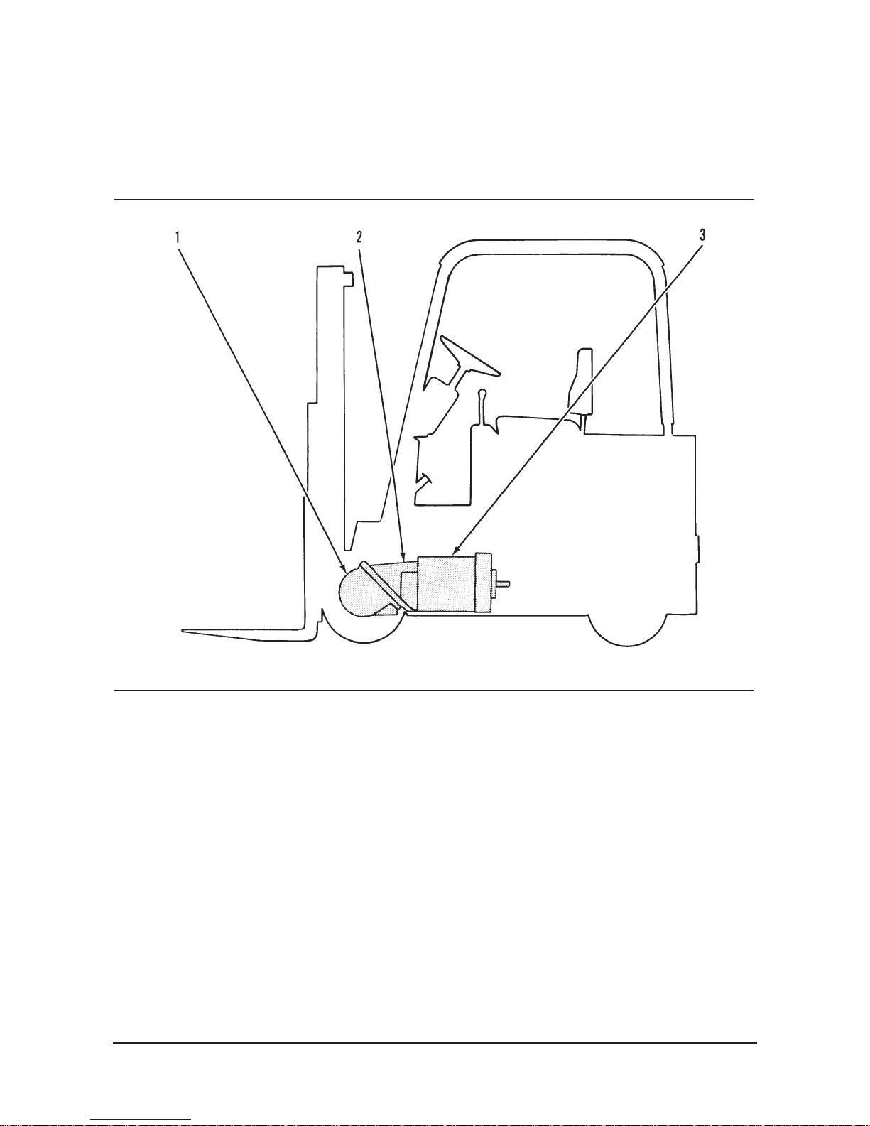
Power Flow
(1) Final drive (2) Power transfer group (3) Drive motor
5
The power train for the B, BC MODEL Lift Trucks
consists of three main components: drive motor (3),
power transfer group (2) and final drive (1).
Electric storage batteries are used as a power source
for drive motor (3). The drive motor turns power
transfer group (2). The power is sent through the
power transfer group to the axles. The axle turns final
drive (1), which is part of the drive wheels.
Page 7
Power Train Systems Operation6
Drive Motor
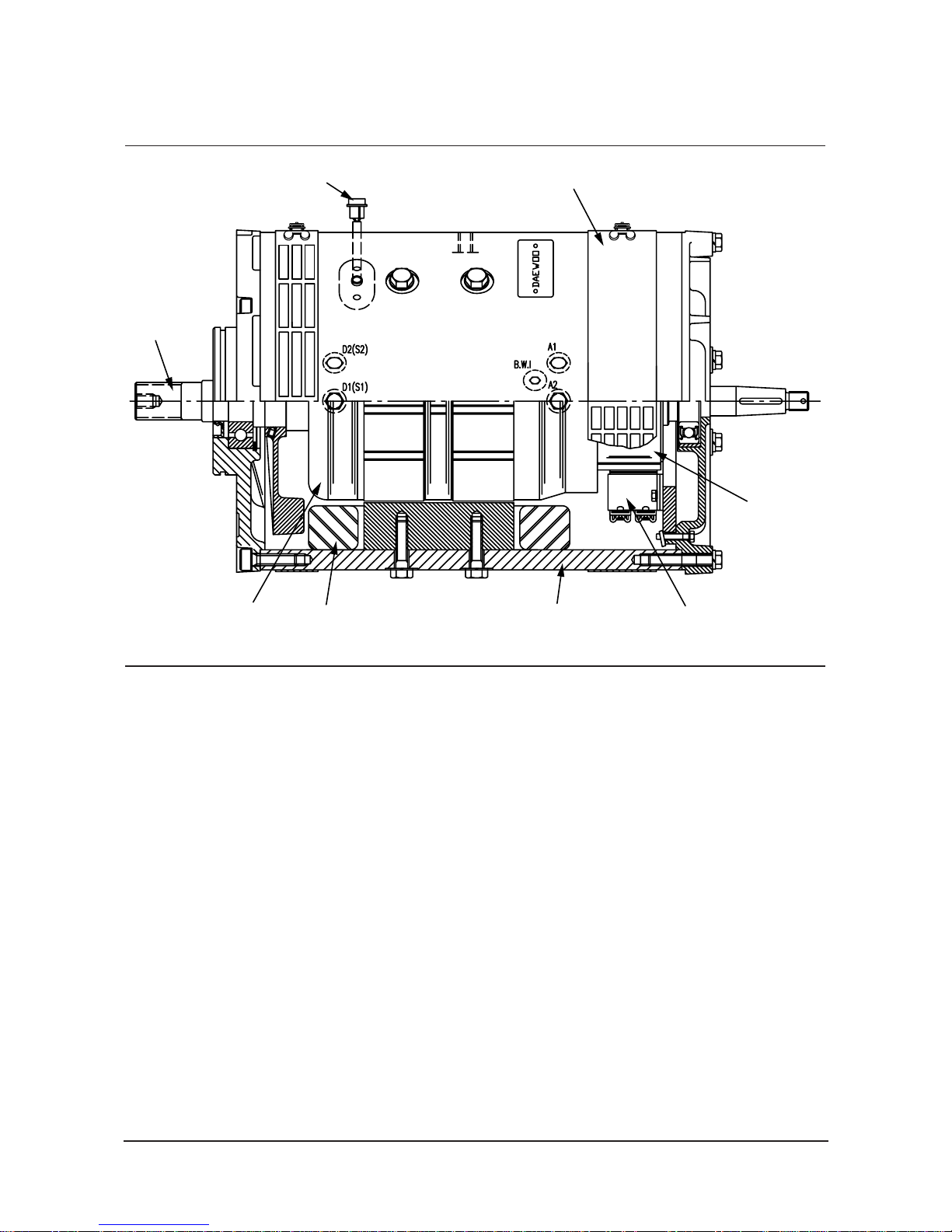
Drive Motor
(1) Shaft. (2) Cover. (3) Thermal switch (thermostat). (4) Commutator. (5) Armature assembly. (6) Field coils. (7) Frame.
(8) Brush holder.
1
32
4
8765
The drive system is operated by a direct current (DC)
motor. Electric storage batteries are the source of
power for the DC motor.
The drive motor is a series wound motor and uses a
high temperature insulation. A series wound motor is
a commutator motor. The field and armature circuits
are a series, which provides a single path for the current. Armature (5) is mounted with single row ball
bearings at each end. The ball bearings are permanently lubricated with a high temperature lubricant.
The electrical connections to the motor are made at
corrosion resistant terminals on motor frame (7). On
the outside of the motor frame is cover (2) that can
be removed for easy access to the brushes and the
commutator. Field coils (6) are fastened to the inside
of the motor frame.
The four motor brushes are held in four brush holders (8). A spring holds each of the brushes against
commutator (4) as the brushes wear.
The Optional Superior (S) function equipped lift
truckÕs drive motor is protected from overheating by a
thermal switch (thermostat) (3). The thermal switch
opens at 150
L 6¡C (302 L 11¡F). It closes at 130 L 7¡C
(266 L 13¡F). When the normally closed thermal
switch is open, the amount of current through the
motor is limited to allow the motor to cool. The motor
has a fan for cooling.
The drive motor is activated when the parking brake
is released, the key and seat switch are closed, a
direction is selected and the accelerator pedal is
depressed.
The drive motor powers the power transfer group
through shaft (1).
Page 8
Power Train Systems Operation7
Power Transfer Group
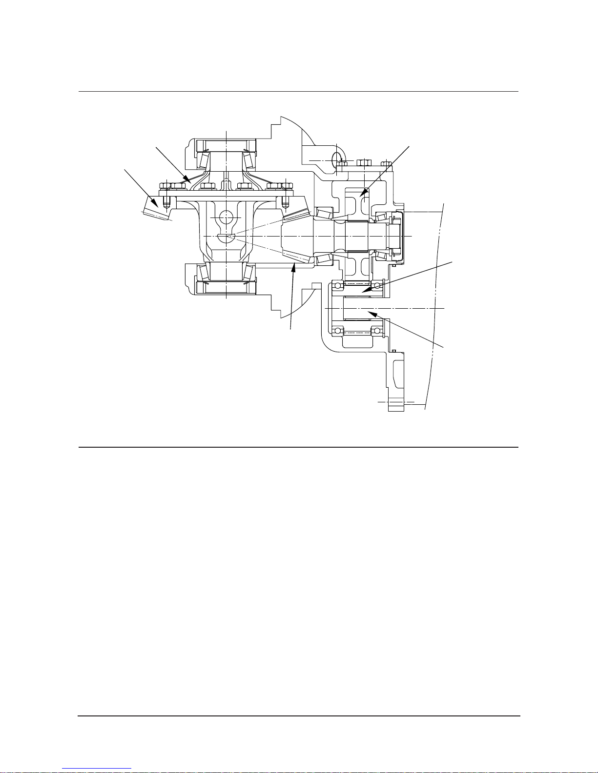
Power Transfer Group
(1) Bevel gear (2) Differential case (3) Helical gear (4) Spiral hypoid pinion (5) Input Gear (6) Drive Motor Shaft
1
2
3
5
6
4
The power transfer group is mounted under the
frame in the front of the lift truck. ItÕs a double reduction unit with the final reduction through spiral hypoid
pinion (4) and bevel gear (1).
Power for the transfer group comes from the electric
drive motor through the input gear connected with
the Drive Motor Shaft (6) through the spline . The
input gear (5) turns helical gear (3) that is mounted
on the shaft of the hypoid pinion (4).
The hypoid pinion is engaged with bevel gear (1)
which is mounted to differential case (2).
Differential case (2) has two pinion gears that are
engaged with two side gears. The side gears turn the
axle shafts.
The power transfer group is used to send the power
from the electric drive motor to the wheels. When
one wheel turns slower than the other, the power
transfer group lets the inside wheel stop or turn slower in relation to the outside wheel.
When the truck is moving straight in a forward direction with the same traction under each wheel, there is
equal torque on each axle. This holds (stops) differential pinion gears which give the same effect as if
both wheels were on the same axle. During a turn,
the force (traction) that is on the drive wheels is different. These different forces are also felt on opposite
sides of the power transfer group and cause differential pinion gears to turn. The rotation of differential
pinion gears stops or slows the inside wheel and lets
the outside wheel go faster. This moves the machine
through a turn under full power.
The power transfer group gets lubrication from oil
thrown about inside the housing, by the rotating
gears.
Page 9
Power Train Systems Operation8
Final Drive
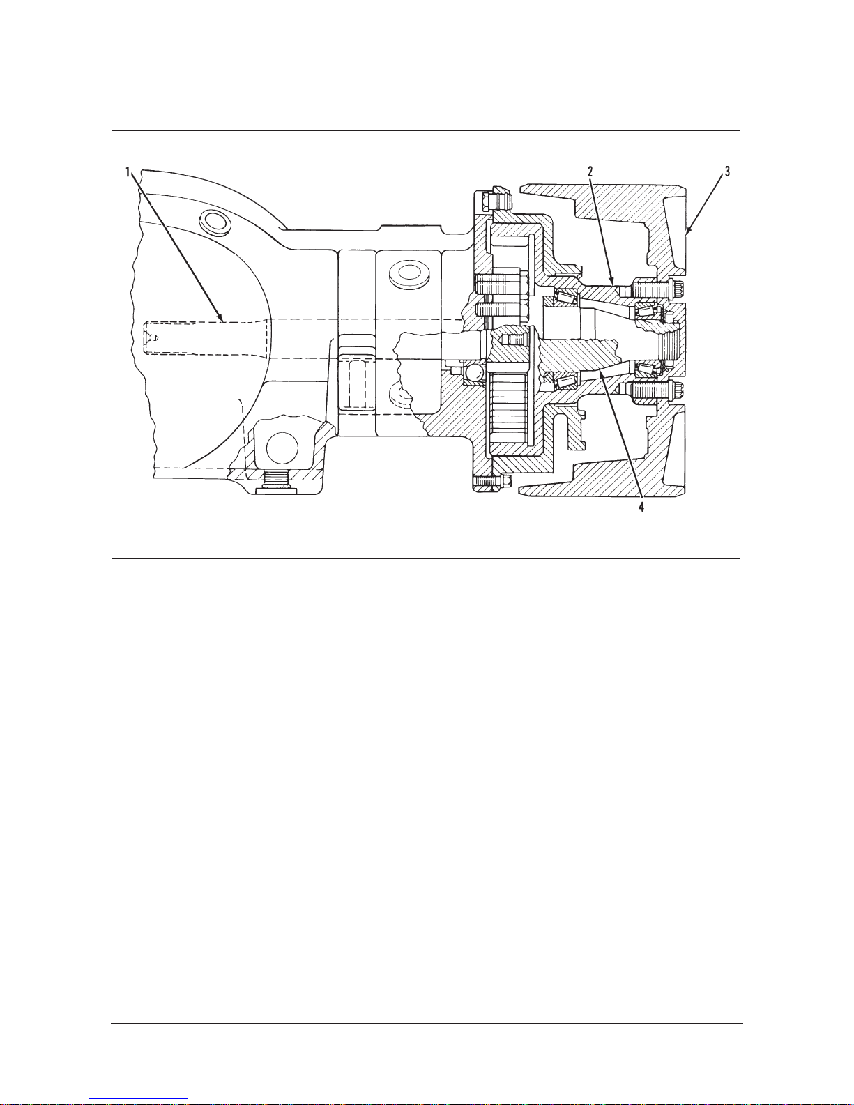
Final Drive
(1) Axle shaft (2) Hub (3) Drive wheel (4) spindle
The power transfer group turns axle shaft (1). The
gear teeth on the end of axle shaft (1) engage the
gear teeth of hub (2). The gear teeth of hub (2) are
on the inside diameter of the hub, which causes the
rotation of the hub to be the same as the axle shafts.
The reduction in size between the axle shaft and the
hub causes the hub to turn at a slower speed.
Spindle (4) is fastened to the truck frame and is used
as a support for hub (2).
Drive wheel (3) is fastened to hub (2) and turns with
the hub.
The final drive is a grease lubricated unit.
Page 10

Power Train Testing And Adjusting
Troubleshooting
Visual Checks
Make a visual inspection of the truck to check for
problems. Operate the truck in each direction.
Make a note of the noises that are not normal and
find their source. If the operation is not correct, make
reference to the Check List During Operation for
ÒProblemsÓ and ÒProbable CausesÓ.
Checks During Operation
Drive Motor
Before an analysis is made of any electric drive
motor problem, always make reference to the
Troubleshooting section of the MicroController
System Operation module.
The lift truck can move suddenly. Battery voltage
and high amperage are present. Injury to
personnel or damage to the lift truck is possible.
Safely lift both drive wheels off the floor. Put wood
blocks or jack stands of the correct capacity under
the frame so the drive wheels are free to turn.
During any test or operation check, keep away
from the drive wheels. The head capacitor (HEAD
CAP) will have to be discharged before any
contact with the control panel is made. Disconnect
the battery and discharge the HEAD CAP. Rings,
watches and other metallic objects should be
removed from hands and arms when
troubleshooting the MicroController control
system.
To prevent personal injury, never use air pressure
that is more than 205 kPa (30 psi), and wear
protective clothing and a face shield.
NOTICE
To prevent damage to electrical components, make
sure the air line is equipped with a water filter when
they are cleaned with air.
If an electrical failure or an overload of the motor
is present, personnel must not breathe the toxic
fumes which are a product of the burnt insulation.
All power must be disconnected from the motor
before any inspection is made to find the failure.
The area around the motor must be well ventilated
(air flow) and the motor is to be cooled before any
repair work is done. Water must not be used on
any electric equipment because of the danger of
electrical shock. If fire is present, disconnect the
electrical power and use a carbon dioxide
extinguisher to put the flame out.
Do not operate the drive motors without a load,
as too much speed may cause damage to the
motor and injury to personnel.
Problem 1: Drive Motor Will Not Operate.
Probable Cause:
1. Switch not closed (battery connector, key switch,
seat switch, direction switch or parking brake
switch):
Close the switch. If it still does not operate, test
for power to the control panel and power flow
through each switch with a voltmeter.
2. Bad connection. Fuse bad:
Check battery connections. Check connections
at battery connector. Check fuses, drive and
logics.
Replace fuse if bad.
Check the Drive motor and control panel for
possible reasons for a bad fuse. Some causes
are:
a. Operate during too heavy transistor load, too
high current limit (C/L).
b. Operate in stall conditions.
c. Possible short circuit in drive motor, see
Probable Causes 5, 6 and 7.
3. Low battery voltage:
Check battery terminal voltage. If too low,
charge the battery.
Check all the cells for one or more that have
defects.
Check the specific gravity of each cell. The
maximum density difference from the highest to
the lowest cell must not be more than. 020 SG
(specific gravity).
WARNING
WARNING
9
Page 11

Power Train Testing And Adjusting
4. Control panel operation not correct:
See the MicroController System Operation
module.
5. Brushes are worn:
Inspect the drive motor commutator for burnt
marks or scoring (scratches). Make corrections
or make a repair of the armature commutator
and replace the brushes as necessary.
See Armature Commutator Inspection and
Brush Inspection in Testing And Adjusting.
Make reference to Problem: Sparks At The
Commutator And/Or Rapid Brush Wear.
6. Check for opens in the field coils:
Test coils according to procedures in Testing
And Adjusting. If there are opens, make a
replacement of the field assembly.
7. Check for a short circuit in the armature windings:
Loose field winding pole pieces, make the
necessary corrections.
Field armature bar insulation.
Repair or rebuild the insulation or make a
replacement of the armature.
8. Static return to off circuit actuated:
If the static return to off is actuated, the control
will not start again until the accelerator is
released and the directional control lever is
returned to neutral.
Problem 2: Traction will not operate through a
normal work period, but hydraulic operation is
normal.
Probable Cause:
1. Brakes have a defect, cause a resistance (lack of
free movement). Heat increases, which causes the
motor to stall:
Check the brake adjustment according to the
procedures in Testing And Adjusting in the
Vehicle Systems module.
2. Too much heat in MicroController control panel
because:
a. Extra heavy traction loads.
Decrease the duty cycle load.
b. Faulty thermal switch.
See the MicroController System Operation
module.
c. Too high current limit (C/L) setting.
Lower the setting on the C/L adjustments.
These can cause transistors to become defective,
control panel failure or drive fuse to go bad.
Problem 3: Neither traction or hydraulic will last
through a complete normal work period.
Probable Cause:
1. Too small a battery equipped in the lift truck:
Use a larger battery for the complete work cycle
and normal work period.
2. Battery not being fully charged or equalized during
the battery charging operation:
Check the battery cells for an equalization
charge (a charge to make the specific gravity
the same in all cells). Check the battery charger
for defects.
3. Battery change interval is too long or changed
battery cooling time is too short. This decreases
the capacity and the ability of the battery:
Decrease the battery work duration before a
change. Increase the battery cooling time after
a charge before it is put to use.
4. Battery has one or more defective cells which
results in less than the rated capacity and ability of
the battery:
Replace the battery.
5. Traction system draws (make a consumption of)
too much battery power because of traction
system faults. Operation of the duty cycle
(complete working cycle) condition is not correct:
Check the brake adjustment according to the
procedures in Testing And Adjusting in the
Vehicle Systems module, Check the mechanical
components such as wheel bearings, axles,
etc., for corrections to eliminate the faults.
Change to a tire with less friction.
6. Hydraulic system draws too much battery power
because of lifting and tilting arrangements, or
hydraulic conditions are not correct for the duty
cycle:
Decrease hydraulic relief valve setting to the
capacity that only will be used.
Change to a smaller hydraulic pump.
Check the mast for restriction during operation.
7. Lift truck working more than the capacity of its
design with no available power after one work
shift:
Have available an extra (exchange) battery.
Decrease the speed and work load required to
complete the work shift.
10
Page 12

Power Train Testing And Adjusting
Problem 4: Sparks at the commutator and/or
rapid brush wear.
Probable Cause:
1. Worn brushes:
Make a replacement of the brushes. See New
Brush Installation And Brush Inspection in
Testing And Adjusting.
2. Overheating (too much heat) of the traction motor:
Check for an overload motor or a motor with
defects. See Armature Commutator Inspection
in Testing And Adjusting.
Decrease the current limit (C/L) adjustments if
set too high. See the MicroController System
Operation module.
Test the plugging rate, if set too short it will
cause arcing and wear at the brushes.
The duty cycle is too heavy, change the duty
cycle.
3. Defective drive motor:
See Armature Commutator Inspection in Testing
And Adjusting.
a. Commutator bars burnt in two or more positions at
180¡ apart because:
(1) Armature bars open.
Make a replacement of the armature.
(2) Motor was stalled against a heavy load while
power discharged and caused the two bars, in
contact with the brushes, to burn.
NOTICE
Too heavy a load can stall the motor, and result in a
failure to the drive motor.
(3) Short circuit in the armature.
See Armature Tests in Testing And Adjusting.
(4) Armature not in balance, out of round, off center
or with high commutator bars. This causes the
brushes to bounce (move up and down).
Make sure the diameter is the same all the way
around and is in center line with the shaft. See
Specifications.
b. Dirty motor that has a metallic or carbon dust. this
dust is a conductor which causes electrical shorts,
increase amp draw and decrease drive motor
output:
Remove any dirt with air pressure.
c. Brush movement causes arcing and brush wear:
Check the brush springs for cracks, and
overheat signs (blue).
Compare spring force with a new brush spring.
Check the brush holder for oversize (larger size
than for brush).
Replace the brush spring if necessary.
d. Loose brush leads or motor bus bar connections.
Loose cable connections at motor terminals.
Results are:
(1) High resistance and heating.
(2) Faster brush wear.
Check brushes for tight-connections.
Replace the brushes if leads are loose in
brush material. Check all cable and wire
connections for tightness.
e. Wrong grade of brushes installed that are not
adaptable to the motor:
Make sure all the brushes are of DAEWOO
standards. Do not use other brands of brushes.
f. Possibly heavy working condition that causes too
much motor heat and rapid brush wear:
Make a replacement of the brushes and make
sure the brushes are seated. See New Brush
Installation and Brush Inspection in Testing And
Adjusting.
Check the brush springs for the correct
installation and for the correct spring usage. Too
strong a spring rate will increase amperage
draw and brush wear rate.
Prevent operation in stall condition. Excessive
(too much) duty cycle which increases motor
temperatures and rapid brush wear.
4. Overload of the drive motor such as: towing loads,
constant ramp operation, chiseling (hydraulic
actions that are not practical) loads and dragging
(pull or push loads on the ground) loads:
Operator training for better working practices.
Add an auxiliary cooling to the drive motors.
5. Current limit (C/L) set too high that causes too
much current consumption through motors in the
transistor range:
Decrease the current limit (C/L) adjustment to
the correct setting, see the MicroController
System Operation module.
6. Drive motor, armature or field windings have a
defect that results in high current draw at low
torque output:
See Armature Tests and Field Coil and Terminal
Tests in Testing And Adjusting.
11
Page 13

Power Train Testing And Adjusting
7. Restriction caused by components:
Correct and make adjustments to wheel brakes
and parking brakes that drag.
Make changes to tires with less restriction.
Check and correct wheel bearing torques.
Problem 5: Low resistance to ground [battery
polarity either positive (+) or negative (-) or a
medium voltage is in direct contact with truck
frame (body) or drive motor body].
Probable Cause:
1. Dirty battery, electrolyte on top of cells and is in
contact with the frame. Current flows through
battery box, which places a voltage on the truck
frame:
Clean the battery with baking soda and water
solution.
2. Battery or control panel wire connections in
contact with truck frame:
Make a continuity test and move the wire from
contact.
Remove wires in sequence until the fault is
cleared.
The fault will be in the wire last disconnected.
3. Dirty motor:
Remove metallic or carbon dust with air
pressure.
4. Wet motor:
To dry the motor, heat it to 90¡C (194¡F).
Problem: 6. Commutator surface has groove or
extra wear.
Probable Cause:
1. Brushes are worn too low, brush wires caused
arcing on the commutator:
Replace the brushes. See Brush Inspection in
Testing And Adjusting and the method to make
the Brush Lift Estimate in Testing And Adjusting.
2. Dirty motor; and possibly salt water got inside:
Disassemble motor, remove the debris with air
pressure. If necessary, dry the motor with heat
to 90¡C (194¡F)
3. Grades of brushes mixed:
Make sure all the brushes are of DAEWOO
standards. Do not use other brands of brushes.
Problem 7: Lift truck moves faster in one
direction than the other direction with the same
amount of accelerator pedal movement in Bypass
mode (speed).
Probable Cause:
1. Motor brushes not located in the correct electrical
position (brush neutral settings):
If the holes in the brush holder are not
extended, make them longer so that brush
holder can have a little rotation. When the
holder is in the correct position, lift truck speed
will be the same in both directions.
2. One directional contactor worn more than the
other or loose connection on one contactor:
Check contactor for wear and tighten any loose
connections.
Problem 8: Lift truck will not get to top speed.
Probable Cause:
1. Battery not fully charged or battery has bad cells:
Charge the battery. Check for bad cells.
Replace battery if necessary.
2. A fault either in the drive motor, control panel or
drive train:
Check lift truck speed in both directions. If the
MicroController panel needs tuned up, make
adjustments as shown in the respective
MicroController System Operation module. If
the drive motor is at fault, make the tests of the
motor components in Testing And Adjusting.
Problem 9: Lift truck does not have enough
power to position itself under a load. Lift truck
does not have enough power on ramps or towing
trailers.
Probable Cause:
1. Current limit (C/L) set too low:
Set current limit (C/L) to specification in the
MicroController System Operation module.
12
Page 14

Power Train Testing And Adjusting
2. Current limit (C/L) circuit has a defect:
Make test to the MicroController control panel as
stated in the respective service module. Repair or
replace components as necessary.
3. Unpolished or improperly positioned forks:
Install tapered and polished forks. Position forks
correctly for load being lifted.
4. Lift truck equipped with tires that have poor
traction:
Install tires that have good traction per
recommendation from DAEWOO Inc.
5. Lift truck work load is too heavy or the duty cycle
too long:
Decrease the work load and/or duty cycle.
Problem 10: Lift truck has slow acceleration:
Probable Cause:
1. Drive control overheated and the thermal switch
opens:
NOTE: The lift truck will still go into the bypass
mode, but current limit will be cut back in the
transistor mode if the thermal switch opens.
Allow the MicroController control panel to become
cool so the thermal switch will close.
NOTE: The thermal switch will open circuit if the
temperature is 150 L 6¡C (302 L 11¡F) and reclose
(short circuit) at 130 L 7¡C (266 L 13¡F).
Power Transfer Group and Final Drive
Problem 1: Constant noise in drive axle housing.
Probable Cause:
1. Lubricant not to the specified level.
2. Wrong type of lubricant.
3. Wheel bearings out of adjustment or have a defect.
4. Bevel gear and pinion not in adjustment for correct
tooth contact.
5. Teeth of bevel gear and pinion have damage or
wear.
6. Too much or too little pinion to bevel gear
clearance (backlash).
7. Loose or worn drive motor bearings.
8. Loose or worn side bearings.
9. Noise in the drive wheel reduction components.
Problem 2: Noise at different intervals.
Probable Cause:
1. Bevel gear does not run evenly.
a. Nut on drive gear not tightened correctly.
b. Drive gears have a defect (warped).
2. Loose or broken bearings.
3. Failure of or not enough lubricant on the drive
wheel reduction components.
Problem 3: One drive wheel does not turn (motor
operates).
Probable Cause:
1. Broken axle shaft.
a. Loose wheel bearings.
b. Loose flange studs or nuts.
c. Bent housing.
2. Pinion gear teeth have damage.
3. Bevel gear, pinion or gears broken.
Problem 4: Leakage of lubricant.
Probable Cause:
1. Loss through axle shafts.
a. Lubricant above specified level.
b. Wrong kind of lubricant.
c. Restriction of axle housing breather.
d. Axle shaft oil seal installed wrong or has
damage.
2. Loss at pinion.
a. Lubricant above specified level.
b. Wrong kind of lubricant.
c. Restriction of axle housing breather.
d. Drive motor seal worn or not installed correctly.
13
Page 15
Power Train Testing And Adjusting
Drive Motor
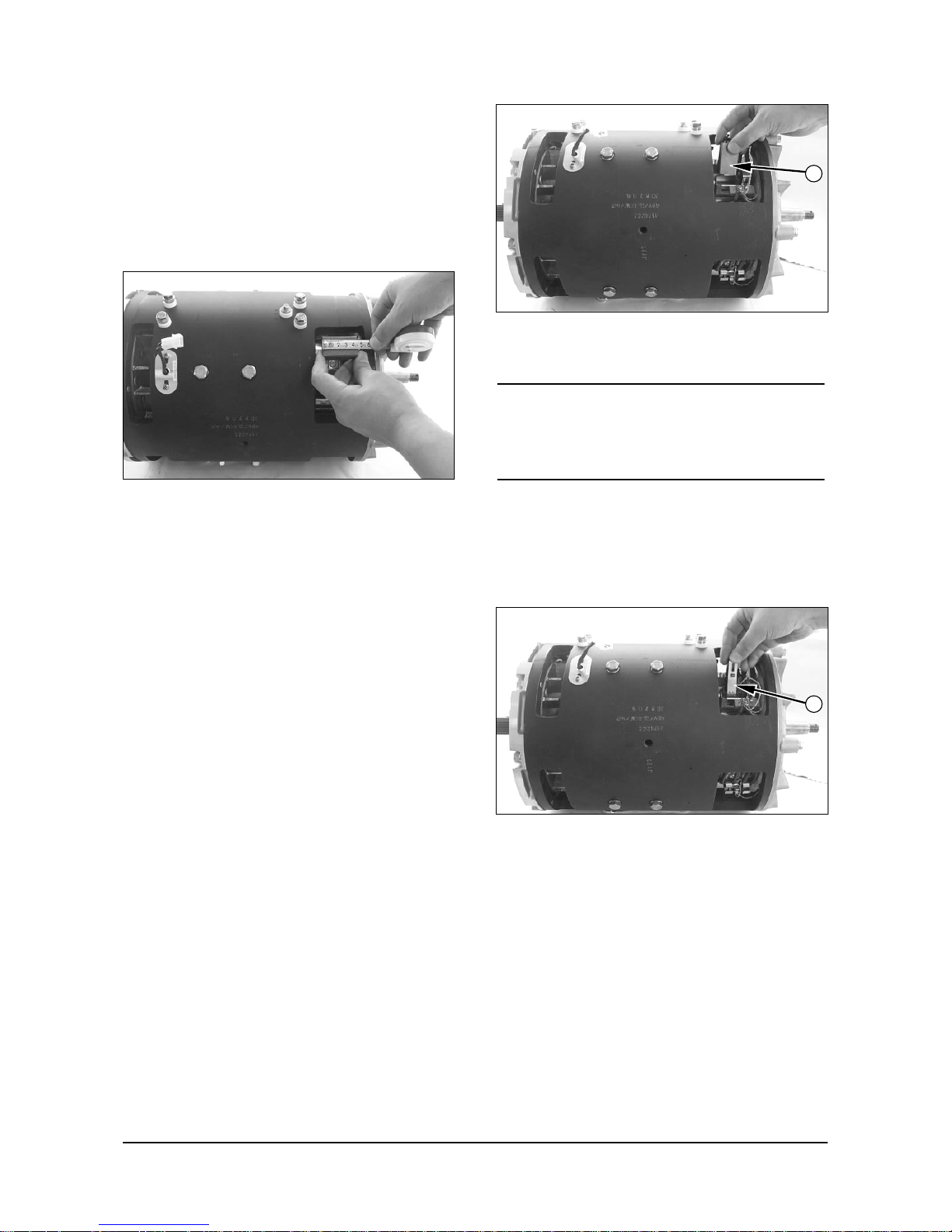
Motor Brushes
Brush Inspection
1. Measure the brush material on the longest side.
Brush Measurement
2. If the brush length is less than 19 mm (.75 in) on
the longest side, replace the brushes.
New Brush Installation
NOTE : Installation of new brushes is a two person
operation.
1. Disconnect the batteries and remove them from
the lift truck. Put the batteries close enough to the
truck that the battery connector can be plugged in.
2. Lift the truck and put blocks under it so that the
drive wheels are off the ground. Put blocks in front
and in back of the steering wheels.
3. Discharge the head capacitor.
4. Remove the commutator screen cover remove old
brushes.
Install Brushes
(1) Brushes.
NOTICE
Installation of the wrong brushes can cause early
motor failure. Always make sure the correct DAEWOO
brushes are installed.
5. Install new brushes(1). Make sure the brushes
move freely in the brush holders. Use a piece of
plain bond paper to remove brush material if there
is a restriction of brush movement.
Install Springs
(2) Spring.
6. Place carefully the brush spring(2) on the top of
brush and make sure they fasten into the brush
holder box.
7. Pull up on the two wires of each brush until the
contact end of the brush moves away from the
commutator. Release the wires to see if the brush
moves smoothly back into contact with the
commutator. If it is too difficult to pull out, or it does
not move smoothly in the brush holder box,
remove the spring and brush. Make an inspection
to find and correct the cause of the problem.
8. Connect the batteries to the battery connector.
14
1
2
Page 16

Power Train Testing And Adjusting
Wear eye protection when seating, polishing or
cleaning the motor with air pressure. During the
seating and polishing procedure, keep fingers
away from components in rotation. For prevention
of injury to fingers, do not use a commutator
cleaner or brush seater stone that is shorter than
63.5 mm (2.50 in.).
Brush Seating
(3) ZLX Ð0036 Brush seater stone.
9. Put ZLXÐ0036 Brush Seater Stone (3) on the
commutator and operate the motor at a slow
speed.
NOTICE
Do not let stone (3) stay in contact with the commutator
bar too long. This causes more wear than is necessary
to the brushes and the commutator.
10. Move stone (3) across the commutator at the
backe edge of the brushes for a short time. This
will take the shiny finish off the commutator and
seat the new brushes.
11. Turn the key switch to the OFF position and
disconnect the batteries. Check the contact
surface of each brush. At least 85% of the brush
contact surface of each brush must show wear. If
necessary, do Steps 8 through 11 again until the
correct wear can be seen on the brush contact
surface.
NOTICE
Never use air pressure that is more than 205 kPa (30
psi). Make sure the line is equipped with a water filter.
12. After the brushes have the correct seat contact
surface, operate the motor at slow speed. Use
compressed (pressure) air to remove all dust and
abrasive grit.
Armature Tests
Test For Short Circuit
Short Circuit Test
(1) Growler. (2) Armature. (3) Hacksaw blade.
(4) Green light. (5) Red light.
1. Put armature windings (2) in the jaws of growler.
(3).
2. Turn the growler (1) on. Slowly turn the growler on
the armature (2) while a hacksaw blade (3) is held
over the windings.
3. If the windings are shorted, the green light (4) will
be on. The red light (5) will be on if the windings
do not have a short.
The odor of burned insulation from the drive motor
while it is in operation is an indication of a short in
the armature.
Tools Needed
Digital Multimeter Or Equivalent 1
Growler Tester 1
WARNING
15
3
5
3
2
4
1
Page 17

Power Train Testing And Adjusting
Ground Test
Ground Test.
A digital multimeter can also be used to test for
grounds. Put the Function/Range Switch on the 2M
resistance (½) scale. When the test probes are put
on the commutator and the shaft, the meter must
give an indication of over load (OL). This means that
the resistance is more than 2 megohms.
NOTICE
Never use air pressure that is more than 205 kPa (30
psi). Make sure the air line has a water filter.
If there is an indication of a ground in the above test,
remove any dirt or debris form the armature with
compressed (pressure) air.
Do the test for grounds again. If there is still an
indication of a ground, make a replacement of the
armature.
Open Circuit Test
Open Circuit Test
1. Put the digital multimeter Function / Range Switch
on the 200 ohm resistance (½) scale.
2. Put one test lead on one commutator bar. Put the
other test lead on an adjacent (next to) bar and
there must be less than one ohm resistance.
This test can also be done with an instrument,
such as a Kelvin Double Bridge, that can make a
measurement of very low resistance. Do the test
the same as above and make a comparison of the
resistance measurements.
Two burned areas on opposite sides of the
commutator are indications of an open armature
winding. These burned areas can cause very rapid
brush wear.
16
Page 18
Power Train Testing And Adjusting
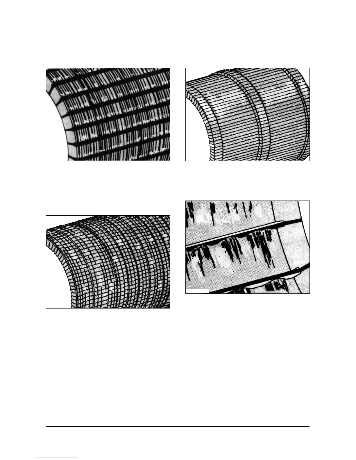
Commutator Inspection
Surfaces of Commutators that need Replacement
Marks on the Commutator Surface
Marks on the commutator surface are an indication
that metal has moved from the commutator surface
to the carbon brushes. Marks will cause fast brush
wear.
Threads on the Commutator Surface
Threads (grooves that look like threads) on the
commutator surface, will also cause fast brush wear.
Grooves on the Commutator Surface
Grooves on the commutators surface are caused by
a cutting material in the brush or atmosphere.
Copper Drag on the Commutator Surface
Copper drag is an extra amount of commutator
material at the back edge of the commutator bars.
17
EHPS009B
EHPS010B
EHPS012B
EHPS011B
Page 19

Power Train Testing And Adjusting
Pitch BarÐMarks on the Commutator Surface
Pitch barÐmarks cause low or burnt marks on the
commutator surface.
Field Coil and Terminal Tests
Open Circuit Test
Open Circuit Test
1. Put the digital multimeter Function/Range Switch
on the 200 ohm resistance (½) scale.
2. Put one test probe to each outer field terminal
(S1,S2).
3. The resistance must be less than one ohm. If the
resistance is too high, it is an indication of
corrosion on the terminals or an open field coil.
Ground Test
Ground Test
(1) Field Terminal. (2) Motor housing.
1. Put the digital multimeter Function/Range Switch
on the 20M resistance (½) scale.
2. Put one test lead to either outer field terminal (1)
and the other test lead to the motor housing (2).
There must be more than one megohm resistance.
3. If there is a measurement of less than one
megohm, it can be caused by wet insulation on the
field windings or excessive brush dust in housing.
Heat the motor at 88°C (190°F) until the resistance
goes above one megohm. If the resistance does
not go above one megohm, the shell and field
assembly must be replaced.
Tools Needed
Digital Multimeter Or Equivalent 1
18
EHPS013B
1
2
Page 20

Power Train Testing And Adjusting
Armature Terminal Test
Test for Continuity
Brush Test
1. Put the digital multimeter Function/Range Switch
on the 200 ohm resistance (½) scale.
2. Put one test lead to an outer armature terminal
and the other test lead to each brush lead that
connects to that terminal. There must be less than
one ohm resistance.
3. Do Step 2 again with the other outer armature
terminal and brush leads.
4. Too much resistance is an indication of corrosion
at the connection to the terminal.
Ground Test
Ground Test
(1) Armature Terminal. (2) Motor Housing.
1. Put the digital multimeter Function/Range Switch
on the 20M resistance (½) scale.
2. Put one test lead to an outer brush terminal (1)
and the other test lead to the motor housing (2).
There must be more than one megohm resistance.
3. Do the test again with one test lead on the other
outer brush terminal.
Brush Holder Test
Brush Holder Test
(1) Brush Holder. (2) End Bell.
1. The brush holders are mounted on the rocker at
the commutator end of the motor. Make a visual
inspection of the brush holders and the rocker.
2. Put digital multimeter Function/Range Switch on
the 200 ohm resistance (½) scale. Put one test
lead to a brush holder (1) and the other test lead
to the end bell (2). The meter must show overload
(OL).
3. Check each brush holder. If meter reading is low,
the brush holder is grounded. Replace the rocker.
Tools Needed
Digital Multimeter Or Equivalent 1
Tools Needed
Digital Multimeter Or Equivalent 1
19
2
1
2
1
Page 21

Power Train Testing And Adjusting
Thermal Switch Tests
Open Circuits Test
Open Circuit Test
1. Put the digital multimeter Function/Range Switch
on the 200 ohm resistance (½) scale.
2. Put one test lead to each side of the thermal
switch harness.
3. The resistance must be less than one ohm.
Ground Test
Ground Test
1. Put the digital multimeter Function/Range Switch
on the 20M resistance (½) scale.
2. Put one test lead to either of the plug prongs. The
other test lead must be grounded to the motor
housing.
There must be more than one megohm resistance.
Brush Life Estimate
1. Before installation of new brushes, make an
inspection of the armature commutator, see
Armature Commutator Inspection in Testing and
Adjusting.
2. Do the steps and procedures for New Brush
Installation in Testing and Adjusting.
3. Make the initial (first) inspection of brush wear
between 250 smh and 500 smh. The reason for
this initial inspection is to see if the brush wear
rate is normal and not too fast. The measurement
will help make an estimate of the length of brush
life to be expected.
NOTE : If there is an indication that brush wear is too
fast, see Troubleshooting, Problem: Sparks
at the commutator and/or rapid brush wear;
for probable causes of this problem.
4. Inspect all brushes in the motors. Measure and
record each brush length (see Specification for
each new brush length and minimum brush length).
5. Estimate expected brush life (hours). Use the
shortest measurement from Step 4 and the
following Sample Procedure:
Length of new brush ................45.8 mm (1.803 in.)
Minimum length of brush...............19 mm (0.75 in.)
New brush length [45.8 mm (1.803 in.)] - Minimum
brush length [19 mm(0.75 in.)] = Total amount of
usable brush wear [26.8 mm(1.055 in.)].
Length of shortest brush at 500 smh is 43.3 mm
(1.703 in.).
New brush length [45.8 mm (1.803 in.)] - Length of
shortest brush at 500 smh [43.3 mm (1.703 in.)] =
Amount of brush wear at 500 smh [2.5 mm (.10 in.)].
Amount of brush wear at 500 smh [2.5 mm (.10
in.)]
Ö Total amount of usable brush wear [26.8
mm (1.055 in.)] = Portion of brush used at 500
smh (.1).
Service Meter Hours (smh) at brush wear
measurement (500 smh)
Ö Portion of brush
used (.1) = Approximate total brush life of a new
brush (5000 smh).
Approximate total brush life of a new brush
(5000smh)ÐAmount of smh at brush life estimate
(500 smh) = Remainder of usable brush life
(4500 smh).
Tools Needed
Digital Multimeter Or Equivalent 1
20
Page 22

Power Train Testing And Adjusting
6. The smh estimate of brush life can be used if the
machine is to work at the same rate (duty cycle),
the battery is not discharged too much or the
battery cells have not become damaged. If the
machine is made to work harder, the battery is
discharged too much, or the battery cells become
damaged, the motor temperature will get hot very
fast. This will cause rapid wear of the brush.
7. It is important to check brush length and brush
condition at a specific time, such as during the
preventive maintenance check. If an inspection
shows that brush life will not extend to the next
preventive maintenance check, install new
brushes.
Power Transfer Group
Adjustments
Power Transfer Group
Power Transfer Group
(1) Bevel gear. (2) Pinion gear. (3) Shim pack. (4) Bearing
cup.
Bevel gears and pinions are available in sets that are
machined for each other and must never be installed
separately. The same identification mark of letters
and numbers is put on both the pinion and bevel
gear. Make sure they have the same identification
mark before going to the procedures that follow.
The distance from the centerline of bevel gear (1) to
the flat end of pinion (2) is 78.0 mm (3.071 in.). The
end of each pinion has a mark of either a plus (+)
number, a minus (-) number, or zero (0). These
numbers indicate the position where each gear set
runs best. The dimension is controlled by shim pack
(3) behind inner bearing cup (4).
If a pinion has a mark of (+.10), it needs 0.10 mm
(0.004 in.) less shims than a pinion with a mark of (0).
This increases the distance from the centerline of the
bevel gear to the end of the pinion to 78.1 mm (3.075
in.). This increase of 0.10 mm (0.004 in.) is the
meaning of a (+.10) mark on the pinion. If the pinion
has a mark of (-.10), it needs 0.10 mm (0.004 in.)
more shims than a pinion with a (0) mark. This
reduces the dimension from the centerline of the
bevel gear to the end of the pinion to 77.9 mm (3.067
in.).
1
2
4
3
ID MARKS
21
Page 23

Power Train Testing And Adjusting
Pinion Installation
Pinion Configuration
(2) Shim pack. (3) Bearing cup. (4) Bearing cup.
(5) Bearing cone. (6) Pinion gear. (7) Bearing cone.
(8) Locknut. (9) Ring. (10) Gear. (11) Ring.
NOTE: The adjustment procedures that follow only
cover the shim set configuration. Look for additional
service publications to provide more detailed
information on the change.
22
Page 24

Power Train Testing And Adjusting
1. If the original bevel gear and pinion set is to be
used again, measure old shim pack (2) and make
a new shim pack the same thickness. If a new
bevel gear and pinion set is used, refer to the
Pinion Shim Chart for the amount that the original
shim pack should be changed.
If three or more shims are used, the smaller shims
are to be put in the center of the shim pack.
EXAMPLE: If the old pinion has a mark of (+.06) and
the new pinion has a mark of (-.08) add 0.14 mm
(0.006 in.) shims to the original shim thickness.
2. Install bearing cups (3) and (4) with new shim
pack (2) behind bearing cup (3). Install bearing
cone (5) on pinion shaft (6).
3. Put the pinion shaft assembly into the housing and
install bearing cone (7) and nut (8). Tighten nut (8)
to a torque of 15 to 34 N¥m (11 to 25 lb¥ft) while
rotating the pinion.
4. Measure the distance from the centerline of the
differential bearing bores to the end of the pinion
and determine the amount of shims needed
behind bearing cup (3). See Pinion Depth Check.
5. Remove bearing cup (3) and add or remove the
required shims. Reinstall bearing cup (3).
6. Recheck pinion depth. The measured pinion depth
must be within 0.03 mm (0.001 in.) of the required
pinion depth.
7. After the pinion depth is correct, remove
Pinion Depth Gauge and the pinion shaft. Put ring
(9) on the pinion shaft and put gear (10) in position
in the housing. [NOTE: Side of gear (10) with
recessed hub must be installed next to ring (9)].
Put the pinion shaft in the housing and through
gear (10). Install ring (11) on pinion shaft (6).
8. Set pinion bearing preload. See Pinion Bearing
Adjustment.
9. Recheck pinion depth.
10. After pinion bearing preload and pinion depth are
correct, bend a tab on the lockwasher into a slot
of nut (8) to lock it in position.
23
PINION SHIM CHART
New Pinion Marking
+.10 +.08 +.06 +.04 +.02 0 -.02 -.04 -.06 -.08 -.10
+.10 0 +0.02mm +0.04mm +0.06mm +0.08mm +0.10mm +0.12mm +0.14mm +0.16mm +0.18mm +0.20mm
(0.001 in.) (0.002 in.) (0.002 in.) (0.003 in.) (0.004 in.) (0.005 in.) (0.006 in.) (0.006 in.) (0.007 in.) (0.008 in.)
+.08 -0.02mm 0 +0.02mm +0.04mm +0.06mm +0.08mm +0.10mm +0.12mm +0.14mm +0.16mm +0.18mm
(0.001 in.) (0.001 in.) (0.002 in.) (0.002 in.) (0.003 in.) (0.004 in.) (0.005 in.) (0.006 in.) (0.006 in.) (0.007 in.)
+.06 -0.04mm -0.02mm 0 +0.02mm +0.04mm +0.06mm +0.08mm +0.10mm +0.12mm +0.14mm +0.16mm
(0.002 in.) (0.001 in.) (0.001 in.) (0.002 in.) (0.002 in.) (0.003 in.) (0.004 in.) (0.005 in.) (0.006 in.) (0.006 in.)
+.04 -0.06mm -0.04mm -0.02mm 0 +0.02mm +0.04mm +0.06mm +0.08mm +0.10mm +0.12mm +0.14mm
(0.002 in.) (0.002 in.) (0.001 in.) (0.001 in.) (0.002 in.) (0.002 in.) (0.003 in.) (0.004 in.) (0.005 in.) (0.006 in.)
+.02 -0.08mm -0.06mm -0.04mm -0.02mm 0 +0.02mm +0.04mm +0.06mm +0.08mm +0.10mm +0.12mm
(0.003 in.) (0.002 in.) (0.002 in.) (0.001 in.) (0.001 in.) (0.002 in.) (0.002 in.) (0.003 in.) (0.004 in.) (0.005 in.)
0 -0.10mm -0.08mm -0.06mm -0.04mm -0.02mm 0 +0.02mm +0.04mm +0.06mm +0.08mm +0.10mm
(0.004 in.) (0.003 in.) (0.002 in.) (0.002 in.) (0.001 in.) (0.001 in.) (0.002 in.) (0.002 in.) (0.003 in.) (0.004 in.)
-.02 -.0.12mm -0.10mm -0.08mm -0.06mm -0.04mm -0.02mm 0 +0.02mm +0.04mm +0.06mm +0.08mm
(0.005 in.) (0.004 in.) (0.003 in.) (0.002 in.) (0.002 in.) (0.001 in.) (0.001 in.) (0.002 in.) (0.002 in.) (0.003 in.)
-.04 -0.14mm -0.12mm -0.10mm -0.08mm -0.06mm -0.04mm -0.02mm 0 +0.02mm +0.04mm +0.06mm
(0.006 in.) (0.005 in.) (0.004 in.) (0.003 in.) (0.002 in.) (0.002 in.) (0.001 in.) (0.001 in.) (0.002 in.) (0.002 in.)
-.06 -0.16mm -0.14mm -0.12mm -0.10mm -0.08mm -0.06mm -0.04mm -0.02mm 0 +0.02mm +0.04mm
(0.006 in.) (0.006 in.) (0.005 in.) (0.004 in.) (0.003 in.) (0.002 in.) (0.002 in.) (0.001 in.) (0.001 in.) (0.002 in.)
-.08 -0.18mm -0.16mm -0.14mm -0.12mm -0.10mm -0.08mm -0.06mm -0.04mm -0.02mm 0 +0.02mm
(0.007 in.) (0.006 in.) (0.006 in.) (0.005 in.) (0.004 in.) (0.003 in.) (0.002 in.) (0.002 in.) (0.001 in.) (0.001 in.)
-.10 -0.20mm -0.18mm -0.16mm -0.14mm -0.12mm -0.10mm -0.08mm -0.06mm -0.04mm -0.02mm 0
(0.008 in.) (0.007 in.) (0.006 in.) (0.006 in.) (0.005 in.) (0.004 in.) (0.003 in.) (0.002 in.) (0.002 in.) (0.001 in.)
Old
Pinion
Marking
Page 25

Power Train Testing And Adjusting
Pinion Depth Check
Tools Needed:
Pinion Depth Gauge (A).
Pinion Depth check
(1) Bearing cap (A) Pinion Depth Gauge
1. Put the bar and discs of tool (A) in the bearing
bores of the housing assembly as shown. Install
bearing caps (1) and tighten the bolts.
2. Measure the distance from the end of the pinion
shaft to the bottom of the bar with an inside
micrometer. Record this measurement.
3. Measure the outside diameter of the bar with an
outside micrometer. Divide this measurement by 2
and add it to the recorded measurement from Step
2. Record this total measurement. This is the
actual mounting distance.
4. Calculate the required shim thickness to add or
remove as follows: the nominal mounting
distance+deviation from nominal (as marked on the
end of the pinion, either + or - number, in
millimeters) = required mounting distance. The
actual mounting distance (from Step 3) - the
required mounting distance = required shim
thickness to add or remove (added if difference is +,
removed if difference is -).
Example:
78.00 mm (3.071 in.) - nominal mounting distance
- 0.08 mm (0.003 in.) - deviation from nominal
(marked on end of pinion)
77.92 mm (3.068 in.) - required mounting distance
78.10 mm (3.075 in.) - actual mounting distance
from Step 3
-77.92 mm (3.068 in.) - required mounting distance
0.18 mm (0.007 in.) - thickness of shims to be
added or removed
Pinion Bearing Adjustment
Tools Needed:
Pinion Bearing Preload Gauge (A)
Dial Indicator Group (B).
Pinion Bearing Preload Adjustment
(1) Shim pack (2) Bearing cone (3) Locknut (4) Pinion gear
1. Install tool (A) [or 4.0 mm (.16 in.) of shims] in
place of shim pack (1). Install bearing cone (2), the
washer, lockwasher, and nut (3). Tighten nut (3) to
a torque of 15 to 34 N¥m (11 to 25 lb¥ft.). (NOTE:
See Preload Shim Chart for shim numbers.)
2. Use tooling (B) to measure the end play of pinion
shaft (4). Record this measurement. Remove nut
(3), the lockwasher, washer, and bearing cone (2).
3. Remove tool (A) (or shims). Measure the thickness
of tool (A) with an outside micrometer (if shims
were used, measure each shim individually and
add the measurements together). subtract from
this thickness the recorded end play from Step 2.
This is the thickness of shims (1) that are needed
with no bearing preload.
24
Preload Shim Chart
Part No. Thickness
Part No. Thickness
924760 0.04 mm (.002 in.)
924761 0.08 mm (.003 in.)
924762 0.12 mm (.005 in.)
924763 0.25 mm (.010 in.)
924764 0.8 mm (.03 in.)
924765 1.6 mm (.06 in.)
Page 26

Power Train Testing And Adjusting
4. In order to get bearing preload, subtract 0.05 mm
(.002 in.) from the shim pack thickness found in
Step 3. This is the shim pack thickness that needs
to be installed.
5. Install the correct thickness of shims (1), bearing
cone (2), the washer, lockwasher, and nut (3).
Tighten nut (3) to a torque of 180 L 25 N¥m
(135 L 18 lb¥ft).
Rolling Torque Check
6. Check the rolling torque of the pinion as shown. It
must be 0.85 to 1.70 N¥m (7.5 to 15.0 lb¥in). If the
torque is not correct, add or remove shims (1) until
it is correct. Removal of shims (1) increases the
rolling torque. Adding shims (1) decreases the
rolling torque. Record the actual rolling torque after
the shims have been added or removed.
Power Transfer Group Bearing and
Gear Clearance (Backlash)
Adjustments
Tools Needed:
Dial Indicator Group (A)
Backlash Adjustment
(1) Bearing Cone. (2) Bevel Gear. (3) Bolt. (4) Bearing Cup.
(5) Bearing Cap. (7) Lockwasher. (8) Locknut.
(9) Pinion Gear.
1. Install bearing cones (1) on the differential case.
2. Put bevel gear (2) on the differential case and
tighten ten bolts (3) to a torque of 70 L 15 N¥m
(50 L 11 lb¥ft). Put bearing cups (4) on bearing
cones (1).
2
3
4
1
9
8
7
5
25
Page 27

Power Train Testing And Adjusting
Install Carrier Assembly
(5) Bearing cap (6) Bolts
3. Put the carrier assembly in position in the housing
assembly. Install bearing caps (5) and four bolts
(6).
Tighten bolts (6) to a torque of 220 L 25 N¥m
(160 L 18 lb¥ft).
4. Install lockwashers (7) and locknuts (8). Use
tooling (A) to check gear clearance (backlash)
between bevel gear (2) and pinion (9). Adjust
locknuts (8) until the clearance is 0.15 to 0.20 mm
(0.006 to 0.008 in.).
Adjust the clearance by turning one locknut (8) in
and the other locknut out an equal amount.
5. Check the rolling torque again as shown in Pinion
Bearing Adjustment, Step 6. Tighten locknuts (8)
equally to preload the differential case bearings.
Proper bearing preload will increase the rolling
torque at the pinion (recorded in Pinion Bearing
Adjustment, Step 6) by 0.63 to 0.88 N¥m (5.6 to
7.8 lb¥in).
6. Measure backlash again. After backlash and
preload are correct, bend a tab on each
lockwasher (7) into a slot in locknuts (8) to hold
them in position.
Correct Tooth Contact Setting
7. Check the tooth contact pattern as follows. Check
the tooth contact setting between the bevel gear
and pinion after the gear clearance (backlash) and
bearing preload adjustments have been made as
follows.
a. Put a small amount of Prussian blue, red lead or
paint on the bevel gear teeth. Turn the pinion in
both directions and check the marks made on the
bevel gear teeth.
Short Toe Contact Setting
b. With no load, correct tooth contact setting will be
as shown. The area of contact starts near the toe
of the gear and goes 30 to 50% up the length of
the tooth.
With this setting, when a load is put on the gear,
the load will be over the correct area of the teeth.
26
Page 28

Power Train Testing And Adjusting
Short Heel Contact Setting
c. If bevel pinion shaft is too far away from bevel
gear, short toe contact will be the result as shown.
The teeth of pinion will be in contact with toe ends
of convex faces (part that makes a curve toward
the outside), and top edge of heel end of concave
faces (part that makes a curve toward the inside).
To correct this, add shims under pinion bearing
cup. After this is done, check gear clearance
(backlash) and tooth contact again.
d. If bevel pinion shaft is too near to center of bevel
gear, short heel contact will be the result as
shown. The teeth of pinion will be in contact with
the toe ends of concave faces (part that makes a
curve toward the inside) and the heel ends of
convex faces (part that makes a curve toward the
outside). To correct this, remove shims from under
pinion bearing cup. After this is done, check gear
clearance (backlash)and tooth contact again.
NOTE: Several adjustments of both pinion and bevel
gear can be needed before correct tooth contact and
gear clearance (backlash) is made. Always
remember that a change to gear clearance
(backlash) will also change the tooth contact.
Therefore, be sure gear clearance (backlash) is in
correct adjustment before tooth contact is checked.
e. After gear clearance (backlash) and tooth contact
are correct, remove extra Prussian blue, red lead
or paint from bevel gear and pinion.
Final Drive
Wheel Bearing Adjustment
Wheel Bearing Adjustment
(1) Hub. (2) Washer. (3) Nut.
1. Tighten nut (3) slowly to 135 N¥m (100 lb¥ft) while
hub (1) is turned to put the bearings in position.
Wheel Bearings
(2) Washer. (3) Nut.
2. Loosen nut (3) completely and tighten it again to
50 L 5 N¥m (37 L 4 lb¥ft).
3. Bend washer (2) to hold the nut in position.
27
3
2
Page 29

Power Train Specifications28
*1 newton meter (N¥m) is approximately the same as 0.1 kg¥m.
General tightening torque
for bolts, nuts and taperlock studs
The following charts give the standard
torque values for bolts, nuts and taperlock
studs of SAE Grade 5 or better quality.
Exceptions are given in other sections of
the Service Manual where needed.
Use these torques for bolts and nuts with
standard threads (conversions are
approximate).
Standard thread
taperlock Stud
Use these torque for bolts and nuts
on hydraulic valve bodies.
Use these torques for studs with
taperlock threads.
1/4
5/16
3/8
7/16
1/2
9/16
5/8
3/4
7/8
1
1-1/8
1-1/4
1-3/8
1-1/2
5/16
3/8
7/16
1/2
5/8
1/4
5/16
3/8
7/16
1/2
9/16
5/8
3/4
7/8
1
1-1/8
1-1/4
1-3/8
1-1/2
9 L 3
18 L 5
32 L 5
50 L 10
75 L 10
110 L 15
150 L 20
265 L 35
420 L 60
640 L 80
800 L 100
1000 L 120
1200 L 150
1500 L 200
13 L 2
24 L 2
39 L 2
60 L 3
118 L 4
5 L 2
10 L 3
20 L 3
30 L 5
40 L 5
60 L 10
75 L 10
110 L 15
170 L 20
260 L 30
320 L 30
400 L 40
480 L 40
550 L 50
12 L 4
25 L 7
45 L 7
70 L 15
100 L 15
150 L 20
200 L 25
360 L 50
570 L 80
875 L 100
1100 L 150
1350 L 175
1600 L 200
2000 L 275
20 L 3
35 L 3
50 L 3
80 L 4
160 L 6
7 L 3
15 L 5
30 L 5
40 L 10
55 L 10
80 L 15
100 L 15
150 L 20
230 L 30
350 L 40
400 L 40
550 L 50
650 L 50
750 L 70
inches
thread size Standard torque
lb¥ft N¥m*
standard thread
Page 30

Power Train Specifications29
*1 newton meter (N¥m) is approximately the same as 0.1 kg¥m.
Metric fasteners
Hose clamps - worm drive band type
Ground engaging and cutting edge bolts and nuts
[Usually, material strength identification on bolt
head is with numbers (i.e., 8.8, 10.9, etc.)]
The chart on the right gives the torque for
bolts and nuts with Grade 8.8.
NOTICE: Caution must be taken to avoid
mixing metric and standard (customary)
fasteners. Mismatched or incorrect fasteners
can result in vehicle damage or malfunction, or
possible personal injury.
Original fasteners removed from the vehicle
should be saved for assembly when possible.
If new ones are required, caution must be
taken to replace with one that is of same part
no. and grade or better.
M6
M8
M10
M12
M14
M16
M18
M20
M22
M24
M27
M30
M33
M36
12L4
25L7
55L10
95L15
150L20
220L30
325L50
450L70
600L90
775L100
1150L150
1610L200
2000L275
2700L400
9L3
18L5
40L7
70L10
110L15
160L20
240L35
330L50
440L65
570L75
840L110
1175L150
1450L200
200L300
inches
5/8
3/4
7/8
1
1-1/4
lb. ft.
195L20
350L50
565L85
900L110
1500L185
N•m*
265L25
475L70
765L115
1220L150
2000
L 250
Metric ISO thread
torque
(N¥m)* (lb¥ft)
thread size (mm)
ISO Ð International Standard Organization
clamp width
15.9 mm (.625 inch)
13.5 mm (.531 inch)
7.9 mm (.312 inch)
initial assembly
torque on new hose
reassembly or
retightening torque
N¥m*
7.5L0.5
4.5L0.5
0.9L0.2
lb¥in
65L5
40L5
8L2
N¥m*
4.5L0.5
3.0L0.5
0.7L0.2
lb¥in
40L5
25L5
6L2
-Round dome shaped headProof load - 120,00 psi min.
Tensile strength - 150,000 psi min.
Hardness - Rockwell C 33 to 39
Size - 5/8
-Seven radial dashesRound dome shaped head
Proof load - 135,000 psi min.
Tensile strength - 160,000 psi min.
Hardness - Rockwell C 36 to 42
Sizes 3/4 thru 1-1/4
Torque requirements for plow bolts
standard torquethread diam.
Page 31

Power Train Specifications30
Drive Motor
Machine chamfer on the commutator bars ...0.40 mm
(.016 in.)
Torque for the terminal bolts (not shown) that hold
cable connections ...............................12 N¥m (9 lb¥ft)
Depth of the insulation below commutator
bars ....................................................1.0 mm (.04 in.)
Width of the insulation below commutator
bars ................................................0.76 mm (.030 in.)
Maximum difference between commutator high and
low point (out of round) ...........0.03 mm (.001 in.) TIR
Maximum difference between bar to
bar .......................................0.005 mm (.0002 in.) TIR
Thermal switch (not shown) [Superior (S) Option.
only]:
Opening temperature ...........150 L 6¡C (302 L 11¡F)
Closing temperature ...........130 L 7¡C (266 L 13¡F)
Thermal switch (Not Shown)[Standard only]
Opening Temperature ............135 L 4¡ (275 L 10¡F)
Closing Temperature ..............118 L 6¡ (244 L 11¡F)
Drive Motors
Model Voltage
(1)
New Brush Size Minimum
(2)
New Commutator Minimum
Thickness Bwidth Blength
Brush Length*
Diameter
Commutator Diameter**
B20S-2, B25S-2
36/48
12.5 mm B 25.0 mm B 45.8 mm 19.0 mm 117.4 mm
111.0 mm (4.37 in.)
B30S-2 (.49 in. B 0.98 in. B 1.8 in.) (.75 in.) (4.62 in.)
BC20S-2,
16.0 mm B 28.0 mm B 45.8 mm 19.0 mm 119.0 mm
BC25S-2, 36/48
(.63 in. B 1.10 in. B 1.80 in.) (.75 in.) (4.69 in.) 111.0 mm (4.37 in.)
BC30S-2
B20S, B25S
12.5 mm B40.0 mm B45.8 mm
19.0 mm
117.4 mm
B30S, BC20S 72/80
(.49 in. B1.57 in. B1.8 in.)
(.75 in.)
(4.62 in.)
111.0 mm (4.37 in.)
BC25S, BC30S
*As measured manually on standard trucks. As measured by the Brush Wear Indicator (BWI) on Superior (S) option trucks.
**All rough edges (burrs) must be removed after the commutator is machined.
Page 32

Power Train Specifications
Power Transfer Group
(1) Torque for bolts (1) that hold ring gear to
differential case assembly ................70 L 15 N¥m
(50 L 11 lb¥ft)
(2) Adjust differential bearings with locknut (2) to a
rolling torque of ...........................2.12 to 2.97 N¥m
(19 to 27 lb¥in)
(3) Amount of free play (backlash) between bevel
gear and pinion (3) ......................0.15 to 0.20 mm
(.006 to .008 in.)
(4) Tighten nut (4) to 180 L 25 N¥m (135 L 18 lb.ft.).
Install shims (6) as needed to obtain rolling torque
of 0.85 to 1.70 N¥m (7.5 to 15.0 lb¥in) at the
pinion without the differential case assembly.
(5) Apply LOCTITE NO.609 Sealant to outside
diameter of cap (5) prior to assembly.
(6) Install shims (7) as needed. See Power Transfer
Group Adjustments in Testing and Adjusting.
(8) Apply Loctite No. 242 to six bolts (10).
(9) Apply 6V1541 Primer and Loctite No. 17430 to
cover (9) and housing assembly (8) prior to
assembly.
(10) Torque for differential bearing cap bolts (11).
............................220 L 25 N¥m (160 L 18 lb¥ft)
NOTE: The marks on the bearing caps and gear
carrier must be in correct alignment.
1
2
3
4
5
6
7
2
31
Page 33

Power Train Specifications
Final Drive
(1) Apply Loctite No.242 Thread Lock to thread of
bolt (1) and tighten to a torque of
........................................................115 L 14 N¥m
(2) Torque for wheel mounting bolts (2)
..............................270 L 25 N¥m (200 L 18 lb¥ft)
(3) Torque for bolts (3) holding service brake
....................................55 L 10 N¥m (41 L 7 lb¥ft)
(4) Heat retainer (4) to a temperature of 371 to
427¡C (700 to 801¡F) for no more than four hours
and install on axle shaft.
32
Page 34
Power Train Specifications33
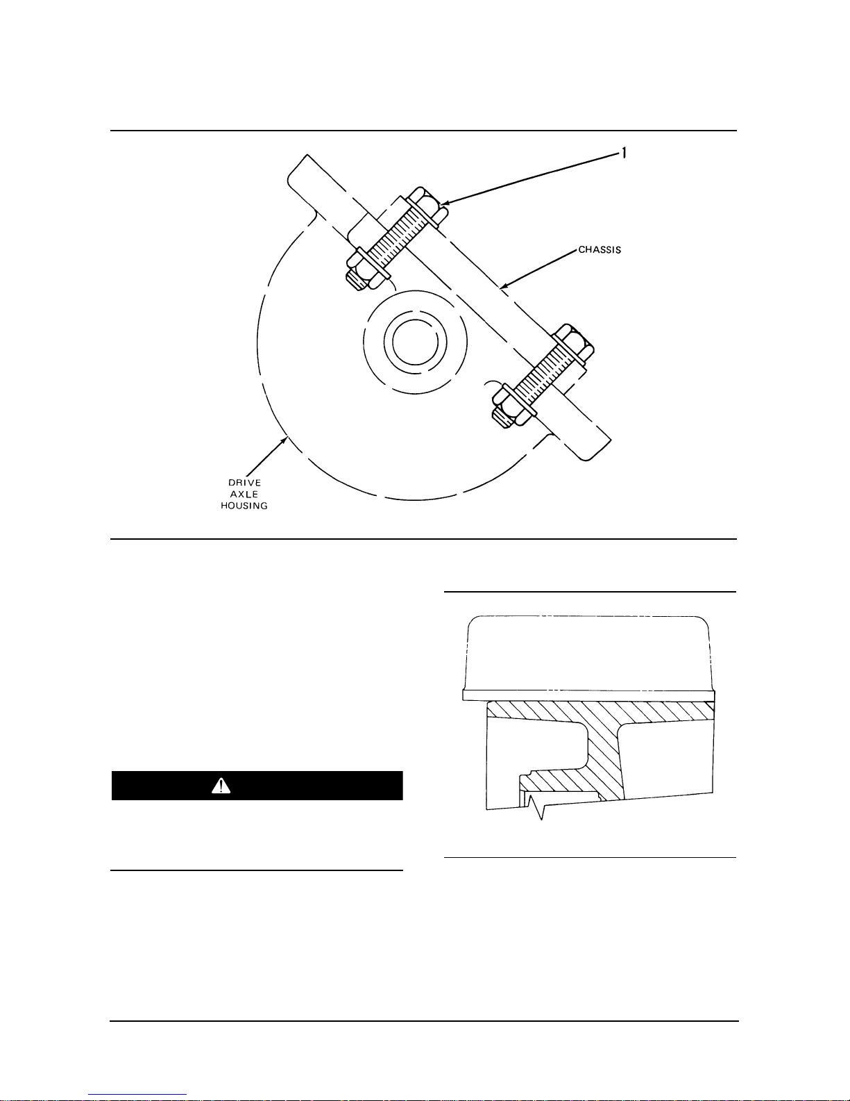
Drive Axle Mounting Group
(1) Install four bolts (1) that fasten drive axle housing
to the chassis frame. Tighten bolts (1) to a torque
of ...........................488 L 27 N¥m (360 L 20 lb¥ft)
Drive Tire Installation
B Series
The optional cushion drive tire must be installed
as shown. failure to do so will decrease machine
stability and cause possible personal injury.
Cushion Tire
Install the cushion tire so that the edge of the tire is
even with the outside edge of the wheel.
WARNING
Page 35

Power Train Specifications
Cushion Tire Mounting
Tighten the cushion tire wheel mounting bolts (1) to
a torque of ..................270 L 25 N¥m (200 L 18 lb¥ft)
Pneumatic Tire Mounting
Tighten the pneumatic tire wheel nuts (2) to a torque
of ................................644 L 34 N¥m (475 L 25 lb¥ft)
Use ÒcrisscrossÓ procedure to tighten the nuts.
BC Series
BC20S-2, BC25S-2
The drive tire must be installed as shown below.
Failure to do so will decrease the stability of the lift
truck and can cause injury to the operator.
Install the tire so that the edge of the tire is even with
the outside edge of the wheel.
WARNING
34
Page 36

Power Train Specifications
BC30S-2-Narrow Axle
BC30S Models-Narrow Axle
Install the tire so there is distance (X) between the
edge of the tire and the outside edge of the wheel.
Distance (X) is .............21.4 L 0.8 mm (.84 L .03 in.)
BC30S-2 wide Axle
BC30S Models-Wide Axle
Install the tire so there is distance (Y) between the
edge of the tire and the outside edge of the wheel.
Distance (Y) is......25.4 L 0.8 mm (1.00 L .03 in.)
35
Page 37

Power Train Disassembly & Assembly
Disassembly & Assembly
Brakes, Brake Adjuster And
Wheel Cylinder
Remove Brakes, Brake Adjuster
And Wheel Cylinder
1. Put the lift truck in position on tooling (A), and
remove the drive wheels. On B20/25/30S models,
remove the brake drum also.
2. Remove brake return springs (1), (2) and (3) with
a suitable brake shoe spring tool.
3. Remove brake retainer springs (4). Remove the
brake shoes.
4. Remove bolts (6) to remove wheel cylinder cover
(5).
5. Disconnect brake lines (7). Remove plungers (8)
from the wheel cylinder.
6. Remove bolts (9) to remove wheel cylinder (10).
Tools Needed A
Jack Stand 1
36
2
3
1
4
5
6
7
9
10
8
Page 38

Power Train Disassembly & Assembly
7. Remove bolt (11) to remove brake adjuster (12).
8. Disassemble the brake adjuster. Remove springs
(15) from the adjuster. Remove bolt (14), wheel
(16) and shims (13). Do the same for the other
side of the brake adjuster.
9. Disassemble the wheel cylinder. Remove dust
caps (20) from each end of the wheel cylinder.
10. Remove pistons (18) with seals (19) and spring
(17) from the wheel cylinder.
Install Brakes, Brake Adjuster And
Wheel Cylinder
1. Install spring (17) in the wheel cylinder.
NOTE: Put clean brake fluid on the seals and inside
of the wheel cylinder before assembly.
2. Install pistons (18) with seals (19) in the wheel
cylinder.
3. Install dust caps (20).
4. Install shims (13) on wheel (16). Install wheel (16)
in the brake adjuster with bolt (14). Do the same
for the other side of the brake adjuster. Install
springs (15) on the arms of the brake adjuster.
37
11
12
15
19
17
20
18
19
17
20
18
16
13
14
15
16
13
14
Page 39

Power Train Disassembly & Assembly
5. Install brake adjuster (12) and bolt (11) that holds
it. Tighten the bolt to a torque of 72 L 5 NIm (55 L
4 lbIft). See Brake Adjuster Installation in Testing
And Adjusting for further adjustments.
6. Install wheel cylinder (10) and bolts (9). Tighten
the bolts to a torque of 15 L 2 NIm (11 L 1 lbIft).
7. Install plungers (8). Connect brake lines (7), and
tighten the nuts to a torque of 14 L 2 NIm
(10 L 1 lbIft).
8. Install wheel cylinder cover (5) and bolts (6).
9. Install the brake shoes and brake retainer springs
(4).
10. Install brake return springs (1), (2) and (3) with a
suitable brake spring tool.
11. Install the brake drums on B20/25/30S
models. Install the drive wheels.
38
11
12
4
5
6
7
9
10
8
2
3
1
Page 40
Power Train Disassembly & Assembly
Power Transfer Group
Remove And Install Power Transfer
Group
Start By:
a. Remove transaxle
b. Remove final drives and hubs
1. The weight of power transfer group (1) is 50 kg
(110 lb). Install tool (A) on the power transfer
group, and attach a hoist.
2. Remove four bolts (2) and the power transfer
group. Remove the O-ring seal if it is necessary.
NOTE: The following steps are for installation of the
power transfer group.
3. Put the O-ring seal on the power transfer group if
it was removed. Put clean SAE 10W oil on the
seal.
4. Put the power transfer group in position on the
drive axle housing. Install the four bolts.
End By:
a. Install final drives and hubs.
b. Install transaxle.
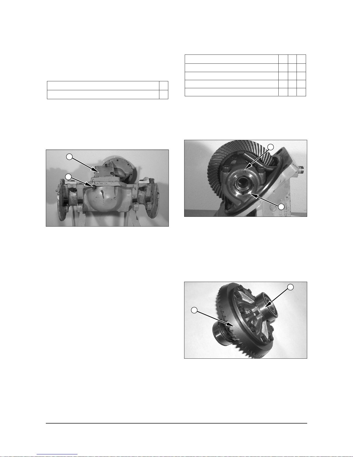
Disassemble Power Transfer Group
Start By:
a. Remove power transfer group.
1. Mark the bearing caps and locknuts for proper
installation. Bend the tab on the lockwasher back.
Remove locknuts (2) with tooling (A) and the
lockwashers. Remove bearing caps (1). The
weight of the carrier assembly with the bevel gear
is 50 kg (110 lb). Attach a hoist, and remove the
carrier assembly.
2. Remove two bearing cups (3). Remove the 10
bolts and bevel gear (4).
Tools Needed A B C
Spanner Wrench 1
Handle 1
Bearing Puller 1
Spanner Wrench 1
Tools Needed A
Link Bracket 1
39
2
1
1
2
3
4
Page 41

Power Train Disassembly & Assembly
3. Use a hammer and punch to remove roll pin (6)
from the carrier. Remove pin (8), side gears (7)
and the thrust washers.
4. Remove axle gears (9) and the thrust washers. If
bearing cones (5) need to be replaced, use tool
(B) and a press to remove them from the carrier.
5. Remove cover (10) from the housing assembly.
Remove the cap from over pinion nut (11). Bend
the lockwasher away from nut (11). Remove nut
(11) with tool (C). Remove the lockwasher and
washer.
6. Remove outer bearing cone (17), shims (23) and
ring (22) from the pinion shaft. Pull pinion shaft
(12) out of gear (15) and the housing assembly.
Remove ring (21) from the pinion shaft. Remove
the gear from the side of the housing assembly
that cover (10) was removed from.
7. If necessary, remove inner bearing cone (13) from
the pinion shaft with a press.
8. If necessary, remove bearing cups (18) and (20)
and shim (19) from the housing assembly.
9. Remove the snap ring (24) from the gear shaft
(26).
10. If necessary, remove the bearings (25) from the
gear shaft (26) with a bearing puller.
24
25
26
40
5
6
8
7
9
10
11
IDCD356S
12
13
21
15
22 17
11
20
23
19
18
Page 42

Power Train Disassembly & Assembly
Assemble Power Transfer Group
1. Install bearing cups (18) and (20) without shims
(19) behind cup (18) in the housing assembly.
Press bearing cone (13) on the pinion shaft.
2. Position pinion shaft (12) into the housing
assembly. Install outer bearing (17) and nut (11)
on the pinion shaft. Tighten the nut to a torque of
15 to 34 NIm (11 to 25 lbIft) while rotating the
pinion.
3. Put the bar and discs of tool (D) in the bearing
bores of the housing assembly as shown. Install
bearing caps (1), and tighten the bolts.
4. Measure the distance from the end of the pinion
shaft to the bottom of the bar with an inside
micrometer. Record this measurement.
5. Measure the outside diameter of the bar with an
outside micrometer. Divide this measurement by 2,
and add it to the recorded measurement of Step 4.
Record this total measurement.
24
20
26
23
25
19
18
12
11
17
10
15
2113
532
1
4
TOOLS NEEDED A C D E F
Spanner Wrench 1
Handle 1
Spanner Wrench 1
Pinion Depth Gauge 1
Shim Pack, 4.0 mm (.16Ó)
1
Dial Indicator Set 1
41
IDCD356S
12
13
21
15
22 17
11
20
23
19
18
IDCD359S
Page 43

Power Train Disassembly & Assembly
6. Calculate the required shim thickness as follows:
the nominal mounting distance L deviation from
nominal (as marked on the end of the pinion in
millimeters, either + or - number) = required
mounting distance. The measured distance (from
Step 5) - the required mounting distance =
required shim thickness. The measured distance
must be within 0.03 mm (.001 in) of the required
mounting distance. If it is, the correct thickness of
shims have been installed. If the required
mounting distance is greater than the measured
distance, remove some shims (19). If the required
mounting distance is less than the measured
distance, add some shims (19).
EXAMPLE 1:
78.00 mm (3.071 in) - nominal mounting distance
- 0.09 mm (.004 in) - deviation from nominal
(marked on end of pinion)
77.91 mm (3.067 in) - required mounting distance
78.10 mm (3.074 in) - actual mounting distance
from Step 5
- 77.91 mm (3.067 in) - required mounting distance
0.19 mm (.007 in) - thickness of shims
to be installed under cup (18)
EXAMPLE 2:
78.00 mm (3.071 in) - nominal mounting distance
- 0.09 mm (.004 in) - deviation from nominal
(marked on end of pinion)
77.91 mm (3.067 in) - required mounting distance
77.91 mm (3.067 in) - actual mounting distance
- 77.91 mm (3.067 in) - required mounting distance
0 mm (0 in) - thickness of shims that need
to be added or removed
from under cup (18)
7. If the original bearings and ring gear and pinion
set are used, install bearing cups (18) and (20)
with original amount of shims (19) behind bearing
cup (18) in the housing assembly. Press bearing
cone (13) on the pinion shaft.
8. Do Steps 2-5. To calculate if the installed shims
are the correct thickness, proceed as follows : the
nominal mounting distance L deviation from
nominal (as marked on the end of the pinion,
either + or - number) = required mounting
distance. The measured distance must be within
0.03 mm (.001 in.) of the required mounting
distance. If it is, the correct thickness of shims
have been installed. If the required mounting
distance is greater than the measured distance,
remove some shims (19). If the required mounting
distance is less than the measured distance, add
some shims (19).
9. After the pinion depth is correct, remove tool (D) and
pinion shaft (12) again.
10. Press bearings (25) on the gear shaft (26).
11. Install the gear shaft (26) in the housing. Install
the snap ring (24) on the gear shaft (26).
24
25
26
42
IDCD356S
12
13
21
15
22 17
11
20
23
19
18
15
21
13
12
Page 44

Power Train Disassembly & Assembly
12. Put ring (21) in position on the pinion shaft. Put gear
(15) in position in the housing assembly with the side
that has a recessed hub next to ring (21). Put the
pinion shaft in the housing assembly and through
gear (15).
13. Install ring (22). Install tooling (E). Install bearing
(17), the washer, lockwasher and nut (11).
Tighten the nut to a torque of 15 to 34 NIm (11 to
25 lbIft) while rotating the pinion.
14. Install tooling (F) as shown, and measure the
end play of pinion shaft (12). Record the
measurement. Remove nut (11), the lockwasher,
washer and bearing cone (17).
NOTE: Be sure to measure each shim in shim pack (E)
separately. The shims for setting rolling torque are not
shown in the parts book. The part numbers are:
15. Remove tooling (E). Measure the thickness of
tooling (E). Subtract from this thickness the
recorded end play from step (14). This is the
thickness of shims (23) that are needed with no
bearing preload (actual gauge thickness
measured end play = clearance).
16. In order to get bearing preload, subtract from the
shim pack found in Step 15, 0.05 mm (.002 in).
This is thickness of shims that need to be
installed.
17. Install the correct thickness of shims (23),
bearing cone (17), the washer, lockwasher and
nut (11). Tighten the nut to a torque of 180 L 25
NIm (135 L 18 lbIft) with tool (C) and lock within
this range.
PART NO. THICKNESS
924760 0.04 mm (.002 in)
924761 0.08 mm (.003 in)
924762 0.12 mm (.005 in)
924763 0.25 mm (.010 in)
924764 0.8 mm (.03 in)
924765 1.6 mm (.06 in)
43
IDCD361S
22
E
17
Page 45

Power Train Disassembly & Assembly
18. Check the rolling torque of the pinion as shown.
It must be 0.85 to 1.70 NIm (7.5 to 15.0 lbIin). If
the rolling torque is not correct, add or remove
shims (23) until it is correct. Removal of shims
(23) increases rolling torque. Adding shims (23)
decreases the rolling torque. Record the actual
rolling torque after the shims have been added or
removed. Do not put the cap over the pinion nut
yet.
19. If bearing cones (5) were removed, heat them to
135°C (275°F), and install them on the carrier.
Put the thrust washers and axle gears (9) in
position in the carrier.
20. Install the thrust washers, side gears (7) and pin
(8). Install roll pin (6) through the carrier and pin
(8).
21. Put bevel gear (4) on the carrier and the ten
bolts. Tighten the bolts to a torque of 70 L 15
NIm (50 L 11 lbIft). Put bearing cups (3) on the
bearing cones.
22. Put the carrier assembly in position in the
housing assembly. Install bearing caps (1) and
the four bolts. Tighten the bolts to a torque of 220
L 25 NIm (160 L 18 lbIft).
23. Install the lockwasher and locknuts (2). Install
tooling (F) as shown, and adjust locknuts (2) with
tooling (A) until there is a backlash of 0.13 to
0.20 mm (.005 to .008 in). To adjust backlash,
turn one locknut in and the other one out the
same amount of turns.
24. Check the rolling torque again as shown in step
18. Tighten locknuts (2) with tooling (A) equally to
preload the bearings. Proper bearing preload will
increase the recorded preload in Step 18 by 0.63
to 0.88 NIm (5.6 L 7.8 lbIin).
25. Measure backlash again. Bend a tab from each
lockwasher into a slot of locknuts (2) to hold
them in position.
44
5
6
8
7
9
3
1
2
4
Page 46
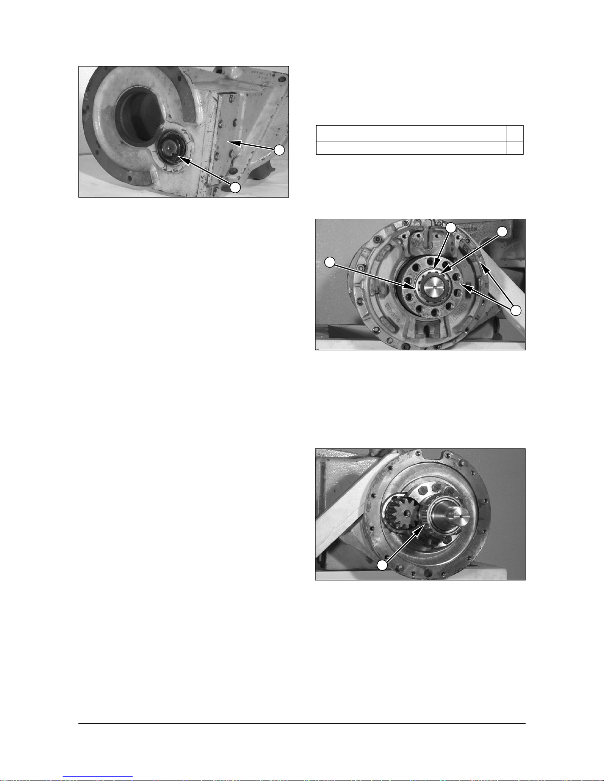
Power Train Disassembly & Assembly
26. After all the adjustments have been completed,
put Bearing Mount Compound on the outside
diameter of cap (11) and install it.
27. Put Gasket Maker on cover (10) and the housing
assembly. Also, use Quick Cure Primer if the
temperature is below 10 °C (50 °F).
End By:
a. Install power transfer group.
Final Drives And Hubs
Remove Final Drives And Hubs
Start By:
a. Remove brakes.
1. Bend back one of the tabs in locking washer (1).
2. Remove nut (3) with tool (A). Remove locking
washer (1) and bearing (2).
3. Remove cover and hub assembly (4).
4. Remove bearing cone (5) from the spindle.
Tools Needed A
Spanner Wrench 1
45
10
11
2
3
4
5
1
Page 47
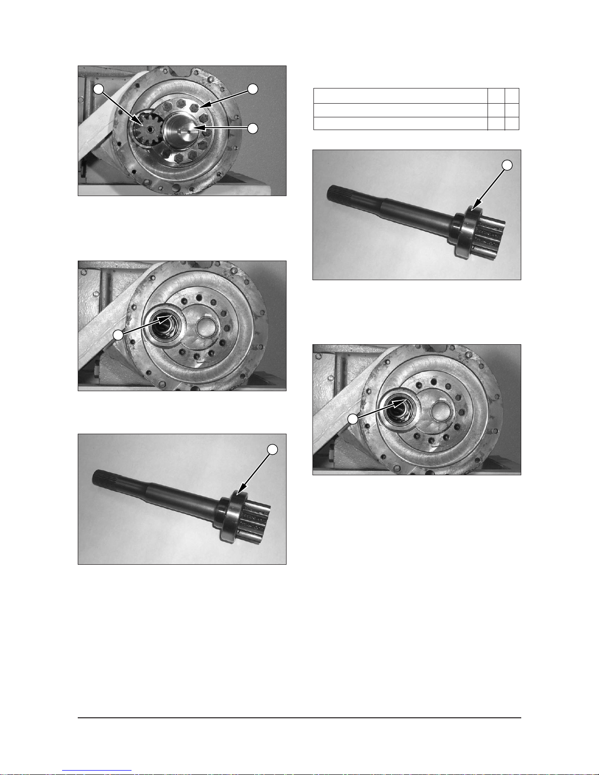
Power Train Disassembly & Assembly
5. Remove bolts (6), and remove spindle (7).
6. Remove shaft assembly (8).
7. Remove lip seal (9) from the housing.
8. Remove the retainer and bearing (10) from the
shaft.
Install Final Drives And Hubs
1. Install bearing (10) with a press. Heat the retainer
to 317 to 427°C (700 to 801°F) and install it
against bearing (10) with a press.
2. Install lip seal (9) in the housing with tool group
(B) and a suitable press. Install the seal with the
lip toward the inside.
Tools Needed A B
Spanner Wrench 1
Driver set 1
46
6
8
7
9
9
10
10
Page 48

Power Train Disassembly & Assembly
3. Install shaft assembly (8) in the housing.
4. Put Loctite No.242 Thread Sealant on th threads
of the bolts that hold the spindle.
5. Put spindle (7) in position, and install bolts (6) that
hold it. Tighten the bolts to a torque of 115 L 14
NIm (85 L 10 lbIft).
6. Install bearing (5) on the spindle.
7. Put hub and cover assembly (4) in position on the
housing, and install the bolts that hold it. Tighten
the bolts to a torque of 55 L10 NIm (41 L 7 lbIft).
8. Install bearing (2) locking washer (1) and nut (3)
on the spindle.
9. With tool (A), tighten nut (3) slowly to 135 NIm
(100 lbIft) while the hub is turned to put the
bearings in position.
10. Loosen nut (3) completely, and tighten it again to
a torque of 50 L 5 NIm (37 L 4 lbIft).
11. Bend one of the tabs in washer (1) to hold the nut
in position.
End By:
a. Install brakes.
47
2
3
4
1
6
8
7
5
Page 49

Power Train Disassembly & Assembly
Oil Cooled Disc Type Brake
Remove & Install Brakes
(Oil Cooled Disc Type)
NOTE : The procedure to remove and install oil
cooled disc type brakes is the same for both sides of
the machine.
1. Put the lift truck in position on tooling (A).
2. Remove the bolts (1) and wheel (2).
3. Remove bolts (3) and adapter (4).
4. Remove bolts (5) and cover (6).
5. remove the plates and discs (7) from hub (8).
6. Remove piston (9) from hub (8).
7. Remove bolts (10) and hub (8).
NOTE : Check the condition of all O-ring seals and
components. If any seals or components are worn or
damaged use new parts for replacement.
Tools Needed A
Jack Stand 4
48
IDCD382S
3
4
5
7
8
6
8
9
10
Page 50

Power Train Disassembly & Assembly
NOTE : Use the following steps to install the oil cooled
disc type brakes. If new discs (7) are installed, soak
the discs in transmission drive train oil for one hour
prior to installation. Refer to the Operation and
Maintenance Manual for further information.
8. Put Loctite No. 17430 on the mating surfaces of
hub (8) and the transaxle housing. Install hub (8)
and bolts (10).
9. Install piston (9).
10. Install the plates and discs (7) into hub (8).
11. Put Loctite No.17430 on the mating surfaces of
hub (8) and cover (6). Install bolts (5) and cover
(6).
12. Install adapter (4) and bolts (3).
13. Install bolts (1) and wheel (2).
14. Bleed the brake system. Refer to the Testing and
Adjusting Manual for further information.
15. Remove tooling (A).
6
7
8
9
49
3
4
8
5
6
 Loading...