

Daewoo AMI-325MU, AMI-225MU Service Manual

Service Manual
MINI COMPONENT SYSTEM
Model :
DAEWOO ELECTRONICS CO., LTD.
AMI-225M/MU
AMI-325M/MU

Table of Contents
Model No:AMI-225M/MU, 325M/MU
- 1 -
SAFETY PRECAUTIONS......................................................................................... 2
ADJUSTMENTS....................................................................................................... 4
EXPLODED VIEW AND PARTS LIST ...................................................................... 6
WIRING DIAGRAM ................................................................................................... 8
BLOCK DIAGRAM .................................................................................................... 9
SCHEMATIC DIAGRAM ........................................................................................... 10
POWER / AMP ................................................................................................................................ 10
CD ......................................................................................................................................................12
TUNER ...............................................................................................................................................13
TAPE .................................................................................................................................................14
CONTROL .........................................................................................................................................15
PCB PATTERN LAYOUT ........................................................................................ 16
ELECTRICAL PART LIST ....................................................................................... 19
Safety Precautions
- 2 -
WARNING
: TO PREVENT FIRE OR ELECTRIC SHOCK, DO NOT EXPOSE
THIS APPLIANCE TO RAIN OR MOISTURE.
CAUTION :
TO REDUCE THE RISK IF ELECTRIC SHOCK, DO NOT
REMOVE COVER (OR BACK). NO USER SERVICEABLE PARTS
INSIDE.
REFER SERVICING TO QUALIFIED SERVICE PERSONNEL.
THIS SYMBOL IS INTENDED TO ALERT THE USER TO THE
PRESENCE OF UNINSULTED "DANGEROUS VOLTAGE"
WITHIN THE PRODUCT'S ENCLOSURE THAT MAY BE
SUFFICIENT MAGNITUDE TO CONSTITUTE A RISK OF
ELECTRIC SHOCK TO PERSONS.
THIS SYMBOL IS INTENDED TO ALERT THE USER TO THE
PRESENCE OF IMPORTANT OPERATING AND MAINTENANCE
(SERVICING) INSTRUCTIONS IN THE LITERATURE
ACCOMPANYING THE APPLIANCE.
CAUTION
TO PREVENT ELECTRIC SHOCK, DO NOT USE THIS POLARIZED AC
PLUG WITH AN EXTENSION CORD, RECEPTACLE OR OTHER OUTLET
UNLESS THE BLADES CAN BE FULLY INSERTED TO PREVENT BLADE
EXPOSURE.
LASER SAFETY
THIS UNIT EMPLOYS A LASER. ONLY QUALIFIED SERVICE PERSONNEL
SHOULD REMOVE THE COVER OR ATTEMPT TO SERVICE THIS DEVICE
DUE TO POSSIBLE EYE INJURY.
CAUTION :
USE OF ANY CONTROLS, ADJUSTMENTS, OR PROCEDURES
OTHER THAN THOSE SPECIFIED HEREIN MAY RESULT IN HAZARDOUS
RADIATION EXPOSURE.
CAUTION :
TO PREVENT ELECTRIC SHOCK, MATCH WIDE BLADE OF
PLUG TO WIDE SLOT, FULLY INSERT.
ATTENTION :
POUR EVITER LES CHOCS ELECTRIQUES, INTRODUIRE
LA LAME LA PLUS LARGE DE LA FICHE DANS LA BORNE CORRESPONDANTE DE LA PRISE ET POUSSER JUSQU'AU FOND.
Important Safety Instructions
- All the safety and operating instructions should be read before
the appliance is operated.
- The safety and operating instructions should be retained for
future reference.
- All warnings on the appliance and in the operating instructions
should be adhered to.
- All operating and use instructions should be followed.
1. Water and Moisture - The appliance should not be
used near
water - for example, near a bathtub, washbowl, kitchen sink,
laundry tub, in a wet basement, or near a swimming pool,
and the like.
2. Carts and Stands - The appliance
should be used only with a cart or
stand that is recommended by th
manufacturer.
3. An appliance and cart combination
should be moved with care. Quick
stops, excessive force, and uneven
surfaces may cause the appliance
and cart combination to overturn.
4. Wall or Ceiling Mounting - The appli-
ance should be mounted to a wall or
ceiling only as recommended by the manufacturer.
5. Ventilation - The appliance should be situated so
that its
location or position does not interfere with
its proper
ventilation. For example, the appliance
should not be situated
on a bed, sofa, rug, or similar surface that may block the
ventilation openings; or, placed in a built-in installation, such
as a bookcase or cabinet that may impede the flow
of air
through the ventilation openings.
6. Heat - The appliance should be situated away from
heat
sources such as radiators, heat registers,
stoves, or other
appliances (including amplifiers) that produce heat.
7. Power Sources - The appliance should be
connected to a
power supply only of the type described in the operating
instructions or as marked on the appliance.
8. Grounding or Polarization - The precautions that
should be
taken so that the grounding or polarization means of an
appliance is not defeated.
9. Power - Cord Protection - Power-supply cords
should be
routed so that they are not likely to be
walked on or pinched
by items placed upon or against them, paying particular
attention to cords at plugs, convenience receptacles, and the
point where they exit from the appliance.
10.Protective Attachment Plug - The appliance is equipped with
an attachment plug having overload protection. This is a
safety feature. See Instruction Manual for replacement or
resetting of protective device. If replacement of the plug is
required, be sure the service technician has used a
replacement plug specified by the manufacturer that has the
same overload protection as the original plug.
11.Cleaning - The appliance should be cleaned only as
recommended by the manufacturer.
12.Power Lines - An outdoor antenna should be located
away
from power lines.
CAUTION
RISK OF ELECTRIC SHOCKS
DO NOT OPEN
PORTABLE CART
Figure 2
Safety Precautions
- 3 -
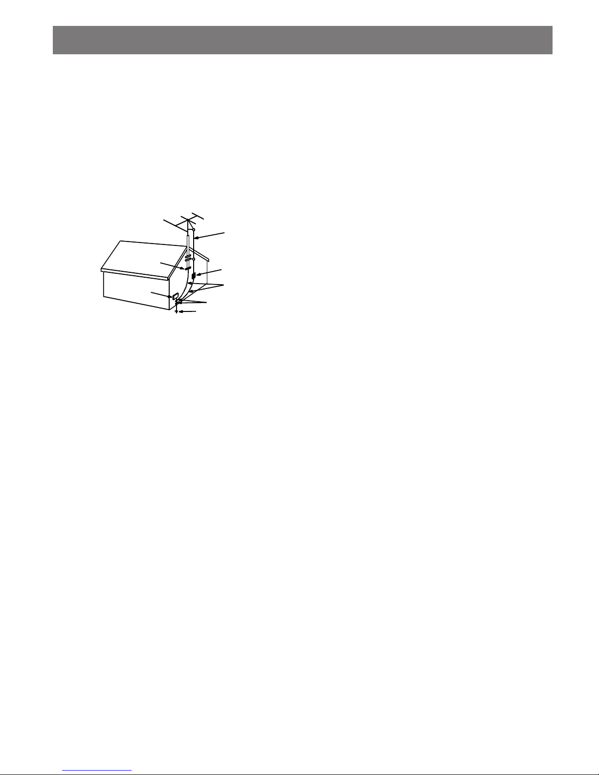
13.Outdoor Antenna Grounding - If an outside antenna
is
connected to the receiver be sure the antenna
system is
grounded so as to provide some protection against voltage
surges and built-up static charges. Article 810 of the National
Electrical Code, ANSI/NFPA 70, provides information with
regard to proper grounding of the mast and supporting
structure, grounding of the lead-in wire to an antenna-dis
charge unit, size of grounding conductors,location of antennadischarge unit, connection to grounding electrodes and
requirements for the grounding electrode. See Figure 1.
14.Non-use Periods - The power cord of the appliance should be
unplugged from the outlet when left unused for a long period
of time.
15.Object and Liquid Entry - Care should be taken so
that objects
do not fall and liquids are not spilled into the enclosure through
openings.
16.Damage Requiring Service - The appliance should
be
serviced by qualified service personnel when:
a) The power-supply cord or the plug has been
damaged; or
b) Objects have fallen, or liquid has been spilled
into the
appliance; or
c) The appliance has been exposed to rain; or
d) The appliance does not appear to operate
normally or
exhibits a marked change in performance; or
e) The appliance has been dropped, or the
enclosure
damaged.
17.Servicing - The user should not attempt to service the
appliance beyond that described in the operating instructions.
All other servicing should be referred to qualified service
personnel.
ANTENNA DISCHARGE UNIT
(NEC SECTION 810-20)
ANTENNA LEAD
IN WIRE
POWER SERVICE GROUNDING
ELECTRODE SYSTEM
(NEC ART 250 PART H)
GROUND CLAMP
ELECTRIC
SERVICE
EQUIPMENT
GROUNDING CONDUCTORS
(NEC SECTION 810-21)
GROUND CLAMPS
EXAMPLE OF ANTENNA
GROUNDING
NEC - NATIONAL ELECTRICAL CODE
Adjustments
- 4 -
SET
FM Antenna
Terminal(75 ohm)
Carrier Frequency : 98MHz
Output Level : 26dBuV
Modulation:Audio 1kHZ, 75kHz Deviation
FM RF SSG
75 ohm Coaxal
Level : 1.2+0.3Vp-p
RF Signal Waveform
VOLT/DIV : 200mV
TIME/DIV : 50ns
Traverse Waveform
A
B
0V
Check Point
Confirm
: No Adjustment : OPTION
Confirm stereo
indicator is
lighted and L/R
channel is
seperated.
Confirm FM
wave
VTVM
Scope
R-CH
L-CH
47 kohm
47 kohm
Input Level
Measurement
Point
Input Point
Output Level
Measurement
Point
Test Tape : MTT-111N(3kHz)
MTT-5511(Blank)
Frequency Counter
Output Level
Measurement Point
Set
Forward
Side
Reverse
Side
Adjust with Frequency
Counter Connected
L-CH
Peak
R-CH
Peak
Screw
Angle
Output Level
within
1 dB
within
1 dB
L-CH
Peak
R-CH
Peak
Screw Angle
V H
Oscilloscope
L-CH
Output Level
Measurement Point
Set
Test Tape
MTT-114N
(10kHz)
Screen Pattern
In Phase 45 90 135 180
Good Wrong
RV701
RV701
L601
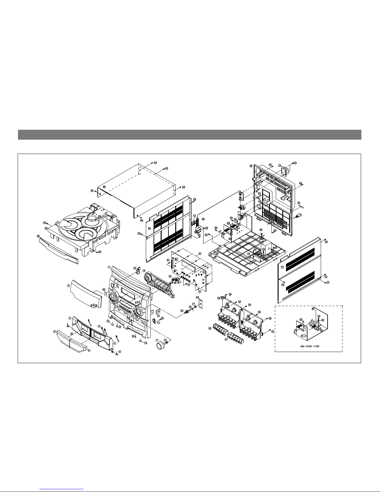
Exploded View and Mechanical Parts List
- 6 -
Model No:AMI-225M/MU, 325M/MU
- 7 -
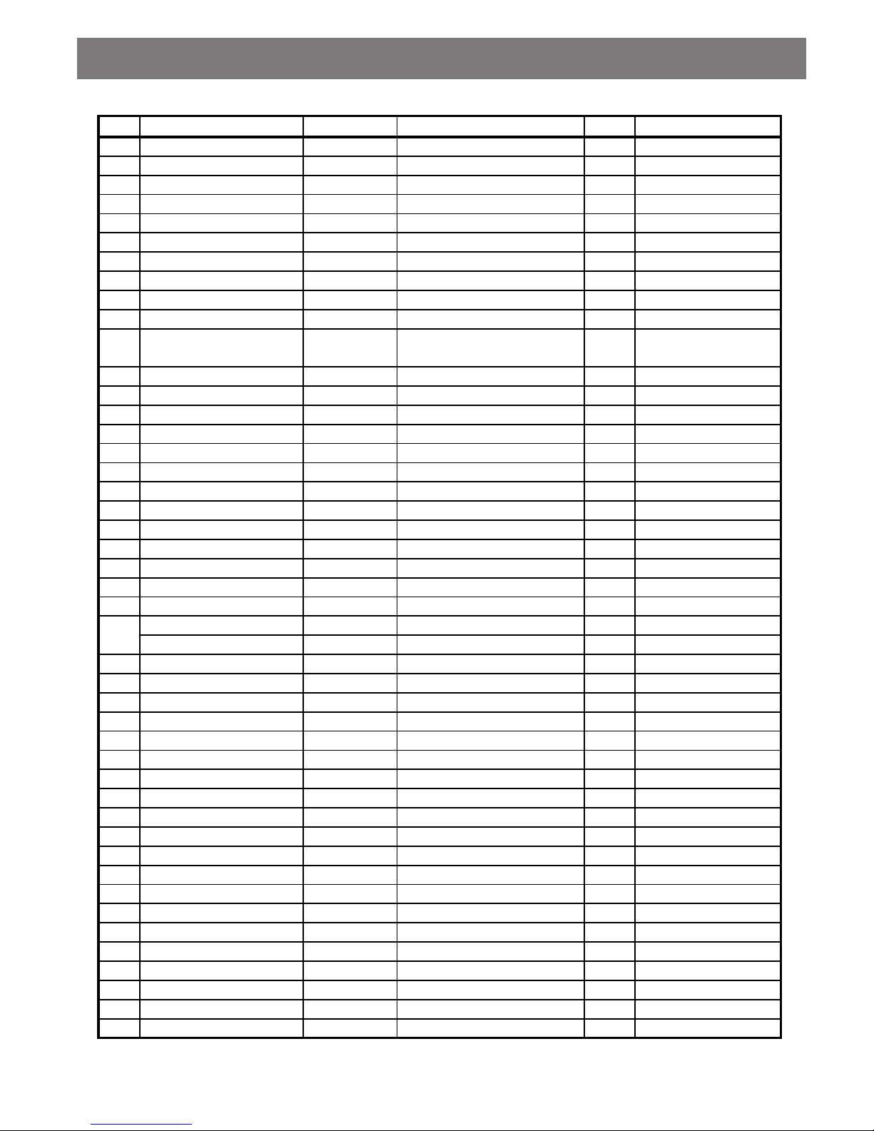
Mechanical Part List
NO Part Name Parts Code Q'ty Comment
1 PANEL FRONT 9CD0307900 1
2 WINDOW FLT 9CD1616400 1
3 DOOR CASS A 9CD18111A0 1
4 DOOR CASS B 9CD18111B0 1
5 WINDOW DOOR A 9CD16163A0 1
6 WINDOW DOOR B 9CD16163B0 1
7 KNOB VOLUME 9CD1339800 1
8 SPRING DOOR EJECT 9CD3004500 2
9 SPRING C HOLDER 9713008900 4
10 CUSHION FOOT 9CD4207700 2
11 DAMPER ASSY
9CD2603000
9CD2603100
1
12 BRAKET SIDE 9CD2412900 2
13 KNOB CONTROL 9CD1339500 1
14 KNOB CD 9CD1339700 1
15 KNOB POWER 9CD1339600 1
16 SHAFT VR 9CD3601900 1
17 SHAFT WASHER 9CD3602000 2
18 SPRING TUNING 9CD3007000 1
19
CASS DECK MECHANISM
9CD6007900 1
OPTION
20 KNOB DECK A 9CD13329R1 1
21 KNOB DECK B 9CD13330R1 1
22 DOOR CD 9CD1811200 1
23 CD DECK MECHSNISM 9CD6006900 1
24 HEAT SINK 05 9CD4405100 1
24-1 HEAT SINK 1 9CD4404500 1 OPTION
25 CHASSIS BOTTOM 9CD0608000 1
26 COVER SIDE L 9CD04115L0 1
27 COVER SIDE R 9CD04115R0 1
28 COVER BACK 9CD0409801 1
29 COVER TOP 9CD0411400 1
30 PLATE EON 9CD0910100 1
31 COVER ANT 9CD0410400 1
OPTION
32 LABEL SPK (6¥Ø) 9CD9309400 1
S1 SCREW TAPPTITE 7173260811 11
S2 SCREW TAPPTITE 7173301011 17
S3 SCREW TAPPTITE 7173301212 18
S4 SCREW TAPPTITE 7173401011 4
S5 SCREW TAPPTITE 7173300811 5
S6 WASHER SCREW 9CD3102400 1
P1 PCB FRONT 9CD6579800 1
P2 PCB MAIN 9CD6580000 1
P3 PCB FUSE 9CD6579700 1
P4 PCB GUIDE 9CD6579801 1
ABS
MIPS
ABS
ABS
ABS
ACETAL
SUS D0.6 ACD-7600
AUTO STOP
ABS
ABS
Description
MIPS
ACRYL
MIPS
MIPS
ACRYL
ACETAL
ACRYL
PW-1
ABS
STS (T=0.2)
URETHAN FOAM RUBBER
DA-12A
MIPS
DCC-01B
AL (5W)
MIPS
AL (10W)
MIPS
MIPS
MIPS
PVC SHEET
ABS
PE FILM
TT2 BIN 3X12 BK
TT2 BIN 4X10 MFZN
TT2 BIN 2.6X8 MFZN
TT2 BIN 3X10 MFZN
34 x 75 x 1.6T
13 x 32 x 1.6T
330 x 197 x 1.6T
247 x 139 x 1.6T
TT2 BIN 3X8 MFZN
TT2 BIN 3X10+D14
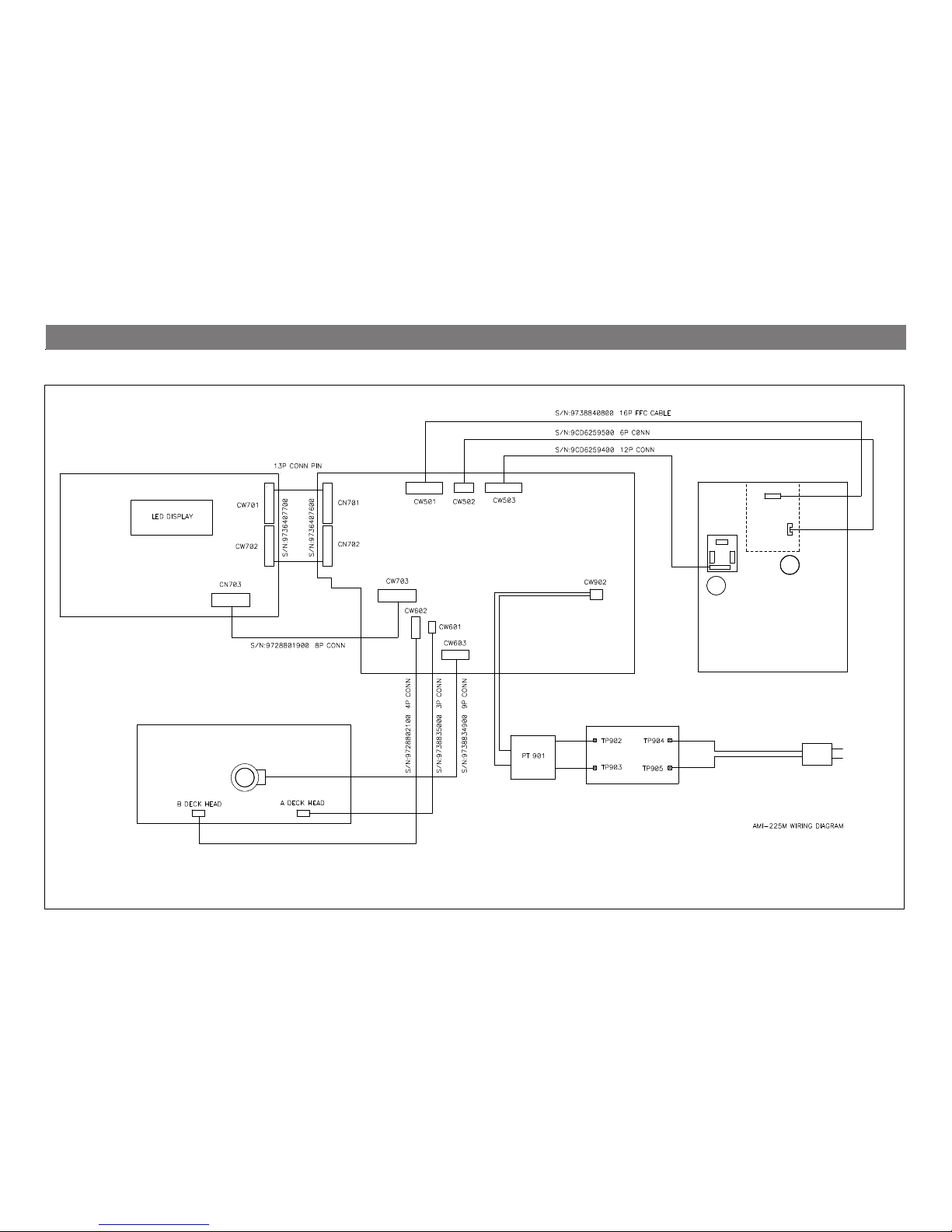
- 8 -
AMI-225M/MU, 325M/MU
A3A3
CASETTE DECK
M
M
FRONT PCB ASSY
S/N :
MAIN PCB ASSY
S/N :
POWER TRANS
Pick-Up
FUSE PCB ASSY
S/N :
MM
CD MECHA. ASS'Y
MM
AC CORD
WIRING DIAGRAM
 Loading...