


Daewoo AKR-0108 Series, AKR-0106 Series, AKR-1010 Series, AKR-0106A, AKR-1010RC Service Manual
...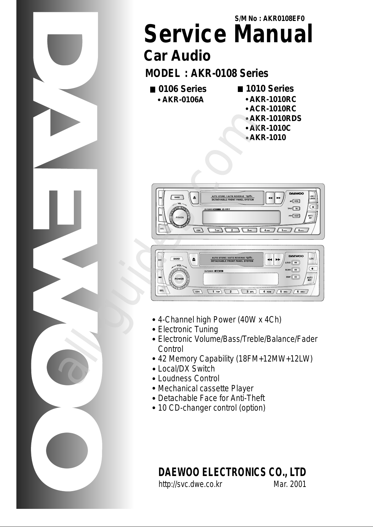
1010 Series
AKR-1010RC
ACR-1010RC
AKR-1010RDS
AKR-1010C
AKR-1010
Service Manual
Car Audio
S/M No : AKR0108EF0
DAEWOO ELECTRONICS CO., LTD
http://svc.dwe.co.kr Mar. 2001
4-Channel high Power (40W x 4Ch)
Electronic Tuning
Electronic Volume/Bass/Treble/Balance/Fader
Control
42 Memory Capability (18FM+12MW+12LW)
Local/DX Switch
Loudness Control
Mechanical cassette Player
Detachable Face for Anti-Theft
10 CD-changer control (option)
MODEL : AKR-0108 Series
0106 Series
AKR-0106A
All manuals and user guides at all-guides.com
all-guides.com

TABLE OF CONTENTS
1. PRODUCT SPECIFICATIONS ..................................................1
2. LINE DRAWING ........................................................................2
3. EMERGENCY TROUBLE SHOOT ............................................3
4. ADJUSTMENTS ........................................................................6
5. SCHEMATIC DIAGRAM ..........................................................10
6. PARTS LOCATION ON P.C.BOARD ......................................11
7. OVERALL EXPLODED VIEW & PARTS LIST .......................14
8. DECK MECHANISM EXPLODED VIEW & PARTS LIST .......15
9. PARTS LIST ............................................................................18
10. FUNCTION OF MICOM IC .....................................................22
11. IC BLOCK DIAGRAM .............................................................28
12. WIRING DIAGRAM ...............................................................32
13. LIQUID CRYSTAL DISPLAY ..................................................33
14. OUTPUT CONNECTION DESCRIPTIONS ............................34
All manuals and user guides at all-guides.com

1
1. PRODUCT SPECIFICATIONS
AUDIO SECTION
Maximum output power : 40watts per channel into 4 ohms.
Load impedance : 4 ohms or 8 ohms
Total harmonic distortion : Less than 10% at 12 watts
Frequency response : 100Hz( +3dB), 10kHz(-5 +3dB)
Control Bass/Treble : 10 +3dB at 100Hz/10kHz
TAPE SECTION
Track format : 2-track / 2-channel system
Tape speed : 4.75cm/sec
Wow / Flutter : 0.35%max. (WRMS)
Frequency response : 63Hz ~ 10kHz (+3dB) normal (LH)tape
Signal to noise ratio : 50dB
Channel separation : 35dB
TUNER SECTION
(FM) Tuning range : 87.5 to 108MHz
Sensitivity : 12dBuV
Stereo separation : 30dB
Signal to noise ratio
:
55dB
Frequency range : 87.5 ~ 108MHzII
Channel space : 50KHz at Europe
(MW) Tuning range : 522 to 1620kHz at Europe
(530 to 1710KHz at U.S.A)
Sensitivity : 30dBuV
Signal to noise ratio
:
50dB
Frequency range : 522 ~ 1620KHz
Channel space : 9KHz
(LW) Tuning range : 144 to 288KHz
Usable Sensitivity : 40dBuV
GENERAL
Power requirements : DC 13.8V (10.8 ~15.6V allowable)
Negative ground
Spdaker impedance : 4 or 8 ohm
Output power : Maximum 40Wx4Ch.
Current consumption : 10A
Dimension (W x H x D) : 178 x 50 x 156 mm
Chassis size : 195 x 64 x 14.6 mm
Weight(Net) : 1.75Kg
Design and specifications are subject to changes for improvements without notice.
All manuals and user guides at all-guides.com

2
2. LINE DRAWING
2-1. FRONT SIDE
2-2. REAR SIDE
AKR-1010RC
- RDS Function
- 4-Channel high Power (40W x 4Ch)
- Electronic Tuning
- Electronic Volume /Bass /Treble
/Balance /Fader Control
- 42 Memory Capability
(18FM+12MW+12LW)
- Local/DX Switch
- Loudness Control
- Mechanical cassette Player
- Detachable Face for Anti-Theft
- 10 CD-changer control
AKR-1010C AKR-0106A
- Basic Function
- 4-Channel high Power (40W x 4Ch)
- Electronic Tuning
- Electronic Volume /Bass /Treble
/Balance /Fader Control
- 42 Memory Capability
(18FM+12MW+12LW)
- Local/DX Switch
- Loudness Control
- Mechanical cassette Player
- Detachable Face for Anti-Theft
- 10 CD-changer control
All manuals and user guides at all-guides.com

3
3. EMERGENCY TROUBLE SHOOT
3-1. General Function
No sound from
speakers
Yes
No
Yes
Output connector
is missing
Output connector
is inferior goods
Put exactly output
connector in.
Change output
connector to
superior goods
Yes
No
Power IC, Output
Socket is inferior
goods
Change Power IC,
Output Socket to
superior goods
Yes
A
A
L.C.D or Lamp
is not turned
off.
Yes
No
Yes
Power is not
supplied
Return to
Output voltage of
power IC is little.
Change Regulator
IC and check
output voltage.
Yes
No
LCD or Lamp is
inferior goods.
Change LCD or
Lamp to superior
goods.
Yes
Different each
channel have
output level
(Front, Rear,
Left, Right)
Treble or Bass
is low
unusually
Yes
No
Yes
Balance of front
and rear is in one
side
Balance of Left,
Right is in one
side.
Re-adjust Balance
of front, rear
Ref.
Balance = Center
Front / Rear
Ref.
Balance = Center
Left / Right
Ref.
Balance = Center
Treble / Bass
Ref.
Regulator IC output
Voltage = V
Ref.
Electrical Parts List
L.C.D., Lamp
Re-adjust Balance
of Left, Right
Yes
Yes
Balance of Treble
or Bass is in one
side.
Re-adjust Balance
of Treble or Bass
Yes
All manuals and user guides at all-guides.com

4
EMERGENCY TROUBLE SHOOT
3-2. Tuner Function
Hearing noise
only
Yes
No
Yes
No selected the
station
Tuner Module is
inferior goods.
Select exactly
broadcasting
frequency.
Change tuner
module to
superior goods.
Yes
Weak frequency
area caused by
elevations
Change to goods of
R.D.S function.
Yes
A
B
A
Station in
other regions
are not held.
Yes Yes
No selected the
local stations.
Return to or
Extreme noise
in broadcast
Weak
separation of
FM stereo
Yes
No
Yes
Antenna
connector is
missing
Put exactly
antenna connector
in his jack
Ref.
CAT-7
Electrical Parts List
Function of auto-
switch noise
reduction
Ref.
Yes
Weak frequency
area of FM, MW
Switch
automatically to
mono mode in
weak frequency
area
Yes
B
R1
In case of located Glass Antenna, check if heat wire is cut or not in rear window.
R2
Check Antenna connector part.
All manuals and user guides at all-guides.com
all-guides.com
5
EMERGENCY TROUBLE SHOOT
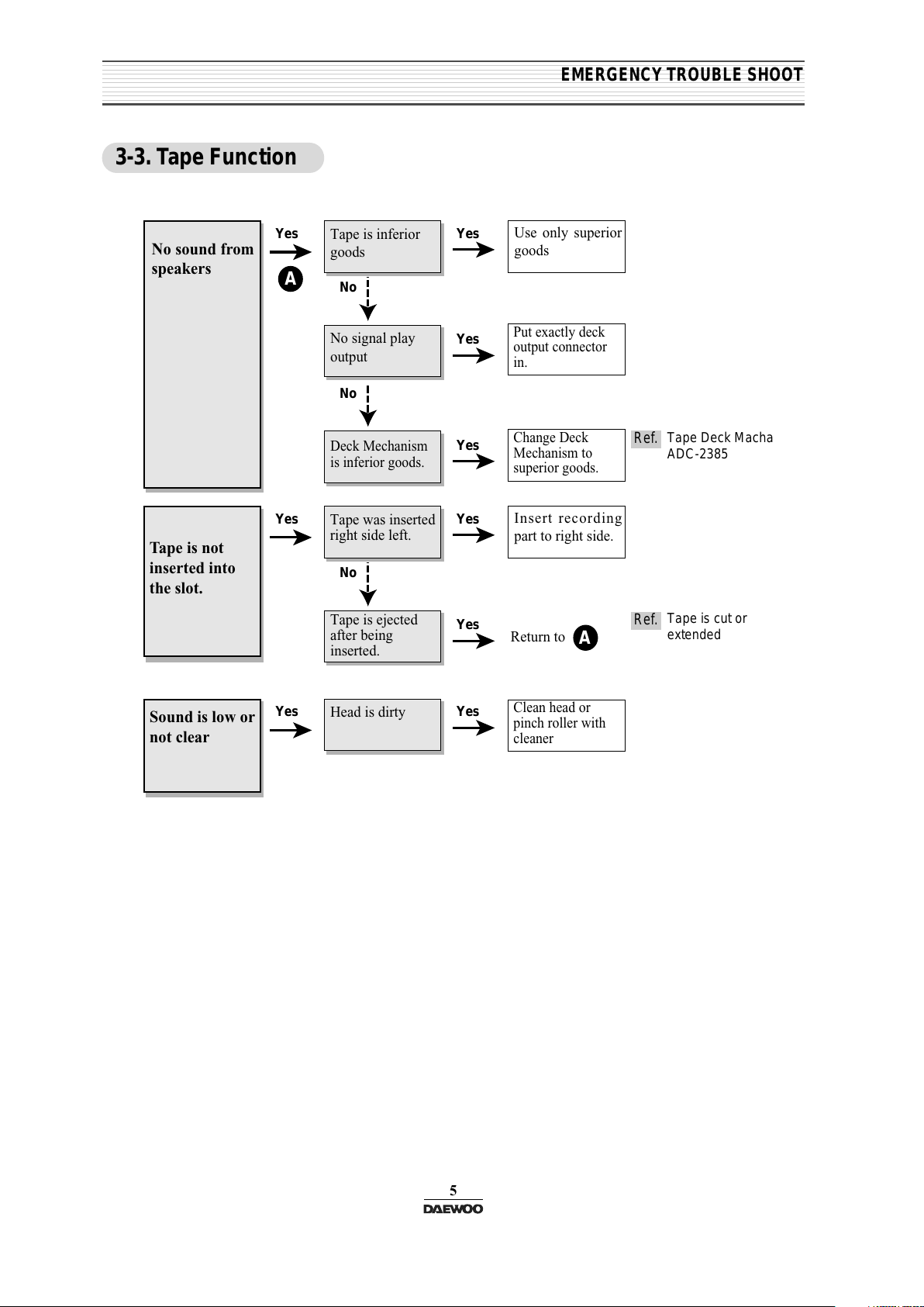
3-3. Tape Function
No sound from
speakers
Yes
No
Yes
Tape is inferior
goods
No signal play
output
Use only superior
goods
Put exactly deck
output connector
in.
Yes
No
Deck Mechanism
is inferior goods.
Change Deck
Mechanism to
superior goods.
Yes
A
A
Sound is low or
not clear
Yes Yes
Head is dirty
Return to
Clean head or
pinch roller with
cleaner
Tape is not
inserted into
the slot.
Yes
No
Yes
Tape was inserted
right side left.
Tape is ejected
after being
inserted.
Insert recording
part to right side.
Ref.
Tape Deck Macha
ADC-2385
Ref.
Tape is cut or
extended
Yes
All manuals and user guides at all-guides.com
4.
ADJUSTMENTS
6
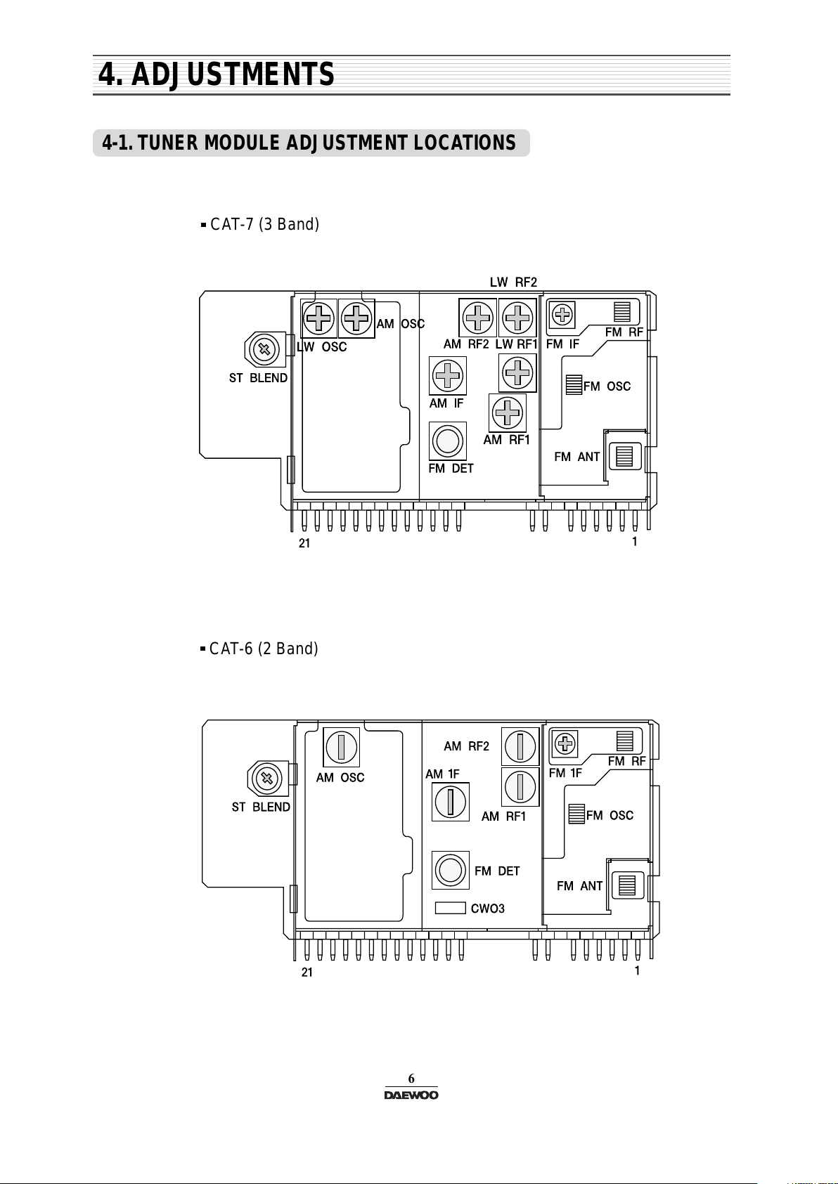
4-1. TUNER MODULE ADJUSTMENT LOCATIONS
CAT-7 (3 Band)
CAT-6 (2 Band)
All manuals and user guides at all-guides.com

ADJUSTMENTS
4-2. MW / LW ADJUSTMENT METHOD
7
STEP
MW
LW
Band Covering
Range
IF
522 KHz
522 KHz
603 KHz
V.T point of
AM Board
Output
Output
522 KHz
450 KHz
603 KHz
AMOSC
MAXIMUM
1620 KHz
1620 KHz -
7.6V
MAXIMUM
MAXIMUM
AMIF
AMRF1
AMRF2
1404 KHz
Output
1404 KHz
MAXIMUM
AMRF1
AMRF2
TRACKING
ALIGNMENT
TUNING
TEST
POSITION
SSG
FREQUENCY
ALIGNMENT
INDICATOR
Band Covering
Range
144 KHz
144 KHz
LWOSC
MAXIMUM
TRACKING
220 KHz
Output
220 KHz
LMRF1
LMRF2
MAXIMUM
All manuals and user guides at all-guides.com
ADJUSTMENTS
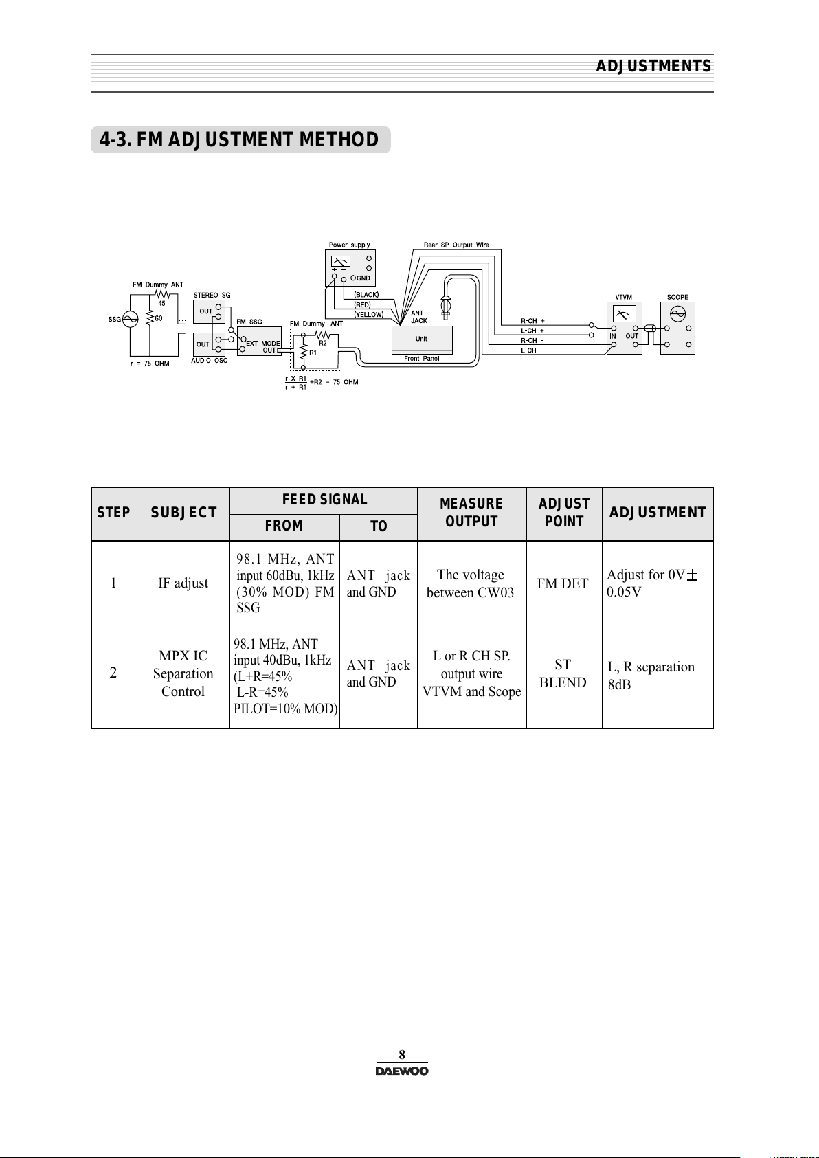
4-3. FM ADJUSTMENT METHOD
8
STEP
1 IF adjust
MPX IC
Separation
Control
98.1 MHz, ANT
input 60dBu, 1kHz
(30% MOD) FM
SSG
ANT jack
and GND
ANT jack
and GND
98.1 MHz, ANT
input 40dBu, 1kHz
(L+R=45%
L-R=45%
PILOT=10% MOD)
The voltage
between CW03
L or R CH SP.
output wire
VTVM and Scope
FM DET
ST
BLEND
Adjust for 0V
0.05V
L, R separation
8dB
2
SUBJECT
FEED SIGNAL
FROM
TO
MEASURE
OUTPUT
ADJUST
POINT
ADJUSTMENT
All manuals and user guides at all-guides.com
ADJUSTMENTS
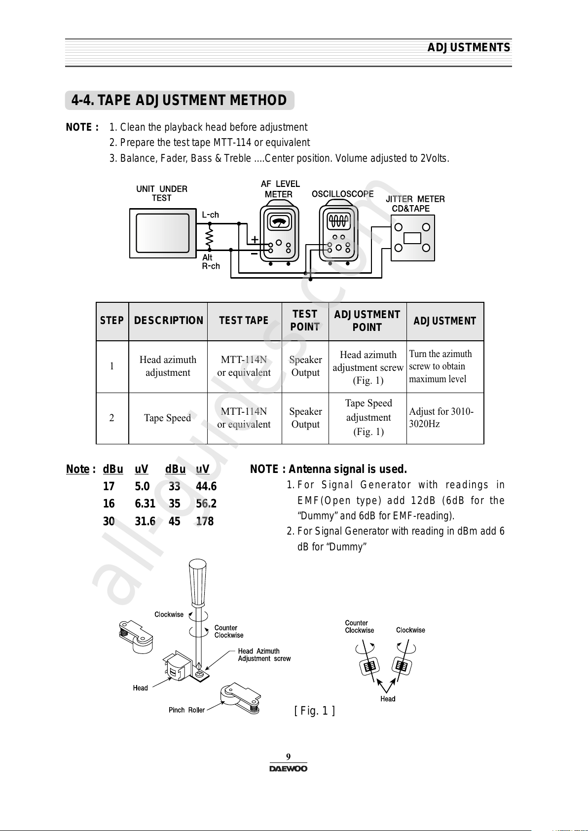
4-4. TAPE ADJUSTMENT METHOD
9
NOTE : 1. Clean the playback head before adjustment
2. Prepare the test tape MTT-114 or equivalent
3. Balance, Fader, Bass & Treble ....Center position. Volume adjusted to 2Volts.
STEP
1
Head azimuth
adjustment
Tape Speed
MTT-114N
or equivalent
MTT-114N
or equivalent
Speaker
Output
Speaker
Output
Head azimuth
adjustment screw
(Fig. 1)
Turn the azimuth
screw to obtain
maximum level
Adjust for 3010-
3020Hz
Tape Speed
adjustment
(Fig. 1)
2
DESCRIPTION
TEST TAPE
TEST
POINT
ADJUSTMENT
POINT
ADJUSTMENT
Note
: dBu uV dBu
uV
17 5.0 33 44.6
16 6.31 35 56.2
30 31.6 45 178
NOTE : Antenna signal is used.
1. For Signal Generator with readings in
EMF(Open type) add 12dB (6dB for the
“Dummy” and 6dB for EMF-reading).
2. For Signal Generator with reading in dBm add 6
dB for “Dummy”
[ Fig. 1 ]
All manuals and user guides at all-guides.com
all-guides.com

10
5. SCHEMATIC DIAGRAMS
for AKR-1010 & AKR-0106 Series
OPTION
RDS Function
CDC Function
All manuals and user guides at all-guides.com
 Loading...