

Page 1

SECTION 9P
DOORS
CAUTION: Disconnect the negative battery cable before removing or installing any electrical unit or when a
tool or equipment could easily come in contact with exposed electrical terminals. Disconnecting this cable
will help prevent personal injury and damage to the vehicle. The ignition must also be in B unless otherwise
noted.
TABLE OF CONTENTS
Description and Operation 9P-2. . . . . . . . . . . . . . . . . .
Door Lock Striker 9P-2. . . . . . . . . . . . . . . . . . . . . . . . . .
Childproof Rear Door Lock 9P-2. . . . . . . . . . . . . . . . . .
Power Door Locks 9P-2. . . . . . . . . . . . . . . . . . . . . . . . .
Power Windows 9P-2. . . . . . . . . . . . . . . . . . . . . . . . . . .
Tailgate Strut 9P-2. . . . . . . . . . . . . . . . . . . . . . . . . . . . .
Component Locator 9P-3. . . . . . . . . . . . . . . . . . . . . . . .
Front Door 9P-3. . . . . . . . . . . . . . . . . . . . . . . . . . . . . . .
Rear Door 9P-5. . . . . . . . . . . . . . . . . . . . . . . . . . . . . . . .
Repair Instructions 9P-7. . . . . . . . . . . . . . . . . . . . . . . . .
On-Vehicle Service 9P-7. . . . . . . . . . . . . . . . . . . . . . . . . .
Front Door Glass Run 9P-7. . . . . . . . . . . . . . . . . . . . . .
Rear Door Glass Run 9P-8. . . . . . . . . . . . . . . . . . . . . .
Door Lock Striker 9P-9. . . . . . . . . . . . . . . . . . . . . . . . . .
Tailgate Lock Striker 9P-9. . . . . . . . . . . . . . . . . . . . . . .
Door Lock Striker Adjustment 9P-10. . . . . . . . . . . . . .
Tailgate Lock Striker Adjustment 9P-11. . . . . . . . . . . .
Front Door Lock 9P-13. . . . . . . . . . . . . . . . . . . . . . . . . .
Childproof Rear Door Lock 9P-14. . . . . . . . . . . . . . . . .
Central Door Lock Actuator 9P-16. . . . . . . . . . . . . . . .
Tailgate Lock 9P-16. . . . . . . . . . . . . . . . . . . . . . . . . . . .
Inside Door Handle 9P-17. . . . . . . . . . . . . . . . . . . . . . .
Outside Front Door Handle 9P-17. . . . . . . . . . . . . . . .
Outside Rear Door Handle 9P-18. . . . . . . . . . . . . . . . .
Door Lock Cylinder 9P-18. . . . . . . . . . . . . . . . . . . . . . .
Manual Window Regulator 9P-19. . . . . . . . . . . . . . . . .
Power Front Window Regulator 9P-19. . . . . . . . . . . .
Front Door Assembly 9P-20. . . . . . . . . . . . . . . . . . . . .
Rear Door Assembly 9P-21. . . . . . . . . . . . . . . . . . . . . .
Tailgate 9P-22. . . . . . . . . . . . . . . . . . . . . . . . . . . . . . . . .
Tailgate Lock Cylinder 9P-23. . . . . . . . . . . . . . . . . . . . .
Door Hinge 9P-23. . . . . . . . . . . . . . . . . . . . . . . . . . . . . .
Door Hold Open Link 9P-24. . . . . . . . . . . . . . . . . . . . .
Inside Channel Weatherstrip (Standard) 9P-24. . . . .
Inside Channel Weatherstrip (Deluxe) 9P-25. . . . . . .
Door Outside Channel Weatherstrip 9P-25. . . . . . . . .
Door Weatherstrip 9P-26. . . . . . . . . . . . . . . . . . . . . . . .
Door Seal Trim 9P-27. . . . . . . . . . . . . . . . . . . . . . . . . . .
Door Opening Weatherstrip 9P-27. . . . . . . . . . . . . . . .
Manual Window Regulator Handle 9P-28. . . . . . . . . .
Tailgate Strut 9P-28. . . . . . . . . . . . . . . . . . . . . . . . . . . .
Schematic and Routing Diagrams 9P-30. . . . . . . . . .
Power Door Locks 9P-30. . . . . . . . . . . . . . . . . . . . . . . .
Power Windows (Front Only) 9P-34. . . . . . . . . . . . . . .
DAEWOO M-150 BL2
Page 2

9P –2 DOORS
DESCRIPTION AND OPERATION
DOOR LOCK STRIKER
The front and the rear door lock strikers each consist of
a striker with two screws threaded into a floating cage
plate in the B-pillars and C-pillars. The door is secured in
the closed position when the door lock fork snaps over
and engages the striker.
CHILDPROOF REAR DOOR LOCK
The childproof rear door locks help prevent passengers,
especially children, from opening the rear doors of the
vehicle from the inside.
In order to activate these locks, move the levers of both
rear doors to the lock position. Then, close both doors.
Rear passengers will be unable to open the doors from
the inside of the vehicle.
In order to deactivate the childproof rear door lock, unlock the door from the inside of the vehicle and open the
door from the outside. Move the lever to the unlock position. The rear door will now work normally.
POWER DOOR LOCKS
The power door locks use a solenoid that is contained in
each door lock assembly. The door locks are activated
by the actuator on the inside door handle or by the lock
cylinder on the driver door only. When the driver door is
locked or unlocked by the actuator or lock cylinder, all
doors are locked or unlocked accordingly.
POWER WINDOWS
The power windows are controlled by electrical switches
on the front door tirm and operated by a motor at each
window regulator. The windows are lowered by pressing
the switch and raised by pulling up on the switch. The
window will stop movement when the switch is released
or when the window is completely open or closed.
TAILGATE STRUT
This vehicle is equipped with the gas struts. The struts
support the tailgate suitably when opening the tailgate.
The strut contained the high pressure compressed gas.
Therefore, be careful not to take apart, puncture, apply
heat or fire bacause the strut may explode.
DAEWOO M-150 BL2
Page 3
COMPONENT LOCATOR
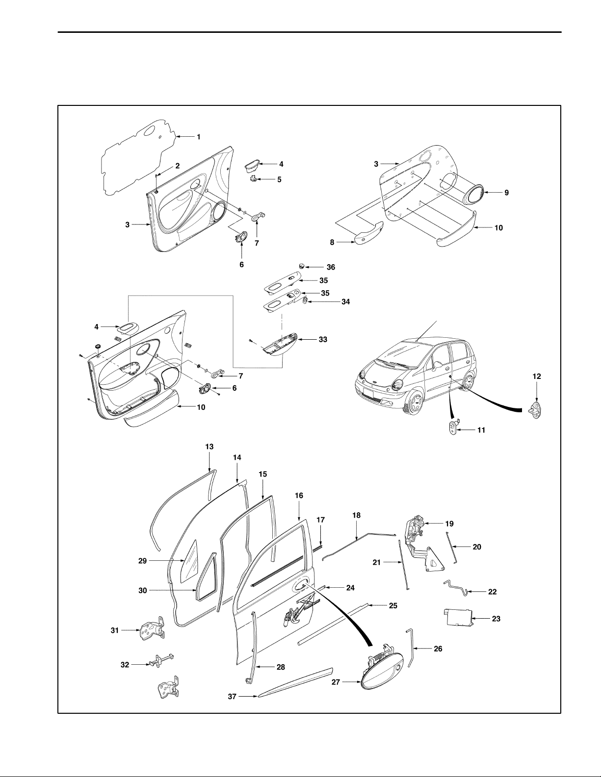
FRONT DOOR
DOORS 9P–3
DAEWOO M-150 BL2
D19C403A
Page 4

9P –4 DOORS
1. Seal Trim
2. Lock Button
3. Trim Panel
4. Pocket Handle (Deluxe Type)
5. Pocket Handle Bracket (Deluxe Type)
6. Inside handle
7. Manual Regulator Handle
8. Pocket Handle (Standard Type)
9. Door Speaker Cover
10. Map Pocket
11. Contact Switch
12. Striker
13. Opening Weatherstrip
14. Door Weatherstrip
15. Glass Run
16. Front Door
17. Inside Channel Weatherstrip
18. Inside Handle Rod
19. Door Lock
20. Door Lock Cylinder Rod
21. Lock Rod
22. Actuator Rod
23. Actuator
24. Window Regulator
25. Outside Channel Weatherstrip
26. Outside Handle Rod
27. Outside Handle
28. Division Bar
29. Quarter Glass
30. Quarter Glass Run
31. Door Hinge
32. Door Hold Open Link
33. Power Window Switch Cover
34. Mirror Switch
35. Power Window Switch Assembly
36. Mirror switch Blank
37. Door Side Molding
DAEWOO M-150 BL2
Page 5
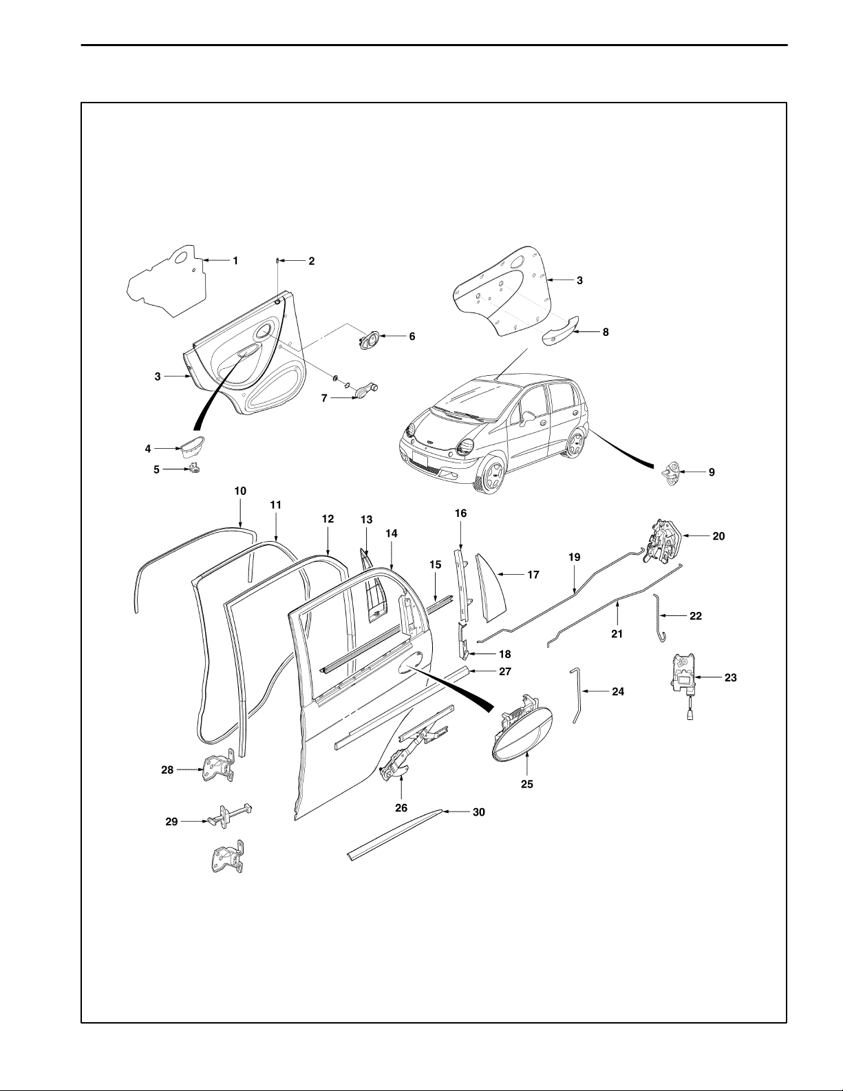
REAR DOOR
DOORS 9P–5
DAEWOO M-150 BL2
D19C404A
Page 6

9P –6 DOORS
1. Seal Trim
2. Lock Button
3. Trim Panel
4. Pocket Handle (Deluxe Type)
5. Pocket Handle Bracket (Deluxe Type)
6. Inside handle
7. Manual Regulator Handle
8. Pocket Handle (Standard Type)
9. Striker
10. Opening Weatherstrip
11. Door Weatherstrip
12. Glass Run
13. Interior Garnish Molding
14. Rear Door
15. Inside Channel Weatherstrip
16. Upper Guide Rail
17. Exterior Garnish Molding
18. Lower Guide Rail
19. Lock Rod
20. Door Lock
21. Inside Handle Rod
22. Actuator Rod
23. Actuator
24. Outside Handle Rod
25. Outside Handle
26. Window Regulator
27. Outside Channel Weatherstrip
28. Door Hinge
29. Door Hold Open Link
30. Door Side Molding
DAEWOO M-150 BL2
Page 7
REPAIR INSTRUCTIONS
ON–VEHICLE SERVICE
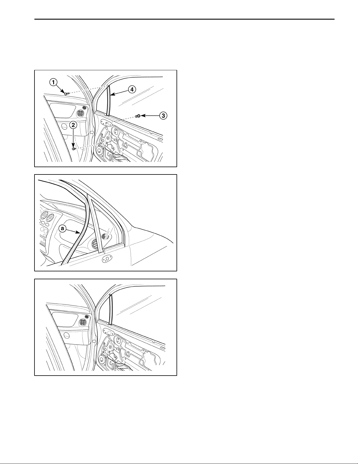
FRONT DOOR GLASS RUN
Removal Procedure
1. Remove the front door seal trim from the front door.
Refer to “Door Seal Trim” in this section.
2. Remove the outside rearview mirror from the front
door. Refer to Section 9L, Glass and Mirrors.
3. Remove the guide rail from the door.
D Remove the screws (1).
D Remove the inside bolts (2).
D Remove the outside bolts (3).
D109E521
D Remove the division bar (4).
4. Remove the glass run.
a. Glass run.
DOORS 9P–7
D109E522
D109E526
Installation Procedure
1. Install the glass run.
2. Install the division bar with the bolts and the screws.
3. Install the outside rearview mirror. Refer to Section
9L, Glass and Mirrors.
4. Install the front door seal trim. Refer to “Door Seal
Trim” in this section.
DAEWOO M-150 BL2
Page 8
9P –8 DOORS
D109C566
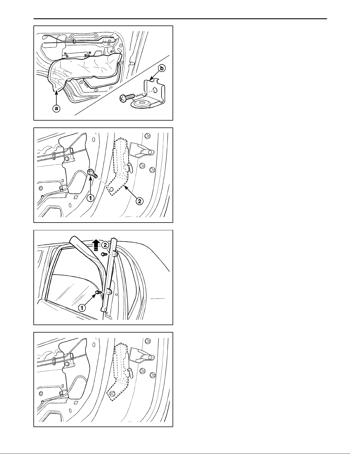
REAR DOOR GLASS RUN
Removal Procedure
1. Remove the inside channel weatherstrip from the
rear door. Refer to Section 9G, Interior Trim.
2. Remove the outside channel weatherstrip from the
rear doors. Refer to Section 9G, Interior Trim.
3. Remove the rear door trim panel. Refer to Section
9G, Interior Trim.
4. Remove the rear door seal trim.
a. Door seal trim.
b. Door pocket handle bracket.
Important: In case of the deluxe type, remove the seal
trim after removing the door pocket handle bracket.
5. Remove the guide piece.
D Remove the screw (1).
D Remove the guide piece (2).
D109C567
D109C568
D109C569
6. Remove the upper guide rail and the glass run.
D Remove the bolts (1).
D Lift up and remove the upper guide rail and the
glass run simultaneously (2).
Installation Procedure
1. Install the upper guide rail and the rear door glass
run.
2. Install the guide piece with the screw.
3. Install the rear door seal trim.
4. Install the rear door trim panel. Refer to Section 9G,
Interior Trim.
5. Install the outside channel weatherstrip to the rear
door. Refer to Section 9G, Interior Trim.
6. Install the inside channel weatherstrip to the rear
door. Refer to Section 9G, Interior Trim.
DAEWOO M-150 BL2
Page 9
D109C570
DOORS 9P–9
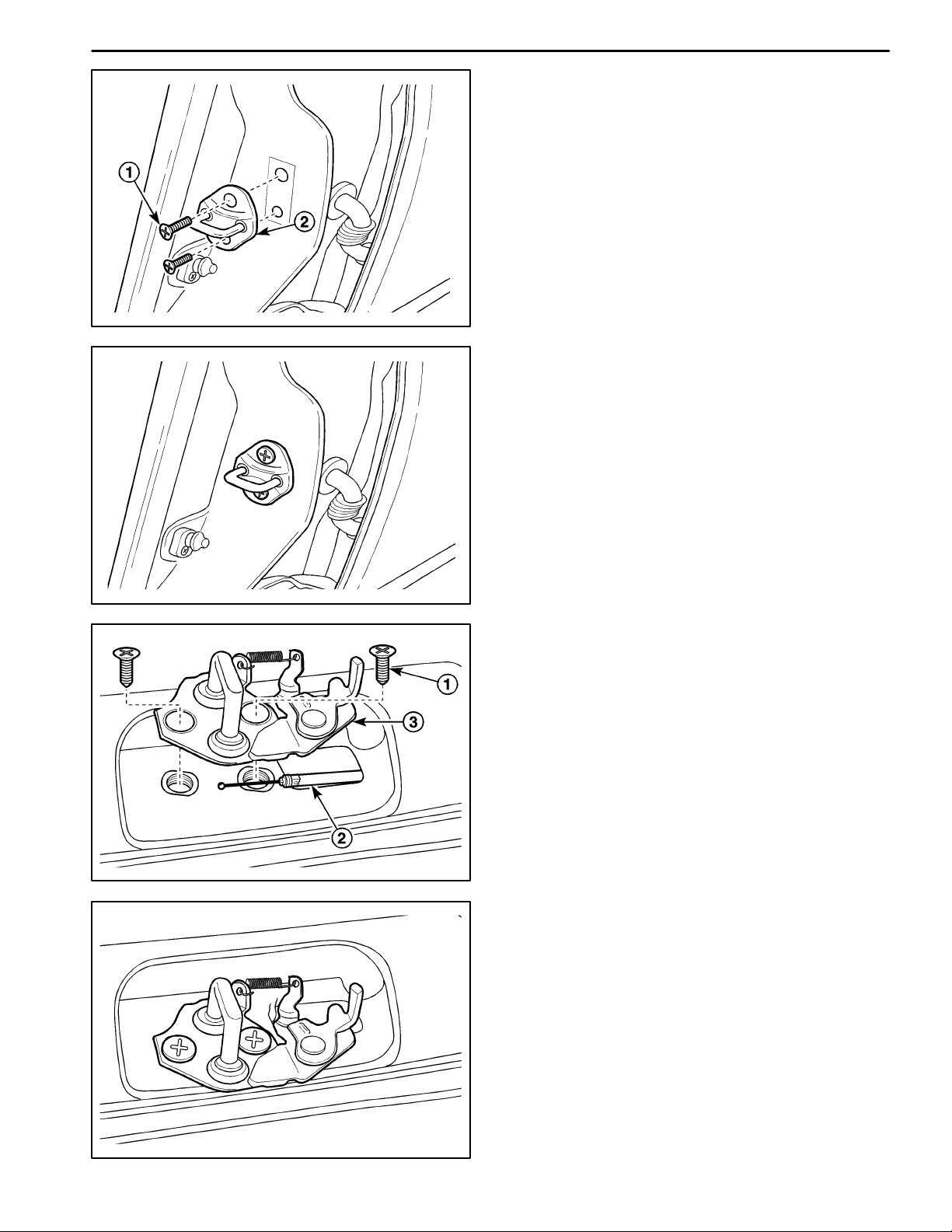
DOOR LOCK STRIKER
Removal Procedure
1. Remove the door lock striker.
D Remove the screws (1).
D Remove the door lock striker (2).
Installation Procedure
Notice: Dissimilar metals in direct contact with each
other may corrode rapidly. Make sure to use the correct
fasteners to prevent premature corrosion.
1. Install the door lock striker with the screws.
D109C571
D109C572
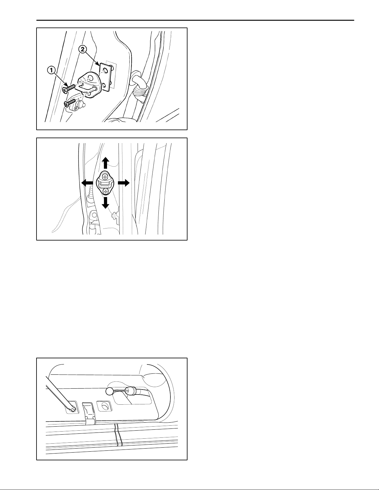
TAILGA T E LOCK STRIKER
Removal Procedure
1. Open the tailgate and suitably support it.
2. Remove the tailgate lock striker.
D Remove the screws (1).
D Disconnect the cable (2).
D Remove the striker (3).
Installation Procedure
Notice: Dissimilar metal in direct contact with each oth-
er may corrode rapidly. Make sure to use the correct fasteners to prevent premature corrosion.
1. Connect the cable.
2. Install the tailgate lock striker with the screws.
DAEWOO M-150 BL2
D109C573
Page 10
9P –10 DOORS
D109C574
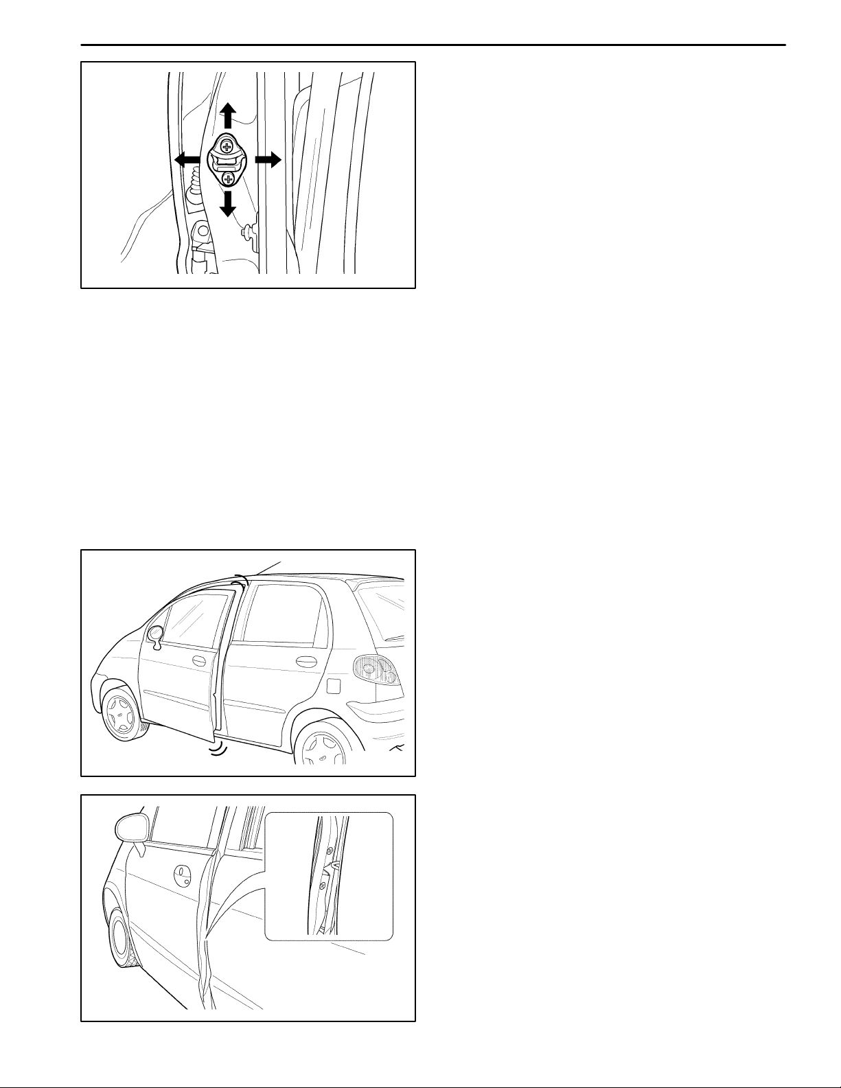
DOOR LOCK STRIKER ADJUSTMENT
Notice: The door lock striker is an important attaching
part that can affect the performance of vital components
and systems and can cause major repair expenses. If
replacement becomes necessary, the door lock striker
must be replaced by one with the same part number or
with an equivalent part if replacement becomes necessary. Do not use a replacement part of lesser quality or
of a substitute design. The specified torque values must
be used during reassembly in order to ensure the proper
retention of the part.
The door lock striker consists of a striker with two
screws that are threaded into a tapped, floating cage
plate located in the appropriate body pillar. This floating
cage plate allows the striker to be easily adjusted in or
out and up or down. The door is secured in the closed
position when the door lock fork snaps over and engages the striker.
D19C575A
Fore/Aft Adjustment
1. The door must be properly aligned.
2. Close the door until the lock fork contacts the striker.
3. Stand next to the door opening and move the door
slowly in and out, just touching the striker each time.
4. The alignment of the lock fork and the striker can be
easily seen. The lock fork should be perpendicular to
and fall near the middle of the striker. The lock fork
should fall near the middle of the striker between the
B-pillar and the end of the striker.
D109C576
DAEWOO M-150 BL2
Page 11
D109C577
D109C574
DOORS 9P–11
5. If a fore or aft adjustment is required, use the following
steps:
D Remove the striker screws (1).
D Remove the spacer in order to move the striker to-
ward the rear of the vehicle (2).
D Add a 2 mm (0.08 inch) spacer in order to move
the striker toward the front of the vehicle.
D Install the striker screws.
6. Perform the up/down or the in/out adjustment. Refer
to ‘‘Up/Down or In/Out Adjustment’’ in this section.
Up/Down or In/Out Adjustment
An adjustment of the striker in the up and down or in a n d
out directions may be necessary for a number of reasons:
vehicle frame dam age as the result o f a collision, inst alla tion of new door weatherstripping, customer complaints
of excessiv e windnoise, or difficulty in opening or closing
the door. In order to adjust the door striker in an up and
down or in and out direction, perf orm the following procedure:
1. The door must be properly aligned.
2. Loosen the striker screws.
3. The floating cage plate can be moved slightly using
the ends of the striker screws. Move the floating cage
plate to the desired position.
D109C578
Notice: It is important to use a flat-end rotary file in or-
der not to damage the tapped floating cage plate. The
striker screws and the tapped floating cage plate are important attaching parts that could affect the performance
of vital components and systems.
4. If proper adjustment requires that the floating cage plate
be moved more than is possible, use an electric hand
drill and a 3/8- inch rotary file with a flat head in order to
enlarge the body opening in the direction required.
5. Tighten the striker screws to the correct position.
TAILGA T E LOCK STRIKER
ADJUSTMENT
Notice: The tailgate lock striker is an important attaching
part that can affect the performance of vital components
and systems and can cause major repair expenses. If replacement becomes necessary, the tailgate lock striker
must be replaced by one with the same part number or
with an equivalent part if replacement becomes necessary. D o not use a replacement part of lesser quality or of
a substitute design. The specified torque values must be
used during reassembly in order to ensure the proper
retention of the part.
DAEWOO M-150 BL2
Page 12

9P –12 DOORS
D109C578
The tailgate lock striker consists of a striker with two
screws that are threaded into a tapped, floating cage
plate located in the appropriate body pillar. This floating
cage plate allows the striker to be easily adjusted in or
out and up or down. The tailgate is secured in the closed
position when the tailgate lock fork snaps over and engages the striker.
Fore/Aft or In/Out Adjustment
An adjustment of the striker in the fore and aft or in and
out directions may be necessary for a number of reasons:
vehicle frame dam age as the result o f a collision, inst alla tion of new tailgate weatherstripping, customer complaints of ex cessive windnoise, or difficult y in opening or
closing the tailgate. In order to adjust the tailgate striker in
an fore and aft or in and out direct ion, perf orm the following procedure:
1. The tailgate must be properly aligned.
2. Loosen the striker screws.
3. The floating cage plate can be moved slightly using
the ends of the striker screws. Move the floating cage
plate to the desired position.
Notice: It is important to use a flat-end rotary file in order not to damage the tapped floating cage plate. The
striker screws and the tapped floating cage plate are important attaching parts that could affect the performance
of vital components and systems.
4. If proper adjustment requires that the floating cage plate
be moved more than is possible, use an electric hand
drill and a 3/8- inch rotary file with a flat head in order to
enlarge the body opening in the direction required.
5. Tighten the striker screws to the correct position.
6. Perform the up/down adjustment. Refer to “Up and
Down Adjustment” in this section.
D109C579
DAEWOO M-150 BL2
Page 13

D19C580A
DOORS 9P–13
Up and Down Adjustment
1. The tailgate must be properly aligned.
2. Close the tailgate until the lock fork contacts the striker.
3. Stand next to the tailgate opening and move the tailgate slowly up and down, just touching the striker
each time.
4. The alignment of the lock fork and the striker can be
easily seen. The lock fork should be perpendicular to
and fall near the middle of the striker. The lock fork
should fall near the middle of the striker between the
rear body pillar and the end of the striker.
D109C581
D109C582
5. If a up and down adjustment is required, use the following steps:
D Remove the striker screws (1).
D Remove the spacer in order to move the striker to-
ward the down of the vehicle (2).
D Add a 2 mm (0.08 inch) spacer in order to move
the striker toward the up of the vehicle.
D Install the striker screws.
FRONT DOOR LOCK
Removal Procedure
1. Disconnect the negative battery cable if equipped
with the central door lock system.
2. Remove the seal trim. Refer to “Door Seal Trim” in
this section.
3. Disconnect the outside door handle rod from the door
lock.
a. Outside door handle rod.
b. Key rod.
DAEWOO M-150 BL2
D19C583A
Page 14

9P –14 DOORS
D109C584
D109C585
4. Remove the front door lock.
D Remove the screws (1).
D Remove the front door lock (2).
Important: Disconnect the actuator connector, if
equipped with the central door lock system.
Installation Procedure
Notice: Dissimilar metals in direct contact with each
other may corrode rapidly. Make sure to use the correct
fasteners to prevent premature corrosion.
1. Install the front door lock with screws.
Important: Connect the actuator connector if equipped
with the central door lock system.
2. Connect the outside door handle rod and the key rod
to the door lock.
3. Install the seal trim. Refer to “Door Seal Trim” in this
section.
4. Connect the negative battery cable, if equipped with
the central door lock system.
D109C566
CHILDPROOF REAR DOOR LOCK
Removal Procedure
1. Disconnect the negative battery cable if equipped
with the central door lock system.
2. Remove the door trim panel. Refer to Section 9G, In-
terior Trim.
3. Remove the door seal trim. Refer to “Door Seal Trim”
in this section.
a. Door seal trim.
b. Door pocket handle bracket.
Important: In case of the deluxe type, remove the seal
trim after removing the door pocket handle bracket.
4. Remove the guide piece.
D Remove the screw (1).
D Remove the guide piece (2).
D109C567
DAEWOO M-150 BL2
Page 15

D109C583
DOORS 9P–15
5. Disconnect the outside door handle rod from the door
lock.
a. Outside door handle rod.
6. Disconnect the door lock from the vehicle.
D Remove the screws (1).
D Remove the door lock (2).
Important: Disconnect the actuator connector if
equipped with the central door lock system.
D109C586
D109C587
Installation Procedure
Notice: Dissimilar metals in direct contact with each
other may corrode rapidly. Make sure to use the correct
fasteners to prevent premature corrosion.
1. Install the rear door lock with the screws.
Important: Connect the actuator connector if equipped
with the central door lock system.
2. Connect the outside door handle rod to the door lock.
3. Install the guide rail with the screw.
4. Install the seal trim. Refer to “Door Seal Trim” in this
section.
5. Install the door trim panel. Refer to Section 9G, Interi-
or Trim.
6. Connect the negative battery cable if equipped with
the central door lock system.
DAEWOO M-150 BL2
Page 16

9P –16 DOORS
CENTRAL DOOR LOCK ACTUATOR
Removal Procedure
1. Disconnect the negative battery cable.
2. Remove the door seal trim. Refer to “Door Seal T rim”
in this section.
3. Remove the door lock assembly. Refer to “Door Lock”
in this section.
4. Remove the actuator from the door lock assembly.
D Remove the screws (1).
D Remove the actuator (2).
D109C588
Installation Procedure
1. Install the door lock actuator to the door lock assembly with the screws.
2. Install the door lock assembly to the vehicle. Refer to
“Door Lock” in this section.
3. Install the door seal trim. Refer to “Door Seal Trim” in
this section.
4. Connect the negative battery cable.
D109C589
D109C590
TAILGATE LOCK
Removal Procedure
1. Remove the tailgate trim panel. Refer to Section 9G,
Interior Trim.
2. Remove the lock rod from the tailgate lock cylinder.
a. Lock rod.
3. Remove the tailgate lock.
D Remove the screws (1).
D Remove the tailgate lock (2).
D109C591
DAEWOO M-150 BL2
Page 17

D109C592
DOORS 9P–17
Installation Procedure
1. Install the tailgate lock with the screws.
2. Install the lock rod to the tailgate lock cylinder.
3. Install the tailgate trim panel. Refer to Section 9G, In-
terior Trim .
INSIDE DOOR HANDLE
Removal Procedure
1. Removal the inside door handle.
D Remove the screw (1).
D Remove the inside door handle (2).
D109C593
D109C594
Installation Procedure
1. Install the inside door handle with the screw.
OUTSIDE FRONT DOOR HANDLE
Removal Procedure
1. Disconnect the negative battery cable.
2. Remove the front door lock rods.
3. Remove the outside front door handle.
D Remove the bolts (1).
D Remove the outside front door handle (2).
DAEWOO M-150 BL2
D109C595
Page 18

9P –18 DOORS
Installation Procedure
1. Install the outside front door lock handle with the
bolts.
2. Install the front door lock rods.
3. Connect the negative battery cable.
D109C596
OUTSIDE REAR DOOR HANDLE
Removal Procedure
1. Disconnect the negative battery cable.
2. Remove the rear door lock. Refer to “Childproof Rear
Door Lock” in this section.
3. Remove the outside rear door handle.
D Remove the bolts (1).
D Remove the outside rear door handle (2).
D109C597
D109C598
Installation Procedure
1. Install the outside rear door handle with the bolts.
2. Install the rear door lock. Refer to “Childproof Rear
door Lock” in this section.
3. Connect the negative battery cable.
DOOR LOCK CYLINDER
Removal Procedure
1. Disconnect the negative battery cable.
2. Remove the outside door handle. Refer to “Outside
Front Door Handle” in this section.
3. Remove the door lock cylinder from the outside door
handle.
D Remove the clip (1).
D Remove the door lock cylinder (2).
D109C599
DAEWOO M-150 BL2
Page 19

D109C600
DOORS 9P–19
Installation Procedure
1. Install the door lock cylinder with the clip.
2. Install the outside door handle. Refer to “Outside
Front Door Handle” in this section.
3. Connect the negative battery cable.
MANUAL WINDOW REGULATOR
Removal Procedure
1. Remove the glass. Refer to Section 9L, Glass and
Mirrors.
2. Remove the window regulator.
D Remove the screws (1).
D Remove the regulator (2).
D109C601
D109C602
D109C603
Installation Procedure
1. Install the regulator with the screws.
2. Install the glass. Refer to Section 9L, Glass and Mir-
rors.
POWER FRONT WINDOW
REGULATOR
Removal Procedure
1. Disconnect the negative battery cable.
2. Remove the glass. Refer to Section 9L, Glass and
Mirrors.
3. Remove the window regulator assembly.
D Disconnect the window motor electrical connector
(1).
D Remove the screws (2).
D Remove the window regulator assembly (3).
DAEWOO M-150 BL2
Page 20

9P –20 DOORS
4. Remove the window motor from the window regulator.
D Remove the screws (1).
D Remove the window regulator (2).
Caution: Be careful what you are doing when separating the window motor and the window regulator.
You may be hurt.
D109C604
Installation Procedure
1. Install the window motor to the window regulator with
the screws.
2. I nst all the window regulator assembly with the screws.
3. Connect the window motor electrical connector.
4. Install the glass. Refer to Section 9L, Glass and Mir-
rors.
5. Connect the negative battery cable.
D109C605
D109C606
FRONT DOOR ASSEMBLY
Removal Procedure
1. Disconnect the negative battery cable.
2. Disconnect the electrical connector under the instrument panel.
Important: In case of the front passenger door, remove
the glove box in advance.
3. Remove the fender. Refer to Section 9R, Body Front
End.
4. Remove the front door assembly.
D Remove the door hinge bolts (1).
D Remove the door hold open bolt (2).
D Disconnect the body–to–door rubber grommet (3).
D Remove the front door assembly (4).
D109C607
DAEWOO M-150 BL2
Page 21

D19C608A
DOORS 9P–21
Installation Procedure
Notice: Dissimilar metals in direct contact with each
other may corrode rapidly. Make sure to use the correct
fastener to prevent premature corrosion.
1. Connect the body–to–door rubber grommet.
2. With the aid of another technician, lightly secure the
front door with the bolts.
3. Adjust the door for proper fit.
4. Tighten the hinge–to–body bolts.
5. Install the door hold open link with the bolt.
6. Install the fender. Refer to Section 9R, Body Front
End.
7. Connect the electrical connector.
8. Connect the negative battery cable.
9. Perform the waterleak test. Refer to Section 9I, Wa-
terleak.
10. Check for windnoise. Refer to Section 9J, Windnoise.
D109C609
REAR DOOR ASSEMBLY
Removal Procedure
1. Disconnect the negative battery cable.
2. Pry off the lower B–pillar trim panel. Refer to Section
9G, Interior Trim.
3. Disconnect the rear door electrical connector.
a. Rear door electrical connector.
4. Remove the rear door assembly.
D Remove the door hinge bolts (1).
D Remove the door hold open link bolt (2).
D Disconnect the body–to–door rubber grommet (3).
D Remove the rear door assembly (4).
DAEWOO M-150 BL2
D109C610
Page 22

9P –22 DOORS
D19C611A
Installation Procedure
Notice: Dissimilar metals in direct contact with each
other may corrode rapidly. Make sure to use the correct
fastener to prevent premature corrosion.
1.Connect the body–to–door rubber grommet.
2. With the aid of another technician, lightly secure the
rear door with the bolts.
3. Adjust the door for proper fit.
4. Install the door hold open link with the bolt.
5. Connect the rear door electrical connector.
6. Connect the negative battery cable.
7. Perform the waterleak test. Refer to Section 9I, Wa-
terleaks.
8. Check for windnoise. Refer to Section 9J, Windnoise.
TAILGATE
Removal Procedure
1. Disconnect the negative battery cable.
2. Remove the luggage compartment wheelhouse trim
panel. Refer to Section 9G, Interior Trim.
3. Disconnect the tailgate electrical connector.
a. Tailgate electrical connector.
D109C612
D109C636
4. Remove the tailgate strut. Refer to “Tailgate Strut” in
this section.
5. Remove the tailgate.
D Remove the hinge bolts.
D Disconnect the body–to–tailgate rubber grommet.
D Remove the tailgate.
D19C613A
DAEWOO M-150 BL2
Page 23

D19C614A
D209B113
DOORS 9P–23
Installation Procedure
Notice: Dissimilar metals in direct contact with each
other may corrode rapidly. Make sure to use the correct
fastener to prevent premature corrosion.
1. Connect the body–to–tailgate rubber grommet.
2. With the aid of another technician, lightly secure the
tailgate with the bolts.
3. Adjust the tailgate for proper fit.
4. Inst all the tailgate strut. Refer to “Tailgate Strut” in this
section.
5. Connect the tailgate electr ical connect or.
6. I nstall the luggage compart ment wheelhouse trim pan -
el. Refer to Section 9G, Interior Trim.
7. Connect the negative battery cable.
TAILGATE LOCK CYLINDER
Removal Procedure
1. Disconnect the negative battery cable.
2. Open the tailgate.
3. Remove the rear window wiper motor assembly. Re-
fer to Section 9D, Wipers/Washer Systems.
4. Remove the tailgate lock cylinder.
D Disconnect the tailgate lock rod (1).
D Remove the nuts from the tailgate lock cylinder (2).
D Remove the tailgate lock cylinder (3).
D209B114
Installation Procedure
1. Install the tailgate lock cylinder.
2. Install the rear window wiper motor assembly. Refer
to Section 9D, Wipers/Washer Systems.
3. Connect the negative battery cable.
DOOR HINGE
Removal Procedure
1. With the aid of another technician, remove the door
hinge.
D Remove the hinge–to–body bolts (1).
D Remove the hinge–to–door bolts (2).
D Remove the door hinge (3).
DAEWOO M-150 BL2
D109C615
Page 24

9P –24 DOORS
Installation Procedure
Notice: Dissimilar metals in direct contact with each
other may corrode rapidly. Make sure to use the correct
fastener to prevent premature corrosion.
1. With the aid of another technician, install the hinge to
the door and the body with the bolts.
D109C616
DOOR HOLD OPEN LINK
Removal Procedure
1. Remove the door seal trim. Refer to “Door Seal T rim”
in this section.
2. Remove the door hold open link.
D Remove the hinge–to–body bolt (1).
D Remove the hinge–to–door bolts (2).
D Remove the door hold open link (3).
D109C617
D109C618
Installation Procedure
Notice: Dissimilar metals in direct contact with each
other may corrode rapidly. Make sure to use the correct
fastener to prevent premature corrosion.
1. Install the door hold open link to the door and the
body with the bolts.
2. Remove the door seal trim. Refer to “Door Seal T rim”
in this section.
INSIDE CHANNEL WEATHERSTRIP
(STANDARD)
Removal Procedure
1. Remove the channel weatherstrip.
a. Weatherstrip.
D109C619
DAEWOO M-150 BL2
Page 25

D109C620
DOORS 9P–25
Installation Procedure
1. Install the channel weatherstrip.
INSIDE CHANNEL WEATHERSTRIP
(DELUXE)
Removal Procedure
1. Remove the door trim. Refer to Section 9G, Interior
Trim.
2. Remove the channel weatherstrip from the door trim.
D Straighten the retaining tabs (1).
D Remove the channel weatherstrip (2).
D109C621
D109C622
Installation Procedure
1. Install the channel weatherstrip onto the door trim
panel.
2. Bend the retaining tabs to secure the channel weath-
erstrip to the door trim panel.
3. Install the door trim panel. Refer to Section 9G, Interi-
or Trim.
DOOR OUTSIDE CHANNEL
WEATHERSTRIP
Removal Procedure
1. Remove the channel weatherstrip.
D Remove the screw (1).
D Lift off the outside channel weatherstrip (2).
DAEWOO M-150 BL2
D109C623
Page 26

9P –26 DOORS
Installation Procedure
1. Press the outside channel weatherstrip onto the door.
2. Install the weatherstrip screw.
D109C624
DOOR WEATHERSTRIP
Removal Procedure
1. Remove the door hold open link bolt.
D109C625
D109C626
2. Remove the door weatherstrip.
D Remove the clip (1).
D Remove the weatherstrip pins (2).
Installation Procedure
1. Install the door weatherstrip with the clip and the pins.
2. Install the door hold open link bolt.
D109C627
DAEWOO M-150 BL2
Page 27

D109C566
DOORS 9P–27
DOOR SEAL TRIM
Removal Procedure
1. Remove the door trim panel. Refer to Section 9G, In-
terior Trim.
2. Remove the door seal trim.
a. Door seal trim.
b. Door pocket handle bracket.
Important: In case of the deluxe trim, remove the door
pocket handle bracket in advance.
Installation Procedure
1. Install the door seal trim.
2. Install the door pocket handle bracket for the deluxe
trim.
3. Install the door trim panel. Refer to Section 9G, Interi-
or Trim.
D109C628
D109C629
DOOR OPENING WEATHERSTRIP
Removal Procedure
1. Mark the door opening weatherstrip edge by a soluble
pen.
2. Remove the door opening weatherstrip.
D Take off the rocker trim panel partially (1).
D Take off the lower B–pillar trim panel partially (2).
D Remove the door opening weatherstrip (3).
DAEWOO M-150 BL2
D109C630
Page 28

9P –28 DOORS
Installation Procedure
1. Install the door opening weatherstrip to match the
marking.
2. Install the rocker panel trim and the lower B–pillar
panel trim.
D109C631
MANUAL WINDOW REGULATOR
HANDLE
Removal Procedure
1. Remove the window regulator handle.
D Using a cloth, pull out the clip (1).
D Remove the window regulator handle (2).
D109E543
D109C632
Installation Procedure
1. Install the window regulator handle with the clip.
TAILGATE STRUT
Removal Procedure
1. Open the tailgate and suitably support it.
2. Remove the tailgate strut assembly.
D Remove the end fitting nut from the ball studs (rear
body) (1).
D Removethe end fitting nut from the ball studs (tail-
gate) (2).
D19C634A
DAEWOO M-150 BL2
Page 29

D19C635A
DOORS 9P–29
Installation Procedure
1. Install the tailgate strut with the ball studs.
DAEWOO M-150 BL2
Page 30

9P –30 DOORS
SCHEMATIC AND ROUTING DIAGRAMS
POWER DOOR LOCKS
(LEFT–HAND DRIVE)
D19C201B
DAEWOO M-150 BL2
Page 31

POWER DOOR LOCKS
(RIGHT–HAND DRIVE)
DOORS 9P–31
DAEWOO M-150 BL2
D19C201S
Page 32

9P –32 DOORS
POWER DOOR LOCKS
(W/ ANTI–THEFT CONTROL : LHD)
D19C201S
DAEWOO M-150 BL2
Page 33

POWER DOOR LOCKS
(W/ ANTI–THEFT CONTROL : RHD)
DOORS 9P–33
DAEWOO M-150 BL2
D19C202S
Page 34

9P –34 DOORS
POWER WINDOWS (FRONT ONLY)
D19C202B
DAEWOO M-150 BL2
 Loading...