

Page 1
Document # PG05-009
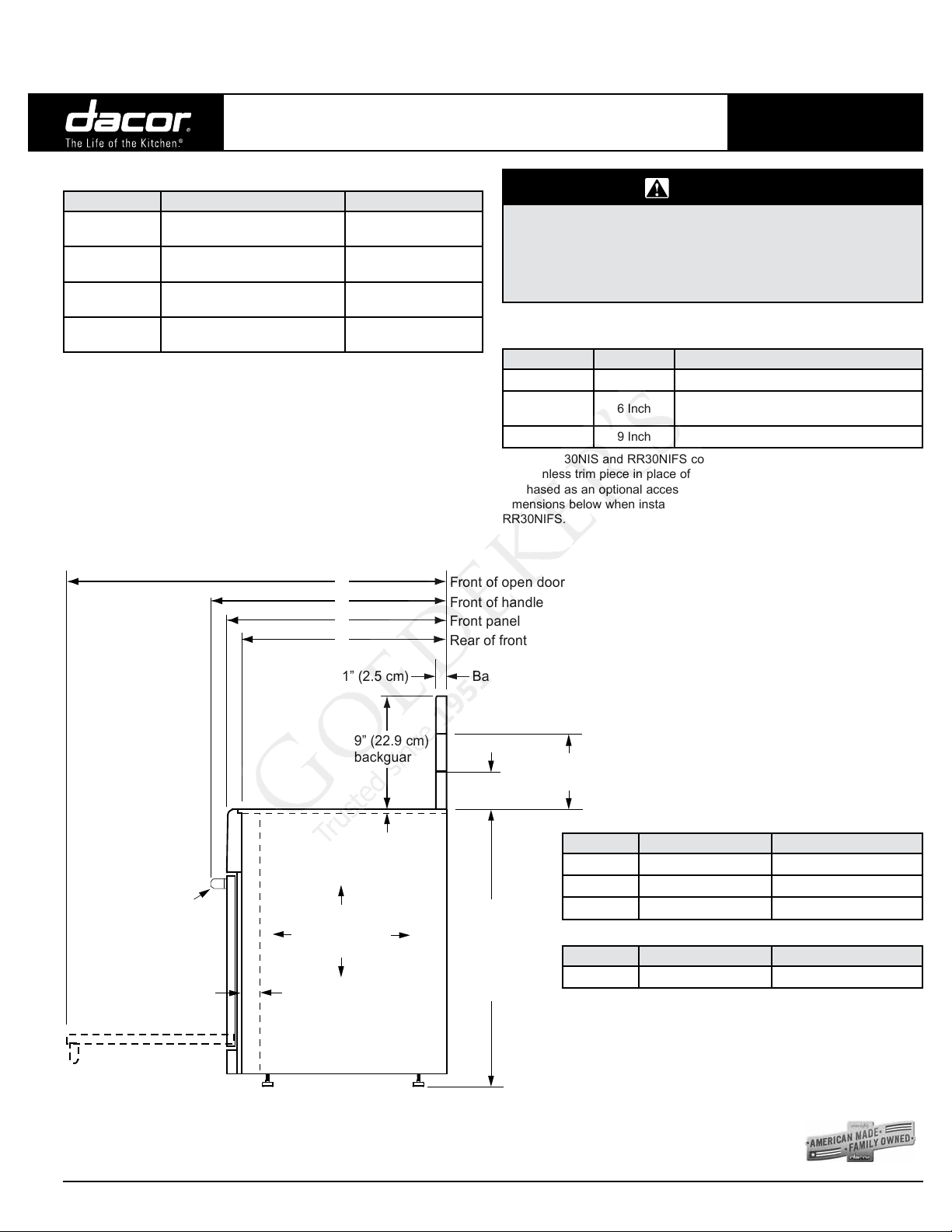
1” (2.5 cm)
Front of open door
Front of handle
Front panel
Rear of front panel
Backguard thickness
3” (7.6 cm)
backguard*
External handle
shown, some models
have integral handle
(see inside cover)�
6” (15.2 cm)
backguard*
*�
See table for compatibility
Product width:
29 15/16” (76.0 cm)
35”
(88.9 cm)
to
37”
(94.0 cm)
9” (22.9 cm)�
backguard*
A
B
C
D
RR30NI[F]S:
3/8” (9.5 mm)
thick top trim
RR30N[F]S:
full stainless
steel side panels
RR30NI[F]S:
3” (7.6 cm)
partial stainless
steel side panels
(removable)
RR30NS, RR30NFS, RR30NIS, RR30NIFS
Revised 05/23/13 Page 1/5
Renaissance® 30” Wide
Electric Inductive Range
Model Versions
Model Configuration Handle Type
RR30NS[-C]*
RR30NFS[-C]*
RR30NIS[-C]*
RR30NIFS[-C]*
* Order -C option for corded wiring configuration, see page 3/5 for details.
Freestanding,
(full size side panels)
Freestanding,
(full size side panels)
Built-in/Slide-in
(3 1/4” removable side panels)
Built-in/Slide-in
(3 1/4” removable side panels)
Product Dimensions
All tolerances ±1/16” (±1.6 mm) unless otherwise noted.
Mounted on
outside of door
Flush handle,
integrated in door
Mounted on
outside of door
Mounted on
outside of door
PLANNING
GUIDE
WARNING
• Observe all governing codes and ordinances during planning
and installation. Contact your local building department for
further information.
• This appliance must be installed in accordance with the
accompanying installation instructions.
Available Backguards
Part Number Description Compatibility
ADRB30E03 3 Inch Optional on all models
ADRB30E06 6 Inch
ADRB30E09 9 Inch Optional on all models
Models RR30NIS and RR30NIFS come equipped from the factory with
flat stainless trim piece in place of a backguard. A backguard may be
purchased as an optional accessory. Add an additional 1/16 inch to depth
dimensions below when installing a backguard on models RR30NIS and
RR30NIFS.
Standard on models RR30NS, RR30NFS
Optional on models RR30NIS, RR30NIFS
OVERALL DEPTH DIMENSIONS - SIDE VIEW
All specications subject to change without notice.
Dimension RR30NS, RR30NFS RR30NIS, RR30NIFS
A 46 1/4” (117.5 cm) 46 1/16” (117.0 cm)
C 25 1/2” (64.8 cm) 25 5/16” (64.3 cm)
D 23 3/8” (59.4 cm) 23 3/16” (58.9 cm)
Dimension RR30NS RR30NIS
B 27 7/8” (70.8 cm) 27 11/16” (70.3 cm)
The trim on models RR30NS and RR30NFS are not compatible
with a raised vent.
Models RR30NIS and RR30NIFS are compatible with Dacor
raised vent models ERV30 and ERV3015. Use only these
specified raised vent models.
Phone: (800) 793-0093www.dacor.com
Page 2
Document # PG05-009
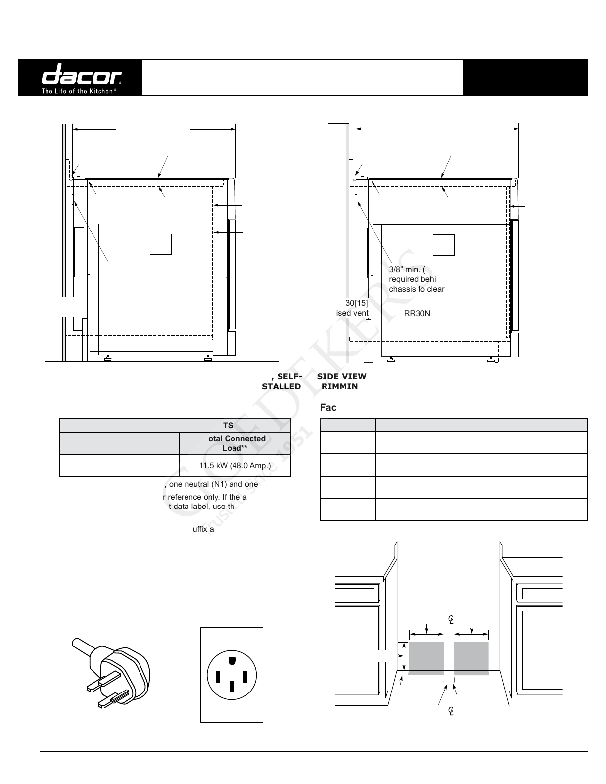
Cabinet face
Countertop
Range trim resting
on countertop
RR30NI[F]S range
3/8” min. (1.0 cm)
flat countertop
overhang
27 9/16” (70.0 cm)
ERV30[15]
raised vent
3/8” min. (1.0 cm) space
required behind ERV30[15]
chassis to clear stiffener
ATKR30SR
trim kit
installed
Cabinet face
Countertop
Range trim resting
on countertop
Back of
side panel
rests against
cabinet face
RR30NI[F]S range
3/8” min. (1.0 cm)
flat countertop
overhang
ATKR30SR
trim kit
installed
27 9/16” (70.0 cm)
3 inch
side panel
ERV30[15]
raised vent
3/8” min. (1.0 cm) space
required behind ERV30[15]
chassis to clear stiffener
RR30NS, RR30NFS, RR30NIS, RR30NIFS
Revised 05/23/13 Page 2/5
Product Dimensions (cont.)
Renaissance 30” Wide
Electric Inductive Range
PLANNING
GUIDE
SIDE VIEW - DOWNDRAFT ERV30[15] WITH SLIDE-IN, SELF-
RIMMING INSTALLATION WITH 3” SIDE PANELS INSTALLED
Electrical Specifications
ELECTRICAL REQUIREMENTS
Electrical Circuit
Required
240 Vac 60 Hz, 4 wire*,
50 Amp.
*Two 120 Vac hot (L1 and L2), one neutral (N1) and one ground.
**This information above is for reference only. If the above data
does not agree with the product data label, use the data on the
product data label.
IMPORTANT: Models with -C option suffix are ranges that
come with a factory installed 4-wire appliance cord with NEMA
14-50P plug. For freestanding ranges installed in Canada, a
factory installed 4-wire appliance cord with NEMA 14-50P plug
is required, without modification. For slide-in ranges installed in
Canada and all ranges installed outside of Canada, the 4-wire
appliance cord configuration (-C type) is optional and may be
utilized where local codes permit The plug is designed to plug
directly into a NEMA 14-50R electrical receptacle installed by a
licensed electrician according to the above specifications.
NEMA 14-50P PLUG NEMA 14-50R RECEPTACLE
Total Connected
Load**
11.5 kW (48.0 Amp.)
SIDE VIEW - DOWNDRAFT ERV30[15] WITH SLIDE-IN, SELF-
RIMMING INSTALLATION WITH 3” SIDE PANELS REMOVED
Factory Wiring
Model Factory Electrical Connection
RR30NS,
RR30NFS
RR30NS-C,
RR30NFS-C
RR30NIS,
RR30NIFS
RR30NIS-C,
RR30NIFS-C
12” (30.5 cm)
Power cord not installed. Not for installation in Canada.
Cord connected, for installation in Canada (and U.S.A.,
No power cord. May be installed in Canada and U.S.A.
Cord connected, may be installed in Canada and U.S.A.,
2 1/2”
(6.4 cm)
UTILITY CLEARANCE BEHIND RANGE
where local codes permit).
where local codes permit.
10” (25.4 cm)
3 1/2”
(8.9 cm)
10” (25.4 cm)
1” (2.5 cm)
All specications subject to change without notice.
Phone: (800) 793-0093www.dacor.com
Page 3

Document # PG05-009
RR30NS, RR30NFS, RR30NIS, RR30NIFS
Revised 05/23/13 Page 3/5
Renaissance 30” Wide
Electric Inductive Range
All tolerances +1/16” (+1.6 mm), -0 unless otherwise noted.
B
13” (33.0 cm)
4
max.
18” (45.7 cm)
min.
Note 2
4
Non-combustible
surface along
back wall
recommended
Note 1
A
Suggested
location of
3
utilities
Top of
finished
counter
Note 5
PLANNING
GUIDE
■ Failure to meet or exceed the maximum and
minimum dimensions/clearances stated may result
in a fire hazard.
■ The shaded area shown denotes the location of
the electrical junction box/receptacle. This is the
suggested location. For replacement purposes, the
location of the existing electrical supply may be
utilized provided that it does not interfere with the
sides or rear of the range.
■ Access to the remote circuit breaker panel/fuse box,
with the range in place and operating, must also be
allowed for in the installation.
■ The electrical junction box/receptacle must be
located so that it does not interfere with the range
when it is installed and under operation. In addition,
the junction box/receptacle must be located so
the range can be removed for service and remain
connected to power.
■ To eliminate the risk of burns or fire by reaching
over heated surface units, cabinet storage space
located above surface units should be avoided. If
cabinet storage space is to be provided directly
above the range, the risk of personal injury may be
reduced by installing a range hood.
■ In all instances, installation of a range hood is highly
recommended. The hood should project horizontally
a minimum of five (5) inches beyond the face of
the cabinets. See the range hood specifications for
minimum clearances.
■ The range may be installed flush to the rear wall.
See diagram and notes for rear wall surface
requirements. It is not necessary to install noncombustible materials behind the range below the
countertop height.
■ Any openings in the wall behind the appliance or in
the floor underneath it must be sealed.
C
A* B
30 1/16” min.
(76.4 cm)
* See the cutout dimensions on following page for self-rimming installations.
FREESTANDING INSTALLATION CABINET CUTOUT DIMENSIONS - MODELS RR30NS, RR30NFS, RR30NIS AND RR30NIFS
1
30” (76.2 cm) min. vertical clearance from top of range grates to bottom of uncovered wood or metal cabinet. 24” (61 cm) min. clearance if bottom of wood
or metal cabinets are protected by not less than 1/4“ (0.6 cm) flame retardant millboard covered with no less than No. 28 MSG sheet steel 0.015” (0.04
cm) stainless steel, or 0.024” (0.06 cm) aluminum or 0.020” (0.05cm) copper. If installing range hood, check the hood specifications for minimum required
clearances.
2
Cabinet/countertop depth is at discretion of customer but cabinet face SHALL NOT protrude further than rear of front panel. See Product Dimensions.
3
Consult local code and following pages for requirements.
4
This specification not applicable for cabinets more than a horizontal distance of 1” (2.6 cm) min from edge of range.
5
1” (2.6 cm) min. to combustible sidewalls above range (both sides).
All specications subject to change without notice.
36” (91.4 cm) recommended
30” (76.2 cm) min.
C
37” (94.0 cm)
max.
Phone: (800) 793-0093www.dacor.com
Page 4

Document # PG05-009
Rear wall or
countertop edge
countertop opening
29 1/4” (74.3 cm)
30 1/16” (76.2 cm)
cabinet opening
below countertop
below countertop
Cabinet face
Notch countertop
to width of cabinets
3/8” min. (9.5 mm)
countertop overhang
1” min. (2.6 cm)
to any combustibles
above counter both sides
20”
(50.8 cm)
to
23”
(58.4 cm)
20”
(50.8 cm)
24 5/8”
(62.5 cm)
max.
Countertop front
Rear wall or
countertop edge
countertop opening
29 1/4” (74.3 cm)
30 1/16” (76.2 cm)*
cabinet opening
below countertop
below countertop
Cabinet face
Notch countertop
to width of cabinets
3/8” min. (9.5 mm)
countertop overhang
1” min. (2.6 cm)
to any combustibles
above counter both sides
23”
(58.4 cm)
24 5/8”
(62.5 cm)
max.
Countertop front
Cut 3” dia. (7.6 cm) holes
at back bottom of cabinet
for ventilation.
Provide ventilation through
cabient both sides,
7 square inches min.
Location may vary.
34 3/4”
to
36 7/8”
(see diagrams)
Countertop
1 5/8 (41.1 cm)
max. thickness
RR30NS, RR30NFS, RR30NIS, RR30NIFS
Revised 05/23/13 Page 4/5
Renaissance 30” Wide
Electric Inductive Range
Cabinet Cutouts for Self-Rimming Installation (Models RR30NIS and RR30NIFS Only)
All tolerances +1/16” (+1.6 mm), -0 unless otherwise noted.
Countertop height: 34 3/4” (88.3 cm) min.
36 7/8” (93.7 cm) max.
Countertop thickness: 1 5/8” (4.1 cm) max.
■ The self-rimming installation of the RR30NI[F]S range creates a
“built-in” look where the range trim overlaps the countertop on both
sides and in back.
■ IMPORTANT: When installing the range in this configuration,
ventilation must be provided to allow for cooling of the ranges
internal components. See diagram, left.
■ Observe all vertical cabinet clearances on page 3/5.
■ On self-rimming installations when sliding the range into position, it
will stop when the rear of the control panel or side panels contact the
notches toward the front of the countertop.
PLANNING
GUIDE
All specications subject to change without notice.
TOP VIEW - SLIDE-IN, SELF-RIMMING INSTALLATION,
3” SIDE PANELS INSTALLED
TOP VIEW - SLIDE-IN, SELF-RIMMING INSTALLATION,
3” SIDE PANELS REMOVED
* To create a “built-in look” on the front of the cabinet, this
dimension may be changed to 29 1/4” (74.3 cm), with the
width at the notches remaining 30 1/16”. This configuration
is only for models RR30NIS and RR30NIFS with side panels
behind door removed.
Phone: (800) 793-0093www.dacor.com
Page 5

Document # PG05-009
Rear wall or
countertop edge
countertop opening
29 1/4” (74.3 cm)
raised vent opening
27 1/2” (69.9 cm)
30 1/16” (76.2 cm)*
cabinet opening
below countertop
below countertop
Cabinet face
Notch countertop
to width of cabinets
3/8” min. (1.0 cm)
countertop overhang
1” min. (2.6 cm)
to any combustibles
above counter both sides
23 3/8”
(59.4 cm)
2 5/8” (6.7 cm)
25”
(63.5 cm)
max.
Countertop front
RR30NS, RR30NFS, RR30NIS, RR30NIFS
Revised 05/23/13 Page 5/5
Renaissance 30” Wide
Electric Inductive Range
Cabinet Cutouts for Self-Rimming Installation (Models RR30NIS and RR30NIFS Only)
All tolerances +1/16” (+1.6 mm), -0 unless otherwise noted.
Countertop
1 5/8 (41.1 cm)
max. thickness
34 3/4”
(88.3 cm)
to
36 7/8”
(93.7 cm)
(see diagrams)
Cut 3” dia. (7.6 cm) holes
at back bottom of cabinet
for ventilation.
Provide ventilation through
cabient both sides,
7 square inches min.
Location may vary.
Countertop height: 34 3/4” (88.3 cm) min.
36 7/8” (93.7 cm) max.
Countertop thickness: 1 5/8” (4.1 cm) max.
■ Trim kit PN ATKR30SR is required for proper installation of a raised
vent with this range.
■ The self-rimming installation of the RR30NI[F]S range and ERV30[15]
raised vent create a “built-in” look where the range trim overlaps
the countertop on both sides and the raised vent trim overlaps the
countertop in back. The ATKR30SR trim kit, installed on the back of
the range, will cover the front of the raised vent chassis.
■ IMPORTANT: When installing the range in this configuration,
ventilation must be provided to allow for cooling of the ranges
internal components. See diagram, left.
■ Observe all vertical cabinet clearances on page 3/5.
■ A self-rimming countertop configuration is required for raised vent
installation. On installations with a raised vent, when sliding the
range into position, it will stop when the rear of the control panel or
side panels contact the notches toward the front of the countertop.
PLANNING
GUIDE
1” min. (2.6 cm)
to any combustibles
above counter both sides
25”
(63.5 cm)
max.
Countertop front
Rear wall or
countertop edge
27 1/2” (69.9 cm)
raised vent opening
29 1/4” (74.3 cm)
countertop opening
30 1/16” (76.2 cm)
cabinet opening
below countertop
Notch countertop
to width of cabinets
Cabinet face
below countertop
3/8” min. (1.0 cm)
countertop overhang
20 3/8”
(51.8 cm)
2 5/8” (6.7 cm)
20 3/8”
(51.8 cm)
to
23 3/8”
(59.4 cm)
TOP VIEW - DOWNDRAFT ERV30[15] WITH
SLIDE-IN, SELF-RIMMING INSTALLATION,
3” SIDE PANELS INSTALLED
TOP VIEW - DOWNDRAFT ERV30[15] WITH
SLIDE-IN, SELF-RIMMING INSTALLATION,
3” SIDE PANELS REMOVED
All specications subject to change without notice.
* To create a “built-in look” on the front of the cabinet, this
dimension may be changed to 29 1/4” (74.3 cm), with the
width at the notches remaining 30 1/16”. This configuration
is only for models RR30NIS and RR30NIFS with side
panels behind door removed.
Phone: (800) 793-0093www.dacor.com
 Loading...