


Renaissance
Models: RNRP30G
®
Gas Range
Installation Instructions
Part No. 108801 Rev. C
THIS APPLIANCE HAS BEEN TESTED IN ACCORDANCE WITH THE LATEST
EDITIONS OF ANSI Z21.1 STANDARDS FOR HOUSEHOLD APPLIANCES.
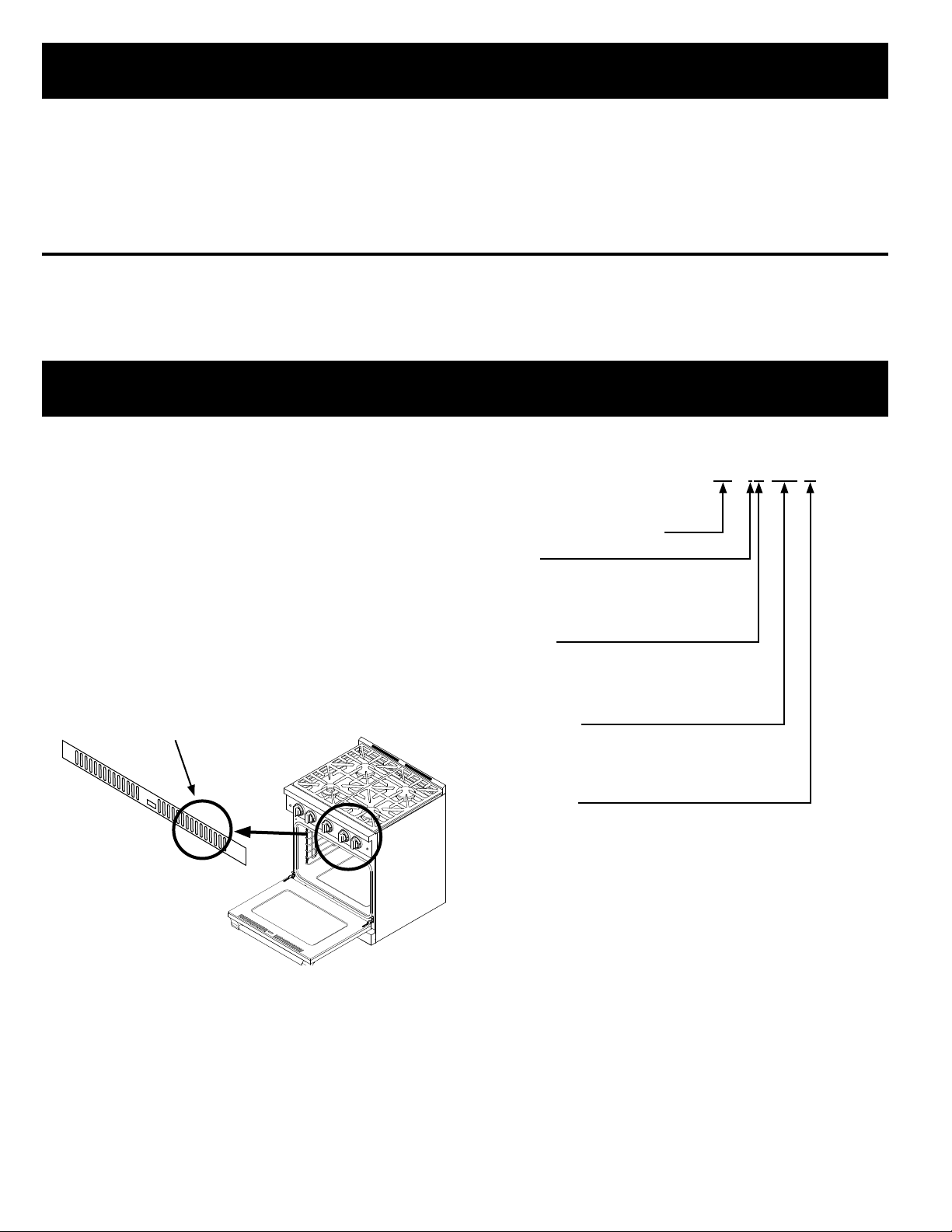
Table of Contents
Important Safety Instructions .....................................................1
Planning the Installation .............................................................. 3
Electrical Requirements .............................................................. 3
Gas Supply Requirements .......................................................... 3
Product Dimensions .................................................................... 4
Cabinet Layout ............................................................................ 5
Installation Instructions ............................................................... 7
Preparing for Installation ............................................................. 7
IMPORTANT:
• Installer: In the interest of safety and to minimize problems, read these installation instructions completely and carefully before you
begin the installation process. Leave these installation instructions with the customer.
• Customer: Keep these installation instructions for future reference and the local building inspector’s use.
Gas Connection ........................................................................ 10
Final Installation ........................................................................ 11
Installing the Burner Knobs ......................................................12
Cooktop Assembly .................................................................... 13
Verifying Proper Operation .......................................................14
Removing the Range for Service..............................................14
Reinstalling the Range After Service ........................................14
Installation Checklist ................................................................. 14
Customer Service Information
If you have questions or problems with installation, contact your
Dacor dealer or the Dacor Customer Service Team. For repairs
to Dacor appliances under warranty call the Dacor Distinctive
Service line. Whenever you call, have the model and serial
number of the appliance ready. The model and serial number
label is located inside the grate, inside the door.
Dacor Customer Service Team
Phone: (800) 793-0093 ex. 2813 (U.S.A. and Canada)
Monday — Friday 6:00
Web site: www.dacor.com
Dacor Distinctive Service (for repairs under warranty only)
Phone: (800) 793-0093 ex. 2822 (U.S.A. and Canada)
Monday — Friday 6:00
Model and serial
number label located
inside grill
a.m. to 5:00 p.m. Pacific Time
a.m. to 5:00 p.m. Pacific Time
Model Identification
RNRP30G S/NG/H
SIZE (width in inches)
TRIM
I = Island
No Character = Freestanding
COLOR
C = Custom color
S = Stainless steel
GAS TYPE
NG = Natural Gas
LP = Liquid Petroleum (Propane)
Model and Serial Number Location
All specifications subject to change without notice.
No liability is assumed by Dacor
© 2015 Dacor, all rights reserved.
ALTITUDE
H = Equipped for high altitude operation,
4000 ft. (1219 m) and up
No Character = Equipped for low altitude operation
®
for changes to specifications.
Important Safety Instructions
Important Information About Safety
Instructions
The Important Safety Instructions and warnings in this manual
are not meant to cover all possible problems and conditions
that can occur. Use common sense and caution when installing,
maintaining or operating this or any other appliance.
Always contact the Dacor Customer Service Team about problems
and conditions that you do not understand.
Safety Symbols and Labels
DANGER
Immediate hazards that WILL result in severe personal injury or
death.
WARNING
Hazards or unsafe practices that COULD result in severe
personal injury or death.
CAUTION
Hazards or unsafe practices that COULD result in minor
personal injury or property damage.
WARNING
If the information in this manual is not
followed exactly, a fire or explosion may
result causing property damage, personal
injury or death.
- Do not store or use gasoline or other
flammable vapors and liquids in the
vicinity of this or any other appliance.
WARNING
WARNING – NEVER use this appliance as a space heater
to heat or warm the room. Doing so may result in carbon
monoxide poisoning and overheating of the appliance.
WARNING
NEVER cover any slots, holes or passages on the inside or
outside of the range or cover an entire rack with materials such
as aluminum foil. Doing so blocks air flow through the oven and
may cause carbon monoxide poisoning. Aluminum foil linings
may also trap heat, causing a fire hazard.
WARNING
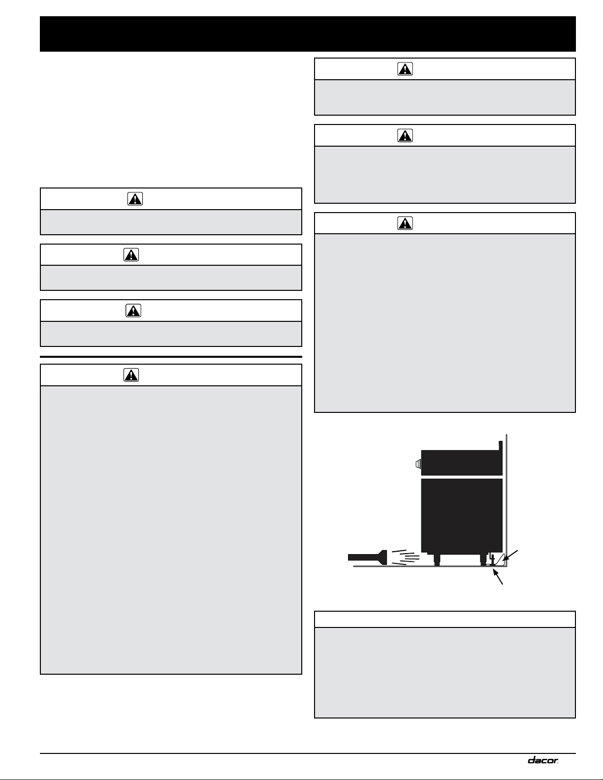
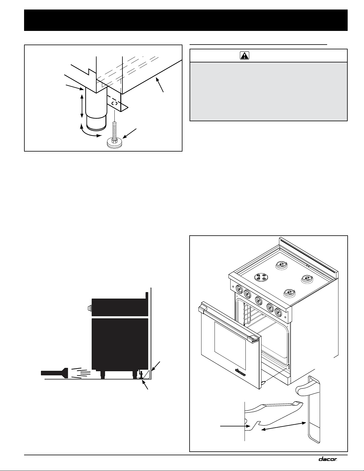
Tip-over hazard:
• A child or adult can tip the range and be killed.
• Attach the anti-tip bracket to the floor as directed in these
installation instructions.
• Engage the anti-tip bracket by sliding the anti-tip foot on
the range into it according to these installation instructions.
Using a flashlight, be sure that the anti-tip bracket engages
the range’s anti-tip foot as shown below.
• After moving the range, be sure to re-engage the anti-tip
foot into the anti-tip bracket as shown below.
• See the anti-tip bracket installation instructions in this guide
for further details.
• Failure to follow these instructions can result in death or
serious burns to children or adults.
- WHAT TO DO IF YOU SMELL GAS
• Do not try to light any appliance.
• Do not use any phone in your building.
• Immediately call your gas supplier from
a neighbor’s phone. Follow the gas
supplier’s instructions.
• If you cannot reach your gas supplier,
call the fire department.
- Installation and service must be
performed by a qualified installer, service
agency or the gas supplier.
READ AND SAVE THESE INSTRUCTIONS
Anti-tip
bracket
Anti-tip foot
CALIFORNIA PROPOSITION 65 WARNING
The burning of gas cooking fuel generates some by-products
that are on the list of substances which are known by the State
of California to cause cancer or reproductive harm. California
law requires businesses to warn customers of potential
exposure to such substances. To minimize exposure to these
substances, always operate this unit according to the use
and care manual, ensuring you provide good ventilation when
cooking with gas.
1
Important Safety Instructions
WARNING
• Read the accompanying use and care manual before
operating this appliance.
• Keep packaging materials away from children. Plastic
sheets and bags can cause suffocation.
• If you receive a damaged product, immediately contact
your dealer or builder. Do not install or use a damaged
appliance.
• This range must be properly installed and grounded by a
qualified installer according to these installation instructions
prior to use. The installer should show the customer the
location of the gas shut off valve and the electrical outlet
so that they know where and how to turn off the gas supply
and power to the range.
• This appliance should not be installed with a ventilation
system that blows air downward toward the range.
This type of ventilation system may cause ignition and
combustion problems with the gas cooking appliance,
resulting in personal injury or unintended operation.
• Do not use this appliance in combination with a surface
(countertop) ventilation system.
• This appliance is not designed for installation in a mobile
home or recreational vehicle.
• Do not install, repair or replace any part of the range unless
specifically recommended in the literature accompanying
it. A qualified service technician should perform all other
service.
• Do not connect this range to the gas supply without the
supplied gas pressure regulator installed.
• Before performing any type of service or installation, make
sure the gas supply and power to the range are turned off.
• NEVER block or cover any slots, holes or passages
anywhere inside the oven or on the outside of the range or
cover an oven rack with materials such as aluminum foil.
Doing so blocks airflow through the oven and cooktop and
may cause carbon monoxide poisoning or fire. See the
Getting to Know Your Range section of the use and care
manual for the location of the various air holes (slots).
• Only use the range for cooking tasks expected of a home
appliance as outlined in the literature accompanying it. This
range is not intended for commercial use.
• DO NOT TOUCH THE SURFACES OF THE OVEN[S] OR
COOKTOP DURING OR IMMEDIATELY AFTER USE.
• To avoid the possibility of fire, never leave this appliance
unattended when the cooktop is in use.
• Do not climb on any part of the appliance.
• Do not leave children or pets alone or unattended in the
area around the range. Do not allow children to play with
the controls, pull on the handle(s), or touch other parts of
the range.
• Do not store items of interest to children on top of or
above the range. Children could be burned or injured while
climbing on the appliance.
• Do not attempt to use this appliance in the event of a power
failure.
WARNING
• Clean the cooktop thoroughly before operating it for the first
time.
• Keep flammable items, such as paper, cardboard, plastic
and cloth away from the burners and other hot surfaces.
Do not place such items in the oven(s). Do not allow pot
holders to touch hot surfaces or gas burners.
• Do not wear loose or hanging apparel while using the
range. Do not allow clothing to come into contact with the
interior of the oven(s) or the cooktop and surrounding areas
during and immediately after use.
• To avoid a fire hazard, do not hang flammable or heat
sensitive objects over the range. If the range is near a
window, do not use long curtains as window treatment.
The curtains could blow over the cooktop and create a fire
hazard.
• Do not use the oven(s) for storage.
• Do not touch the outside surfaces of the range during the
self-clean cycle. They will be hot. Venting from the oven
may cause the cooktop and backguard to become hot.
• Make sure that all the cooktop parts are dry before lighting
a burner.
• Turn the knobs to the “OFF” position prior to removing them
from the valve stems.
• Do not operate the range without the backguard, the knobs
and trim rings in place.
• For your safety, do not use the oven to cook without the
convection filter(s) installed. When the filter is not installed,
the spinning fan blades at the back of the oven are
exposed.
• Do not line the oven(s) with aluminum foil or other
materials. These items can melt or burn up during selfcleaning and cause permanent damage to the appliance.
• Non-stick coatings, when heated, can be harmful to birds.
Remove birds to a separate, well-ventilated room during
cooking.
• IMPORTANT - This appliance is equipped with a threeprong grounding plug for your protection against possible
electric shock hazards. Plug it only into a dedicated,
grounded three-prong electrical outlet. It is the responsibility
of the customer to make sure the proper type of outlet is
installed. Under any circumstances:
◊ DO NOT cut or remove the third (ground) prong from the
power cord.
◊ DO NOT use an adapter plug.
◊ DO NOT use an extension cord.
◊ DO NOT use a power cord that is frayed or damaged.
◊ DO NOT connect to an electrical outlet with a ground
fault interrupter (GFI).
2
Planning the Installation
B
A
WARNING
• IMPORTANT: Observe all governing codes and ordinances
during planning and installation. Contact your local building
department for further information.
• To prevent an electric shock hazard, the power supply
must meet the specifications stated below. It is the owner’s
responsibility to make sure that the electrical service meets
electrical requirements and that the electrical outlet has
been properly installed by a licensed electrician.
The appliance installation must be electrically grounded in
accordance with local codes or, in the absence of local codes,
with the National Electrical Code, ANSI/ NFPA 70:
Electrical Requirements
• The range is supplied with a factory installed, 6 foot long,
power cord with a three-prong grounding plug. It is connected
to the chassis at the rear of the range. It must be connected
to a dedicated, grounded three-prong electrical outlet.
• The correct voltage, frequency, and amperage must be
supplied to the appliance from a separate, grounded, circuit
that is protected by a properly sized circuit breaker or timedelay fuse.
Circuit Required Total Connected Load*
120 Vac, 60 Hz, 15 Amp.
*These specifications for reference only. Refer to the rating label
for exact specifications (see below for location).
120 Vac 60 Hz, 5.0 Amp.
Gas Supply Requirements
• The installation of this appliance must conform with local
codes or, in the absence of local codes, with the National
Fuel Gas Code, ANSI Z223.1/NFPA 54.
• Be certain that the appliance being installed is correct for
the gas service provided (natural gas or LP gas). Also, if
operating the range at an altitude above 4000 ft. (1219 m)
make sure it is equipped for high altitude operation. Refer
to the range rating label and the table on the inside cover to
determine the correct model.
• See the table below for gas supply pressure requirements.
• The range comes from the factory with the regulator
installed. Use only the installed regulator. The regulator inlet
accommodates a 3/4” gas line. The range ships with a 1/2” to
3/4” adapter connected to the regulator.
GAS SUPPLY PRESSURE REQUIREMENTS*
Gas Type
Natural Gas
Liquid Propane
(LP)
* The gas supply pressure for testing the regulator setting shall
be at least 1 inch water column (249 Pa) above the specified
manifold pressure.
** Maximum gas supply pressure for all models: 1/2 psi.
The ratings above are for reference only. Refer to the rating label
for exact specifications (see below left for location).
GAS - ELECTRICAL ACCESS DIMENSIONS
A B
13 1/16” to 14 3/8”
(33.18 to 36.51 cm)
Minimum
Manifold Pressure
5-inch Water
Column
10-inch Water
Column
Minimum Gas
Supply Pressure**
6-inch Water
Column
11-inch Water
Column
4 5/16”
(10.95 cm)
Rating label is on top of
kickplate.
Open door and look
through gap to view label
information.
Rating Label Location
Gas and Power Access (Rear View)
Gas
Inlet
Power
cord
3

Planning the Installation
24” (61.0 cm)
Cabinet face
lines up with
back of control
panel
Stiffener
Cabinet face
Countertop
* Includes 3/16” (5 mm) space between downdraft cap and backsplash.
Back of
control
panel
ERV3015
downdraft
RNRP30G Range
3/8” min. (1.0 cm)
space behind
downdraft
chassis to clear
stiffener
3/8” min. (1.0 cm)
clearance required
between cap and
backsplash
30 1/2” (77.47 cm)*
Countertop height:
36 3/16" (91.9 cm) min.
37 1/2” (95.3 cm) max.
48” (121.9 cm)
Front of open door
Front of handle
Front edge of bull nose
Front panel
Rear of front panel/oven door
28 1/2” (72.4 cm)
(91.9 cm)
36 3/16”
(95.3 cm)
37 1/2”
26 7/8” (68.3 cm)
26” (66.0 cm)
24” (61.0 cm)
1 1/4”
(3.2 cm)
to
1 1/16” (2.7 cm) to
cooking surface
(top of grates)
Standard backguard is 3” high.
Optional 1.5” and 9” high
backguards are available.
3” (7.62 cm)
Product Dimensions
Product tolerances: ±1/16” (±1.6 mm)
Width: 29 7/8” (75.9 cm)
Range Dimensions (Side View)
Range Installed
(Side View)
4
Range Installed with Downdraft - Model ERV3015
Only (Side View)
Planning the Installation
Cabinet Layout
• All maximum and minimum dimensions and clearances
shown in the diagrams below must be maintained for safe
operation.
• Check the location where the range is to be installed. It
should be placed away from drafts that may be caused by
doors, windows and heating and air conditioning outlets.
• To reduce accumulated smoke in the room, Dacor strongly
recommends installation with a range hood or approved
downdraft.
• To reduce the risk of fire or personal injury from reaching over
a hot appliance, avoid cabinet installations directly above the
range. If cabinet storage is to be provided, the risk can be
reduced by installing a range hood that projects horizontally a
minimum of 5 inches beyond the bottom of the cabinets.
• The range may be installed flush to the rear wall. Dacor
strongly recommends installing a non-combustible material
on the rear wall above the range and up to the hood or
installation of a backguard. It is not necessary to install noncombustible materials behind the range below the countertop
height. Any openings in the wall behind the appliance or in
the floor underneath it must be sealed.
Gas and Electrical Service
• The shaded area shown below denotes the location of the
gas inlet and the electrical outlet. This is the recommended
location. For replacement purposes, the location of the
existing utilities may be utilized provided they do not interfere
with the sides or rear of the range. Check local building codes
for permissible gas valve locations.
• An external manual shut-off valve must be installed between
the gas inlet and the range for the purpose of turning on or
shutting off gas to the appliance.
The installation must allow for the following:
• Access to the gas shut-off valve when the unit is installed.
• Access to the electrical outlet, when the range is in place.
• The gas supply piping and shut-off valve, and the electrical
outlet must be located so they do not interfere with the range
when it is installed.
• The electrical outlet and gas shut off valve must be located
so that the range can be pulled out for service while the
appliance remains connected.
APPROVED DOWNDRAFT
Range Model RNRP30G
Downdraft ERV3015
Trim Kit
IMPORTANT: Read the ERV3015 Installation Instructions
for duct and electrical installation requirements. Use only
the Dacor downdraft model(s) specified above.
ATKERV-RP30 Trim Kit is required.
• A downdraft with a 3-inch backguard requires adding
the ATKERV-RP30 trim kit to create a uniform unit.
• Install ATKERV-RP30 onto the back of the range.
• The ATKERV-RV30 trim piece on the back of the range
will cover the downdraft chassis.
ATKERV-RP30 (Required when
using the 3-in backguard)
5

Planning the Installation
G
10" (25.4 cm) min.
to combustible side
walls above the range
(on both sides)
non-combustible
rear wall (recommended)
H
Backsplash
3/8" (1.0 cm)
min. for downdraft cap
clearance
J
Note 2
Note 2
F
G
2
Cabinet/countertop depth is at discretion of customer,
but cabinet face MUST NOT extend further than rear of
front panel, see product dimensions.
3
Consult the local code for exact location requirements.
1
Vertical from range grate level to combustible overhead
surface; if installing an overhead vent hood, also check
hood specifications for minimum required clearances.
4
Vertical from grate level to combustible surface.
Non-combustible
surface along back wall
recommended
10” (25.4 cm) min.
to combustible side
walls above the range
(both sides)
30” (76.2 cm)
min.
1
37 1/2”
(95.3 cm)
max.
13” (33.0 cm)
max.
5
15” (38.1 cm)
min.
4, 5
5
This specification does not apply for cabinets more
than a horizontal distance of 10” (25.4 cm) from the
edge of the range.
Suggested
location of
utilities
3
Grate
level
Cutouts & Tolerances
Cutout tolerances: +1/16” (+1.6 mm), -0 unless otherwise stated
H J
27 1/2” (69.9 cm) 3 1/2”
6
F G
36” (91.4 cm)*
30” (76.2 cm)**
* Recommended length
** Minimum length
30” (76.2 cm)**

Installation Instructions
Preparing for Installation
WARNING
• If the gas or electric service provided does not meet the
product specifications, do not proceed with the installation.
Call the dealer, the gas supplier or a licensed electrician.
• Before installing the range, you must locate and secure the
anti-tip bracket to the floor.
IMPORTANT: Within the Commonwealth of Massachusetts, this
appliance must be installed by a licensed plumber or gas fitter.
Unpacking the Range
Unpack the parts box and verify that all required components
have been provided. If any item is missing or damaged, please
contact your dealer immediately. Do not install a damaged or
incomplete appliance.
Parts List
- Grates (2)
- Standard burner caps
(3 brass, 3 porcelain)*
- Standard burner rings (3)
- SimmerSear burner caps
(1 brass, 1 porcelain)*
- SimmerSear burner ring (1)
- SimmerSear burner head (1)
- GlideRack™ oven racks (2)
- Standard rack (1)
- 5 Knobs (2 MAX GRIDDLE,
2 Standard, 1 Oven)
- Anti-tip bracket with screws
and anchors
- Griddle (1)
- Wok ring (1)
- Broiler pan/grill (1)
- Stainless steel cleaner (1)
- Literature kit (1)
Installing Rear Trim
If installing the range in the self-rimming configuration, or if the
range will be used with a downdraft, install the rear trim piece
first.
Remove the existing screws that hold the backguard in place and
use them to attach the trim piece. (See image below.)
Installing the Anti-Tip Bracket
Locate the anti-tip bracket included in the parts box.
There are two ways to install the anti-tip bracket:
• Floor mounting (preferred method).
• Wall mounting (alternate method). Use this method if floor
mounting is not suitable. If the front panel of the range
(excluding bull nose) is more than 27 inches (68.6 cm) from
the back wall, or if the flooring is too thick (see Installing
the Anti-Tip Bracket on the Wall), use the wall mounting
method.
*The range is supplied with two different styles of burner caps
(brass and porcelain) to suit the customer’s preference. Please
note that because the burner caps are made of brass, heat will
distort the brass’ color over time.
Replacing the Backguard
If a different backguard will be used, please assemble it before
pushing the range into position.
Model Number Item
APB30GLP 1.5-inch high Backguard (Low Profile)
APB30D9 9-inch high Backguard
Downdraft Installation
If installing a downdraft, install it before moving the range into
position.
An additional trim kit must be used to unify the downdraft, range,
and backguard into one piece.
Model Number Item
ERV3015 Downdraft
ATKERV-RP30 Trim Kit
Anti-tip
Bracket
Floor
surface
Sub-floor
Screws attached to
concrete sub-floor
(below floor surface).
Concrete anchors shown.
Do not use anchors on a wooden sub-floor.
Anti-Tip Bracket and Flooring Cross-Section
7

Installation Instructions
C
L
Installing the Anti-Tip Bracket to the Floor
WARNING
To perform its intended function, the anti-tip bracket must be
attached as instructed to the concrete slab or wood sub-floor
that is below any floor coverings (including cement board).
Do not attach the anti-tip bracket directly to floor coverings such
as ceramic/asphalt tile or linoleum.
Use the anchors and four (4) of the Phillips head screws when
attaching the anti-tip bracket to a concrete sub-floor.
• Four (4) plastic anchors
• 1-inch #8 (4)
• 1 1/4-inch #8 (4)
• 1 3/4-inch #12 (4)
Do not use these plastic anchors when attaching to a wooden
sub-floor.
Screws
Plastic Anchors
Bracket Install Detail
Mounting Holes
Installing the Anti-Tip Bracket to the Floor
1. Determine the location of the range center line and front
panel for the range’s final position based on the Product
Dimensions on page 5 and the actual cabinet / cutout
dimensions used for the installation.
2. Determine the placement of the anti-tip bracket, based on the
diagram below. Mark the four (4) mounting hole locations on
the floor with a pencil.
3. Determine the screw size required. The minimum full thread
depth (portion of screw threaded into wood/slab) for wood is
3/8” (1 cm) and 5/8” (1.6 cm) for concrete. See SCREW SIZE
TABLE to select the correct screw size.
Attaching the Bracket to a Concrete Floor:
• Drill four (4) 3/8” diameter countersink holes through any
existing floor covering down to the concrete slab below.
• Drill four (4) holes for the anchors 1 1/4” (3.2 cm) deep
into the concrete slab using a 3/16” masonry bit. This hole
length is longer than the anchor, but is required for proper
installation.
• Clear the holes of dust and any other material.
• Take a hammer and tap each anchor into the hole until the
anchor top is flush against the concrete slab.
• Place the anti-tip bracket on top of the anchors.
• Position the anti-tip bracket holes over the anchor holes,
and thread the screws into the anchors. Be sure the screw
threads fully engage the anchor body.
• Tighten the screws into place.
Attaching the Bracket to a Wood Floor:
If there is ceramic, asphalt, or another hard floor covering over
the wood, drill holes to allow access to the wood below for drilling
mounting holes.
Use the correct type of drill bit for the surface you will be drilling.
Once you have hit wooden flooring:
• Drill four (4) mounting holes into the wood using a drill bit
(1/16” dia. for #8 screws, 1/8” dia. for #12 screws).
• Position the anti-tip bracket holes over the holes in the floor.
• Insert the screws into the wood and tighten into place.
Bracket Placement
8
Range
center line
Range front
panel*
10 7/8”
A
22 1/2”
B

C
L
C
L
Installation Instructions
Installing the Anti-Tip Bracket to the Wall
1. Determine the suitability of wall mounting the anti-tip bracket.
To use the wall mount option, the range front panel (excluding
the bull nose) must not be more than 27 inches (68.6 cm)
from the wall, and the bracket screws must be able to thread
into the back wall’s interal base plate (see Inside the Back
Wall).
2. The notches on the sides of the bracket indicate the minimum
required height of the base plate and that any floor covering
is not too thick for proper screw thread engagement.
Determine if the Base Plate is High Enough:
The base plate is located on the floor, behind the wall. It will
anchor the anti-tip bracket (see Inside the Back Wall).
Find the range’s center line and front panel according to
the diagram below and the final installation cabinet / cutout
dimensions.
1. Find and mark the position of the anti-tip bracket, based on
the diagram below.
2. Push the bracket up against the wall and into position.
3. Determine if the base plate behind the wall (see Inside the
Back Wall) is tall enough to grab the screws.
• Using a pencil, mark a dot next to the notches on both sides
of the bracket. Drill just deep enough to see if the bit contacts
the base plate.
• When the drill bit contacts the base plate, you will know
screws in the anti-tip bracket will also contact the base plate.
This setup is successful.
• If the drill bit does not contact the base plate, the wall
mounting method should not be used. The floor mounting
method is more suitable, or the wall must be modified so that
the base plate can be accessed or anchors can be used.
Installing the Anti-Tip Bracket to the Wall
Drywall
Anti-tip
bracket
Inside the Back Wall (Side View)
SCREW SIZE TABLE
Sub-Floor Type/Floor
Covering Thickness
Concrete or wood sub-
floor, no floor covering
Concrete or wood sub-
floor, floor covering up to
1/4” thick
Concrete or wood subfloor, floor covering over
1/4” and up to 1/2” thick
Wood sub-floor, floor
covering over 1/2” and up
to 1 3/16” thick
Concrete under floor
covering over 1/2” thick
Wood sub-floor, floor
covering over 1 3/16” thick
* Included with range
** Determine required depth based on information in Step 3 and
purchase from local hardware store.
Notch
Wall
Base
plate
Screw Size
#8 x 1 *
#8 x 1 *
#8 x 1 1/4 *
#12 x 1 3/4 *
Must be purchased separately **
Must be purchased separately **
Range front panel
11 7/8”
Wall Mounted Anti-Tip Bracket (Top View)
9

Installation Instructions
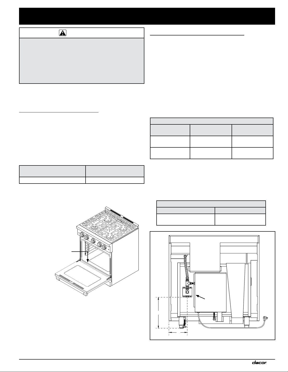
Removing the Oven Door
WARNING
• Do not attempt to disengage the hinge catches with the
door(s) removed from the range. The hinge springs could
release causing personal injury.
• Do not lift or carry the oven door(s) by the handle.
NOTE: When installing a backguard, always install it before sliding
the range into place. See page 7.
To make the range easier to move, remove the door(s) to reduce
weight.
1. Open the door until its lying completely open and flat.
2. Use a pair of needle nose pliers and a flat blade screwdriver
to rotate the catch over the retaining arm on each hinge (see
Oven Door Hinge)
Catch
Retaining Arm
Oven Door Hinge
3. Close the oven door three-quarters shut (see below).
4. Grasp each side of the door, just below the handle, with both
hands.
5. In a single motion, pull the door away from the oven while
continuing to lift up and out.
Connecting the Gas
WARNING
• Make sure the gas supply valve is off and that the power
cord to the range is disconnected prior to connecting the
gas line.
• Do not apply excessive pressure when tightening gas
connections and fittings.
• Do not use Teflon tape or plumber’s putty on gas flex line
connections.
• For LP installations, the LP gas tank must have its own
high pressure regulator. This is in addition to the pressure
regulator provided with the range.
• The maximum gas supply pressure to the regulator must
never exceed 1/2 pound per square inch (psi) or 3.5 kPa.
• The range and shut-off valve must be disconnected from the
gas supply piping during any pressure testing exceeding 1/2
psi (3.5 kPa).
• The range must be isolated from the gas supply piping by
closing the shut-off valve during any pressure testing at or
below 1/2 psi (3.5 kPa).
• Check all gas lines for leaks as instructed to avoid a fire or
explosion hazard. Do not use a flame to check for leaks.
NOTE: The gas pressure regulator is pre-set at the factory for the
type of gas intended for use with the appliance.
To verify that the appliance is compatible with the type of gas
available, check the range rating label (see inside cover for
location). Ranges intended for use with LP gas will have “LP” as a
part of the model number. Consult your dealer if the range is not
compatible with the type of gas being supplied.
Before Sliding the Range into Position:
1. Make sure the gas supply valve is OFF, and power to the
range is OFF.
2. Connect a flexible gas supply line to the gas shut-off valve.
This gas line needs to be long enough to allow the range
enough distance to be pulled out for service.
3. Slide the gas line up through the range’s access holes in the
back of chassis and up to the regulator. Move the wires tht
are inside the access holes to prevent them from catching on
the gas line as you maneuver the gas line.
4. Connect the gas line to the regulator.
5. Turn all cooktop control valves to OFF.
6. Turn the gas supply
ON.
7. Check all lines and
connections for
leaks using a soap
and water solution.
8. After verifying that
there are no gas
leaks, turn the
gas supply valve
connected to the
range to OFF.
Regulator
Door Closed Three-Quarters and Hand Placement
10
Flexible Gas Line
Installation Instructions
Finalizing the Anti-Tip Installation
Rear leg
Back of range
1 1/4” *
up
* Distance to floor:
4 1/16” to 5 5/16”
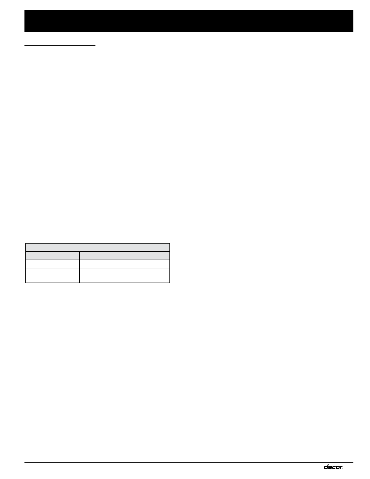
1. Peel the protective plastic coating off of the range, including
off of the door.
2. Adjust the leveling legs, as needed, to make sure the the trim
around the cooktop is flush with or above the countertop.
3. Locate the anti-tip foot on the back of the range. Lower (turn)
the foot until the range is 1/16” (2 mm) from the floor.
4. Carefully slide the range into position. The anti-tip foot should
seat within the anti-tip bracket.
• Confirm this by using a flashlight and looking underneath
the range. Make sure that the anti-tip foot is securely in the
middle of the bracket.
5. Use a level to confirm that the range is parallel to the ground
and stable. Re-adjust the legs and change the height if
necessary. Make sure the range does not tip or lean.
down
Anti-Tip Foot
(location varies)
Re-installing the Oven Door(s)
WARNING
To avoid personal injury or damage to the door from it falling off
its hinges:
• Make sure that the notch on the bottom of each oven door
hinge locks inside the receptacle before attempting to open
the oven door.
• Lock the hinges by rotating the top of the recepticale latch
toward the door. Do this immediately after the door is
installed.
The mating mechanism that holds the door in place is the door
hinge with a notch that locks into the oven receptacle. Make sure
the that the notches seat inside the receptacle.
1. Grasp each side of the oven door and hold it open 12 inches.
2. Slide the door hinges into the oven receptacles.
3. While pushing on the bottom corner of the door, insert the
hinge until the notch on the bottom of each hinge seats inside
the hinge receptacle.
4. Open the door so that it lays flat.
5. Lock both hinges by rotating the hinge tops toward the door.
Use a flathead screwdriver to do this.
6. Slowly and carefully open and close the door to ensure that it
is properly latched.
7. Remove any packaging from inside the oven(s).
Anti-tip
bracket
Anti-tip foot
Oven Hinge
Receptacle
Door Hinge
Notch on bottom
of hinge
Door Installation and Hinge Details
11

BROIL500 °400 °300 °200 °WARM CLEAN
Installation Instructions
Installing the Burner Knobs
WARNING
Installing the range knobs in the wrong position may result
in damage to the griddle included with the range. The knobs
for the center burners are marked with the maximum griddle
settings.
NOTE: There is a “D”-shaped key on the back of the knobs that
mate with a “D” on the valve stem. This key ensures that the knob
controls, icons, and valve stem align and work together.
There are three (3) different types of knobs supplied with the
range.
Knob Icons
Oven Broil
Right MAX GRIDDLE
Left Simmer
1. Put the Oven / Broil knob A on the oven valve stem.
2. Put the knobs with the “MAX GRIDDLE” on them B onto the
right burner valve stems. B
3. Put the remaining knobs C on the left valve stems.
C
C
A
B
B
Knob Placement
A
B
C
Oven / Broil Knob A
Max Griddle Burner Knob Icons B
Left Burner Knob Icons C
12

Installation Instructions
Assembling the Cooktop
WARNING
Never attempt to operate the range’s cooktop with any of the
burner rings, burner caps or grates removed.
Installing the Burners
There are two types of burners: the Simmer-Sear burner (left) and
the Standard burner (right). Refer to the illustrations and STEPS
below when intalling the burners and grates.
• Either type (color) of the burner caps may be used.
• When installing the burner components, twist each piece
back and forth slightly until it drops securely into place.
• The burners will not operate properly unless all of the burner
pieces are properly seated.
• Gently set the grates on top of the spill tray, and fit the legs of
each grate into its corresponding notch.
SimmerSear™
burner
Spill tray
Standard
burner
STEP 3:
Place burner cap on top
of burner ring.
• Flat surface is
pointing upward.
STEP 2:
Install burner ring.
• Line up ring
tabs with head
slots.
STEP 1:
Install burner
head.
• Put burner
head tab in
keyed hole.
Burner cap
Burner ring
Burner head
STEP 3:
Place burner caps on top
of rings.
• Flat surface is
pointing upward.
STEP 2:
Turn burner ring until it
drops into place.
Burner
ring
STEP 1:
Put burner ring on
top of head.
Keyed
hole
Burner base
SimmerSear™ Burner Installation
Burner
head
Standard Burner Installation
13

Installation Instructions
Verifying the Correct Setup
Before using the range, read the accompanying Use and Care
Manual completely. It contains Important safety, service, and
warranty information.
1. Before beginning this test procedure, ensure that all cooktop
control valves are OFF, and all burner rings, burner caps, and
grates are properly placed on the cooktop.
2. Turn the gas supply ON at the shut-off valve.
3. Plug the power cord into an electrical outlet. When the range
is first connected, the oven indicator light flashes for about 10
seconds while the range’s circuitry begins.
4. Wait for the light to stop flashing before going to Step 5.
IGNITION TEST:
5. Test a burner by pushing the knob and turning it to HIGH.
• It may take up to FOUR seconds for ignition, at which time
the ignitor will stop sparking. If ignition does not occur within
FOUR seconds:
• turn the knob to OFF, wait for at least five minutes to
allow any gas to dissipate, then repeat the ignition test.
6. After ignition, rotate the control
knob from HIGH to LOW to adjust
the flame.
When the range is correctly
installed, the flame will be steady
and quiet. It will also have a
sharp, blue inner cone that will
vary in length proportional to
the burner size. Dacor’s Smart
Flame™ feature reduces the
flame under the grate to increase
the life of the grate. If the range is equipped for
use with LP gas, the ends of the flame may be
yellow, which is normal.
7. Turn the control knob to OFF.
8. Repeat the ignition test for all the remaining
burners. After testing, turn them off.
9. Open the oven door(s). Test the oven light(s) by turning the
light switch(s) on the control panel.
10. Turn on the convection fan switch(s). You should hear the
convection fan, located behind the screen at the back of the
oven, come on.
11. With the oven door open, turn the oven temperature setting
to 400 °F. Both the knob and the oven ON indicator light next
to the knob should illuminate. Within 60 seconds, you should
hear the bake burner ignite below the oven floor. It should
begin to give off heat.
12. Turn the oven control knob to the BROIL position. The bake
burner should turn off. Both the oven control knob and the
oven ON indicator light should be illuminated.
13. Within 60 seconds the IR burner on the ceiling of the oven
should ignite and begin to give off heat.
14. Turn the oven knob to the OFF position.
Correct Flame
OFF Icon
If the range does not operate properly, follow these
troubleshooting steps:
1. Verify that power and gas are supplied to the range.
2. Check the electrical connections and gas supply to ensure
that the installation has been completed correctly.
3. Repeat the burner ignition test and/or oven test.
4. If the appliance still does not work, contact Dacor Distinctive
Service at (800) 793-0093 ex. 2822. Do not attempt to repair
the appliance yourself. Have the model and serial numbers
available when you call. See inside cover for location.
Dacor is not responsible for the cost of correcting problems
caused by a faulty installation.
Removing the Range for Service
1. Turn the gas supply valve to OFF.
2. Disconnect the power cord from the electrical outlet.
3. Pull the range out from the wall
Reinstalling the Range After Service
1. Push the range into operating position, making sure the antitip bracket is engaged (see page 11).
2. Connect the power cord to the electrical outlet.
3. Turn the gas supply valve ON.
14

Installation Instructions
Installation Checklist
WARNING
• To ensure a safe and proper installation, the following
checklist should be completed by the installer to ensure
that no part of the installation has been overlooked.
• Proper installation is the responsibility of the homeowner.
The importance of proper installation of your Dacor range
cannot be overemphasized.
□ Has the plastic coating been peeled off the outside of the
range? Have all packaging materials been removed from
inside the oven?
□ Are all leveling legs extended down to make contact with the
floor? Is the unit level? See page 11.
□ Is the range secured in place with the provided anti-tip
bracket and foot according to these instructions? See pages
7 and 11.
□ Has the gas supply inlet pressure been measured to ensure
that it does not exceed the maximums stated in these
instructions. See page 3.
□ Is the range connected to the gas supply according to these
instructions and in accordance with all applicable codes? Did
the installer check the gas supply for leaks?
□ Is the oven door properly installed according to these
instructions? See page 11.
□ Have the burner knobs been installed in the proper locations?
See page 12.
□ Are the burners assembled and grates properly installed
according to these instructions? See page 13.
□ Has proper operation been verified? Has the warranty
been activated on-line or the warranty card been filled out
completely and mailed?
15

Notes
16

Notes

Dacor ● 14425 Clark Avenue, City of Industry, CA 91745 ● Phone: (800) 793-0093 ● Fax: (626) 403-3130 ● www.dacor.com

ATKERV-RP30
Trim Kit for RNRP30G Range with
3-inch High Backguard + ERV Downdraft
Electric shock and explosion hazard! Before installation:
DANGER:
● turn the power OFF at the circuit breaker or fuse box, and
● turn the gas supply valve OFF.
Parts included with this kit:
Hardware Kit #
101307-21
WARNING: Do not maneuver or handle the range unless it is cool.
Trim Kit #
ATKERV-RP30
INSTALLATION
INSTRUCTIONS
• Make sure the downdraft is in place before sliding the range into position.
• Conrm that the range’s anti-tip bracket is re-engaged when the nal project is complete.
Instructions
STEP 1 Disconnect the range power supply at the
circuit breaker or fuse box. Turn the gas
OFF at the gas supply valve.
STEP 2 Remove the range grates.
STEP 3 Remove and discard the screws from the
rear of the backguard.
STEP 4 Position and hold the kit against the rear of
the backguard.
STEP 5 Thread the new screws through the kit and
into the backguard. Screw them rmly into
place.
STEP 6 Finish installing the downdraft and slide
the range into position.
STEP 7 Re-engage the range within the anti-tip
bracket.
Kit Installation on Backguard
backguard
range
RNRP30G Range
Shown
range
STEP 8 Connect the power to the circuit breaker
or fuse box.
STEP 9 Turn the gas supply valve ON.
Part No. 109308 Rev. A
 Loading...