

Page 1
Installation Instructions
Warming
Models:
Drawer
ERWD27, ERWD30, EWD24, EWD27, EWD30,
EWD36, IWD24, IWD27, IWD30, MRWD27,
MRWD30, MWDH27, MWDH30, MWDV27,
MWDV30, OWD24
Pa_ No. 102345 Rev. Q
Page 2

All specifications are subject to change without notice. Dacor ®assumes no liability for changes to specifications.
© 2007 Dacor, all rights reserved.
Page 3
Before You Begin .............................................................. 1
Important Safety Instructions .......................................... 1
General Safety Precautions ............................................. 2
Installation Specifications ................................................ 3
Verifying the Package Contents ....................................... 3
Installation Planning ......................................................... 3
Install Support Platform in Cabinet .................................. 6
Electrical and Environmental Specifications .................... 6
Installation instructions .................................................... 7
Remove the Drawer ........................................................ 7
Installing the Chassis ....................................................... 7
Re-installing the Drawer ................................................... 8
Towel Rack Installation ................................................... 8
Verify Warming Drawer Operation ................................... 9
Installation Checklist ........................................................ 9
Important:
InstalJer: In the interest of safety and to minimize problems, read these installation instructions completely and carefully
before you begin the installation process. Leave these installation instructions with the customer.
Customer: Keep these installation instructions for future reference and the local electrical inspector's use.
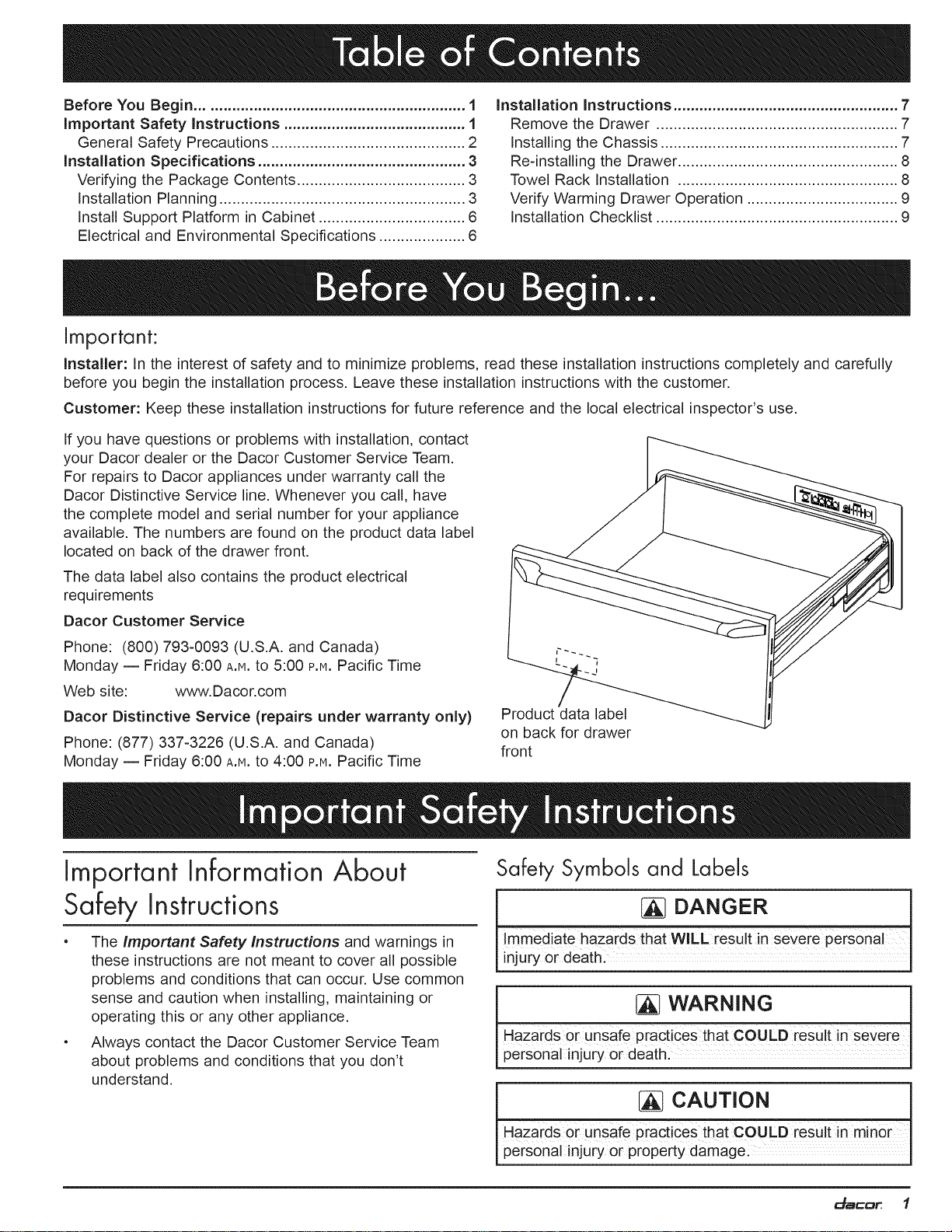
If you have questions or problems with installation, contact
your Dacor dealer or the Dacor Customer Service Team,
For repairs to Dacor appliances under warranty call the
Dacor Distinctive Service line, Whenever you call, have
the complete model and serial number for your appliance
available, The numbers are found on the product data label
located on back of the drawer front,
The data label also contains the product electrical
requirements
Dacor Customer Service
Phone: (800) 793-0093 (U.S.A. and Canada)
Monday -- Friday 6:00 A.H. to 5:00 P.M.Pacific Time
Web site: www.Dacor.com
Dacor Distinctive Service (repairs under warranty only)
Phone: (877) 337-3226 (U.S.A. and Canada)
Monday -- Friday 6:00 A.H. to 4:00 p.m.Pacific Time
Important Information About
Safety Instructions
The important Safety instructions and warnings in
these instructions are not meant to cover all possible
problems and conditions that can occur. Use common
sense and caution when installing, maintaining or
operating this or any other appliance.
• Always contact the Dacor Customer Service Team
about problems and conditions that you don't
understand,
Product data label
on back for drawer
front
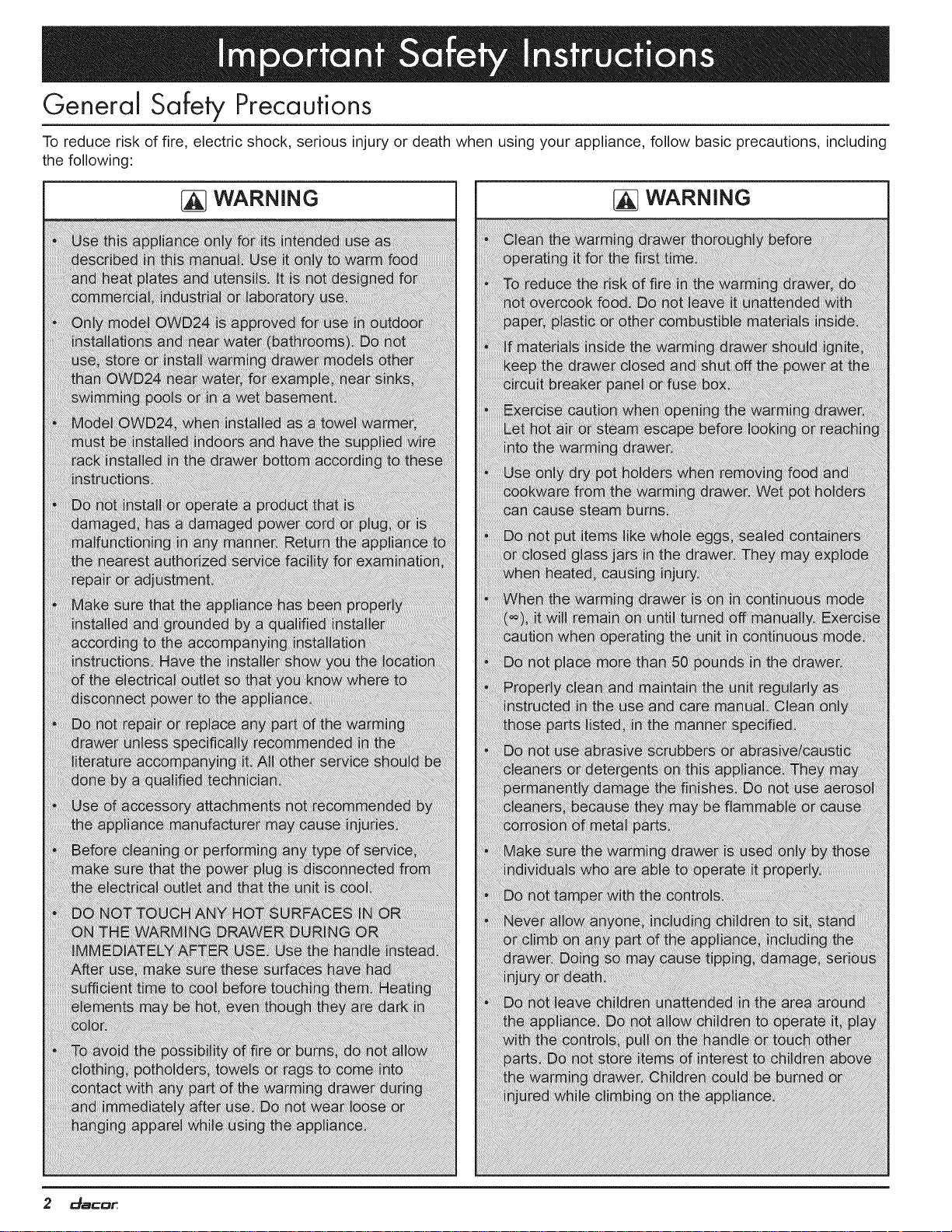
Safety Symbols and Labels
DANGER
Immediate hazards that WILL result in severe PerSonal
njury 0r death:
WARNING
HaZards 0i unsafe practices that COULD result in Severe
personal injury or death.
CAUTION j
HaZards 0i uasafe practices that COULD res u t nor
personal injury or property damage_ J
_a_D_ f
Page 4
General Safety Precautions
To reduce rJsk of fire, electrJc shock, serJous Jnjury or death when usJng your applJance, follow basJc precautions, JncludJng
the followJng:
_] WARNING WARNING
2 _SCD_
Page 5

Verifying the Package Contents c
• (3) mounting screws - PN 83569
• Wire rack with mounting hardware (OWD24 only)
(1) PN 83619 (screw), (1) PN 83267 (clamp)
B
\
Installation Planning
• A qualified technician must complete the installation of this built-
in appliance. Proper installation is the customer's responsibility.
Carefully check the location where the drawer is to be installed.
The drawer should be placed for convenient access. Make
certain that electrical power can be provided in the selected
location. Install the warming drawer in wood cabinets only.
• Plan the installation so that all minimum clearances are met or
exceeded. Dimensions shown provide minimum clearances,
unless otherwise noted. Be certain that proper clearance is
provided for the drawer door when it is in the open position.
• The specified minimum cabinet depth and width must be
provided. The cabinet depth and width must completely enclose
the recessed portion of the drawer.
Cabinet cutout dimensions must be used as indicated. All
contact surfaces between the appliance and the cabinet must
be solid and level. The drawer support platform must be flush
with the bottom edge of the cabinet cutout.
• Make certain that you have everything necessary to ensure a
proper installation before proceeding.
• A custom front panel is required for IWD
series models and optional for OWD24.
• An optional Epicure ®style front panel kit
is available for model OWD24.
Chassis
Drawer open
Overall Dimensions - IWD/OWD Series
Top View
Mounting hole,
9 places 3 prong
40" (101.6 cm)
120 Vac power cord
I
I
I
ol
o
5/16"
(8 ram)
f
Model
IWD24
IWD27
IWD30
OWD24
Drawer Face Dimensions
(IWD/OWD Series)
(A) Dimension
Drawer Face
Width
22 5/16" (56.7 cm)
25 5/16" (64.3 cm)
28 5/16" (71.9 cm)
22 1/2" (57.1 cm)
(B) Dimension
Chassis Width
22 1/4" (56.5 cm)
25 1/4" (64.1 cm)
28 1/4" (71.8 cm)
22 1/2" (57.1 cm)
(C) Dimension
Chassis Face
Width
22 3/8" (56.8 cm)
25 3/8" (64.5 cm)
28 3/8" (72.1 cm)
22 1/2" (57.1 cm)
See following page for chassis dimensions for other models
Chassis without
drawer installed
** = OWD24 mounting holes
Chassis Dimensions
(IWD/OWD Series)
(D)
Dimension
Drawer
Face Height
8 15/16"
(22.7 cm)
11 7/8" 20" 18" 11 7/8"
(30.2 cm) (50.8 cm) (45.7 cm) (30.2 cm)
(E)
Dimension
Chassis
Depth
23 3/8"
(59.4 cm)
(F)
Dimension
Drawer
Depth
23 13/16"
(60.5 cm)
Dimension
Chassis
Height
9 1/16"
(23.0 cm)
da=Dr, 3
(G)
Page 6

Drawer Face Dimensions
(MWD series shown)
B =,-
"q C =_
\
Model
ERWD27
ERWD30
EWD24
EWD27
EWD30
EWD36
MRWD27
MRWD30
MWDH27
MWDH30
MWDV27
MWDV30
(A) Drawer Face
Width
27" (68.6 cm)
30" (76.2 cm)
24" (61.0 cm)
27" (68,6 cm)
30" (76,2 cm)
36" (91.4 cm)
26 3/4" (67,9 cm)
29 3/4" (75,6 cm)
27" (68,6 cm)
30" (76,2 cm)
27" (68,6 cm)
30" (76.2 cm)
(B) Chassis Face
Width
26 5/8" (67.6 cm)
29 5/8" (75.2 cm)
23 5/8" (60.0 cm)
26 5/8" (67.6 cm)
29 5/8" (75.2 cm)
35 5/8" (90.5 cm)
26 5/8" (67.6 cm)
29 5/8" (75.2 cm)
26 5/8" (67.6 cm)
29 5/8" (75.2 cm)
26 5/8" (67.6 cm)
29 5/8" (75.2 cm)
(C) Chassis Width
25 1/4" (64.1 cm)
28 1/4" (71.8 cm)
22 1/4" (56.5 cm)
25 1/4" (64.1 cm)
28 1/4" (71.8 cm)
34 1/4" (87.0 cm)
25 1/4" (64.1 cm)
28 1/4" (71.8 cm)
25 1/4" (64.1 cm)
28 1/4" (71.8 cm)
25 1/4" (64.1 cm)
28 1/4" (71.8 cm)
Warming Drawer Overall Dimensions
See page 3 for IWD and OWD series chassis dimensions
ERWD EWD
3 1/2" 1 I-- 3 7/16' 1
Chassis
Drawer open
Overall Dimensions
Top View
(EWD series shown)
23 3/8"
(59.4 cm)
A '
5/64"
_)mm)
23 13/16"
(60.5 cm)
10"
(25.4 cm)
(,9 cm) (87cm),,
1 1/8'_D_ 1 _10 _"
(2.9 cm) //I...... (2.5 cm) l I
MRWD30B
(only)
All other MRWD MWDH/V
series (31/4"m_ I
cm) i iv -_,
Handle Dimensions
Mounting 3-prong 120 Vac
hole 9 places power cord
40" (101.6 cm)
\
4 _SCD_
1/2" (1.3 cm)
Chassis Dimensions
Page 7

36" typ.
(91.4 cm)
36" typ.
(91"l cm)
®®
®
• Warming
drawer
Warming
drawer
120 Vac
electrical
outlet
9
®
I o®
!
B
1 1/2" (3.8 cm)
Cooktop..._ f Typical countertop
®
O
Warming
drawer
®
O
O
_- 3/4" min.*
!
120 Vac
electrical
outlet
C (1.9 cm)
c
. cm)
single wall oven
l 27"/30"/36" Dacor 1
i Warming 120 Vac_
drawer elect. !1_
i Warming 120 Vac_
drawer elect. I_ j
Toe kick
A _1
Cutouts Dimensions
NOTES:
Models EWD36 and OWD24 cannot
be installed above or below another
warming drawer (any type).
Model OWD24 is not approved for
installation above, below or adjacent
to a wall oven or a warming drawer,
including the same model.
D
C
D
C
3/4" min.*
(1.9 cm)
Model
ERWD27
ERWD30
EWD24
EWD27
EWD30
EWD36
IWD24
IWD27
IWD30
MRWD27
MRWD30
MWDH27
MWDH30
MWDV27
MWDV30
OWD24
(B) Min. Width to
(A) Cutout Width
Adjacent Doors/
(C) Cutout Height
Drawers
25 1/2" (64.8 cm)
28 1/2" (72.4 cm)
22 1/2" (57.2 cm)
25 1/2" (64.8 cm)
28 1/2" (72.4 cm)
34 1/2" (87.6 cm)
22 1/2" (57.2 cm)
25 1/2" (64.8 cm)
28 1/2" (72.4 cm)
25 1/2" (64.8 cm)
28 1/2" (72.4 cm)
25 1/2" (64.8 cm)
28 1/2" (72.4 cm)
25 1/2" (64.8 cm)
28
1/2" (72.4 cm) 30 1/4" (76.8 cm)* 9 1/8" (23.2 cm) 1 1/4" (3.2 cm)*
22
5/8" (57.5 cm) 24 1/4" (61.6 cm)*** 11 15/16" (30.3 cm) NA
27 1/4" (69.2 cm)*
30 1/4" (76.8 cm)*
24 1/4" (61.6 cm)*
27 1/4" (69.2 cm)*
30 1/4" (76.8 cm)*
36 1/4" (92.1 cm)*
27" (68.6 cm)*
30" (76.2 cm)*
27 1/4" (69.2 cm)* 9
30 1/4" (76.8 cm)* 9
27 1/4" (69.2 cm)* 9
9 1/8" (23.2 cm)
9 1/8" (23.2 cm)
9 1/8" (23.2 cm)
9 1/8" (23.2 cm)
9 1/8" (23.2 cm)
9 1/8" (23.2 cm)
9 1/8" (23.2 cm)
9 1/8" (23.2 cm)
9 1/8" (23.2 cm)
9 1/8" (23.2 cm)
9 1/8" (23.2 cm)
1/8" (23.2 cm)
1/8" (23.2 cm)
1/8" (23.2 cm)
(D) Min. Vertical Gap
Between Cutouts
1 1/4" (3.2 cm)*
1 1/4" (3.2 cm)*
1 1/4" (3.2 cm)*
1 1/4" (3.2 cm)*
1 1/4" (3.2 cm)*
1 1/16" (2.7 cm)
1 1/16" (2.7 cm)
1 1/16" (2.7 cm)
1 1/4" (3.2 cm)*
1 1/4" (3.2 cm)*
1 1/4" (3.2 cm)*
1 1/4" (3.2 cm)*
1 1/4" (3.2 cm)*
NA
Min. Cutout
Depth
24" (61.0 cm)
20 1/8" (51.1 cm)
* Bare minimum spacing to allow for ventilation and avoid scraping on ERW, EWD, MRW and MWD series models.
** IWD models or OWD24 without the optional front panel kit: The chassis and drawer faceplate are smaller than the
cutout. The custom front panel mounts to the drawer faceplate. The height and width of the custom front panel must
exceed the cutout dimensions (A and C above) to cover the hole. Allow 1/4" minimum additional space on the top, bottom
and sides from the custom front panel edge to prevent scraping against adjacent doors, drawers and the countertop.
*** OWD24 with optional factory front panel kit only. Bare minimum spacing shown to avoid scraping. Gap above and
below cutout is 3/4" minimum. See ** above for OWD24 with custom front panel.
_a_D_ 5
Page 8

Install Support Platform in
Cabinet
Provide a platform (100 lb. load capacity) within the cabinet
upon which the warming drawer will be supported. The
platform must be installed level and straight. The top edge
of the platform must be flush with the cutout at the front of
the cabinet. There are no provisions to level the warming
drawer after it has been installed. 3/4" (1.9 cm) thick
plywood is recommended.
NOTE: If the drawer is not installed in a level fashion, the
drawer may slide open on its own or may not seal tightly,
allowing heat to escape and resulting in poor warming
drawer performance.
Electrical and
Environmental
Specifications
WARNING
IMPORTANT: This appliance is equipped with a three
prong grounding electric plug for protection against
possible electric shock hazards. It must be plugged into
a dedicated, grounded, electrical outlet. If only a two
prong electrical outlet is available, it is the responsibility
of the customer to have it replaced with a dedicated,
properly grounded three prong electrical outlet. To
avoid an electric shock hazard, do not under any
circumstances:
__ R__
I
a
a
a
a
I
I
a
Ii
Minimum ambient operating temperature: 32°F (0°C).
Ii
The correct voltage, frequency and amperage must be
face
a
a
I
I
a
a
a
a
supplied to the electrical outlet from a grounded, single
phase circuit that is protected by a properly sized circuit
breaker or time-delay fuse.
The required voltage, frequency and amperage ratings
are listed on the product data label. See page 1 for
location.
Nominal Electrical Supply Requirements
120 Vac, 60 Hz, 15 Amp., dedicated circuit
The warming drawer is supplied with a 40" (101.6 cm)
power cord with a three prong grounded plug.
Total Connected Load 0.5 kW (4Amp.)
o Cut or remove the third (ground) prong from the power
cord.
• Use an adapter plug.
o Use a power cord that is frayed or damaged.
• Immerse the power cord or plug in water or other
liquid.
o Connect the appliance to an extension cord.
NOTE: Use of a ground fault interrupter (GFt) is not
recommended.
Three prong plug
Three prong
grounded outlet
The power supply requirements shown above are for
reference only. If they do not agree with those listed
on the product data label, use the requirements on the
product data label.
It is the owner's responsibility to ensure that the
electrical outlet is installed by a qualified electrician.
The electrical installation must comply with the latest
revision of the National Electric Code ANSI/NFPA 70
and local codes and ordinances.
• If the electrical service provided does not meet the
product specification, or does not conform to the NEC
or local standards, do not proceed with the installation.
Call a licensed electrician to correct the electrical
service before proceeding.
• Be certain to locate the electrical outlet in an
accessible location, so that the warming drawer may
be easily unplugged in the event that service becomes
necessary.
Keep the electrical cord away from hot surfaces.
6 _aCD_
Page 9

WARNING
To avoid personal injury caused by the appliance
falling forward when the drawer _sopened, secure
the chassis to the cabinet and support platform as
instructed.
Be certain that the power plug is disconnected from
the electrical outlet before installation.
• Verify that the electrical supply matches the ratings
found on the appliance data plate and the installation
specifications before proceeding.
Remove the Drawer
Remove the drawer from the appliance to allow access
to the mounting holes during installation, and to reduce
weight:
1. Pull the drawer out to the fully open position.
2. Push in on the locking tab on one side as you pull the
drawer up.
3. When the drawer comes loose from the slide, repeat
the same process on the opposite side.
4. Grip the drawer on both sides and pull it free.
5. For safety, push both drawer slides into the drawer
opening.
Installing the Chassis
1.
Grasp the warming drawer chassis on opposite
sides and slide it partially into the cabinet opening.
Temporarily support the chassis in place so that it will
not tilt or fall.
.
From an adjoining cabinet, reach in behind the drawer
and pull the power cord until the plug is next to the
electrical outlet. Do not plug in the power cord at this
time.
.
After positioning the power cord and plug, slide the
chassis completely into the cabinet until the front frame
is positioned flush against the cabinet face.
.
Use the screws provided to secure the warming drawer
chassis to the cabinet and support platform, insert them
into the mounting holes and tighten into place. You may
want to drill pilot holes prior to installing the mounting
screws.
Mounting hole, 9 places
STEP 2: Push
locking tab
STEP 3: Pull up on
front of drawer
Mounting Hole Locations =ERW, EWD, IWD, MRW and
MWD Series Models
(IWD series models do not have a flange around
the edge of the faceplate)
Mounting hole, 4 places
I
I
I
I
Mounting Hole Locations -
OWD24
Continued...
Style varies, EWD27 shown
_a_D_ 7
Page 10

Re-installing the Drawer Towel Rack Installation
.
Pull the drawer slides all the way out of the drawer
opening.
.
Gently lower the drawer between the extended slides
until it is suspended by them.
3. Slide the back of the drawer mounting brackets under
the drawer mounting clips on the slides.
4. Push one side of the drawer down onto its locking tab,
until the tab locks into place.
.
Repeat the same process on the opposite side.
6.
Gently open and close the drawer to make sure that it
(OWD24 Only)
Model OWD24 is designed so that it can be used as a
towel warmer if desired. Other models are not equipped for
this application. To use model OWD24 as a towel warmer,
you must install the towel rack included with the unit in the
bottom of the drawer.
To install the towel rack:
1. Open the drawer completely.
2. Insert the towel rack into the drawer in the orientation
shown below,
is properly installed.
STEP 3: Slide mounting
bracket under clip on slide
\
STEP 4: Push front
of drawer down until
tabs lock into place
Slide
Clip on slide
.
Use the clamp and screw included with the rack to
attach it to the back of the drawer face as shown
below. There is a hole for the screw in the back of the
face plate near the bottom.
8 _SCD_
Page 11

Warming Drawer Control Panel Layout
Verify Warming
Drawer
Operation
1. Connect power plug to the electrical outlet.
2. Open the drawer and press the ON/OFF key on the
control panel,
,
Press the PROOF, LOW, MED and HIGH keys each
in turn. When you press each key, the indicator directly
above it should light. Leave the control panel set to
HIGH.
4. Press the SELECT key. The 1 HOUR indicator should
light. Press and release the SELECT key three (3)
more times. Each time you press the SELECT key, the
2 HOUR, 3 HOUR and 4 HOUR indicator lights should []
come on. All lights should be on after pressing the
SELECT key the third time.
5. Press the "oo" key. The indicator light above it []
should come on and the 1, 2, 3 and 4 HOUR
lights should go out.
6. The warming drawer should begin to heat.
You should begin to feel the inside of the []
drawer begin to heat within five (5) to ten (10)
minutes.
7. When you have determined that the heating
element is working, press the ON/OFF key.
If the warming drawer does not operate properly, follow
these troubleshooting steps:
• Verify that the circuit breaker for the electrical outlet
is on and not tripped. Make sure the power plug is
connected.
Installation Checklist
WARNING
- To ensure a safe and proper installation, the following
checklist should be completed by the installer to
ensure that no part of the installation has been
overlooked.
- Proper installation is the responsibility of the
homeowner. The importance of proper installation of
your warming drawer cannot be overemphasized.
[]
Support platform has been installed according to the
instructions on page 6.
Properly grounded, dedicated, three prong electrical
outlet has been installed for the appliance by a licensed
electrician. See page 6.
The chassis has been properly fastened to the support
platform and sides of the cabinet.
See page 7.
The drawer has been properly installed. See page
8.
[] Model OWD24 for use as towel warmer: The towel rack
has been installed. See page 8.
[] Proper operation has been verified?
[] The warranty has been activated on-line or the
warranty card filled out completely and mailed?
[] Save these instructions for future reference.
• Repeat the above tests.
• If the appliance still does not work, contact Dacor
Distinctive Service at (877) 337-3226. Do not attempt
to repair the appliance yourself. Be sure to have the
model and serial numbers available when you call. See
page 1 for model/serial number location.
Dacor is not responsible for the cost of correcting problems
resulting from a faulty installation.
_a_D_ 9
Page 12

The Life of the Kitchen?
Dacor • 600 Anton Blvd. Suite 1000 Costa Mesa, CA 92626 • Phone: (800) 793-0093 • Fax: (626)403-3130 • www.Dacor.com
® . Family Owned
American Maae
 Loading...