

Page 1
ERV3015, ERV3615, ERV36-ER, ERV48, ERV48-ER,
Document # PG08-001
PRV30, PRV36, PRV48
Renaissance
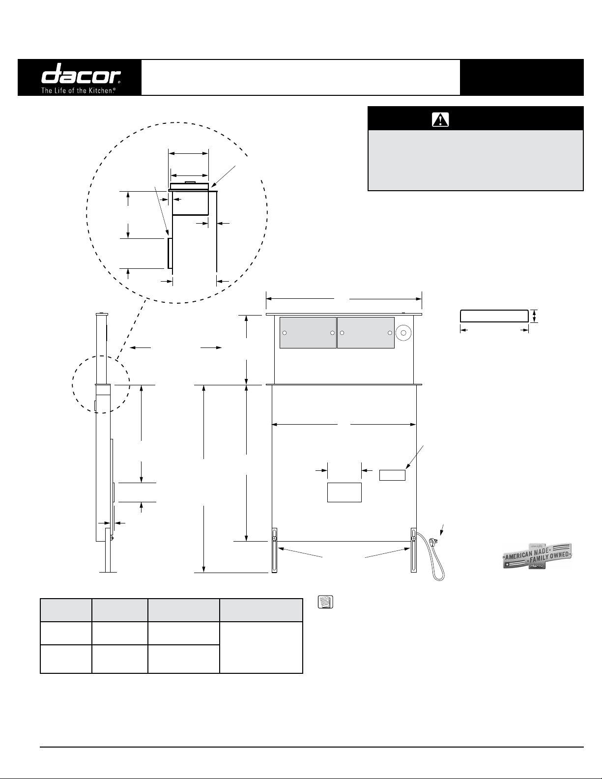
DIMENSIONS - MODELS ERV3015, ERV3615
2 3/16”
(5.6 cm)
”
5/16” (8 mm)
thick stiffener
across back
3”
(7.6 cm)
”
1 15/16
(4.9 cm)
2 1/8
(5.4 cm)
3/16”
(5 mm)
2 9/16”
(6.5 cm)
Vent shown
in raised
position
®
Downdraft Vents
Top cap with
vent down
9/16”
(1.4 cm)
* Total chassis depth with
optional CABP3 blower
installed is 10 3/8” (26.3 cm).
*
15"
(38.1 cm)
Slim Chassis
• Observe all governing codes and ordinances
during planning and installation. Contact your
local building department for further information.
• This appliance must be installed in accordance
with the accompanying installation instructions.
All tolerances: ±1/16” (±1.6 mm)
unless otherwise stated
A
Revised 02/28/14 Page 1/7
PLANNING
GUIDE
WARNING
2 1/8” (5.4 cm)
Top cap - side view
3/8”
(1.0 cm)
20”
(50.8 cm)
3 3/4”
(9.5 cm)
1 1/8”
(2.9 cm)
SIDE VIEW
Model No. A B
ERV3015
ERV3615
** Includes power supply requirements for blower
30”
(76.2 cm)
36”
(91.4 cm)
30 1/4”
(76.8 cm)
to
37 1/4”
(94.6 cm)
27 3/8”
(69.5 cm)
33 3/8"
84.8 cm)
30"
(76.2 cm)
Circuit
Requirement**
Three prong electri-
cal outlet connected
to 120 Vac, 60 Hz.,
15 Amp. grounded,
dedicated, circuit
B
6”
(15.2 cm)
Motor
cover
Front of unit
Adjustable
anchor legs
FRONT VIEW
NOTES:
1. Maximum installed height must not exceed the maximum
specified countertop height of cooking appliance.
2. Install these downdraft vents only with approved Dacor
appliances. See the planning guide for the particular
appliance for proper applications and cutout information.
3. This appliance must be install in conjunction with
a single, Dacor approved blower. See page 4/7 for
approved blowers.
4. Local building codes may require the use of makeup
air systems. Consult a qualified HVAC specialist when
designing the system for the requirements in your area
and to assure optimal performance.
Product
data label
28" 3 prong
grounded
power cord
All specications subject to change without notice.
Phone: (800) 793-0093www.dacor.com
Page 2
ERV3015, ERV3615, ERV36-ER, ERV48, ERV48-ER,
Document # PG08-001
PRV30, PRV36, PRV48
Renaissance Slim Chassis
Downdraft Vents
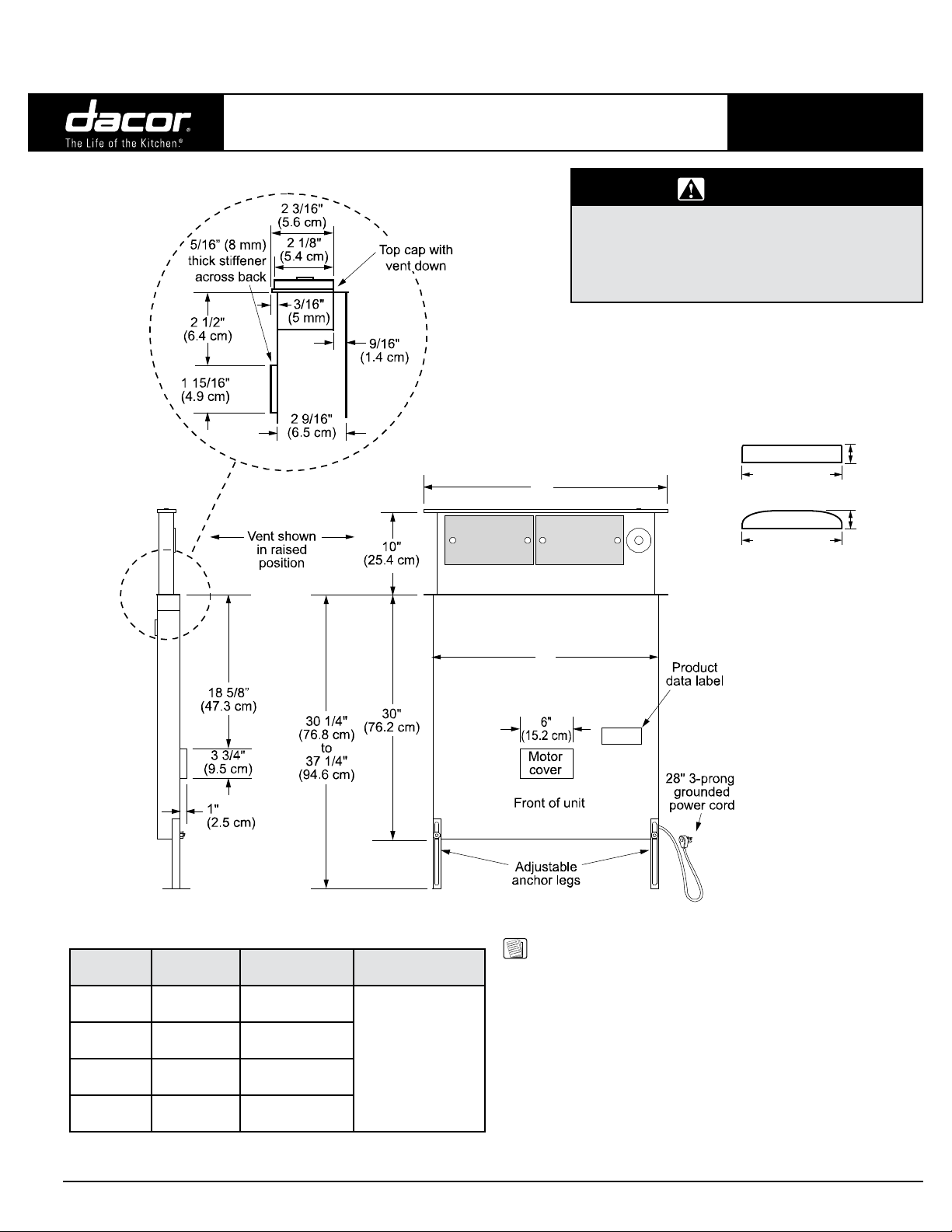
DIMENSIONS - MODELS ERV48, PRV30, PRV36, PRV48
Revised 02/28/14 Page 2/7
PLANNING
GUIDE
WARNING
• Observe all governing codes and ordinances
during planning and installation. Contact your
local building department for further information.
• This appliance must be installed in accordance
with the accompanying installation instructions.
All tolerances: ±1/16” (±1.6 mm)
unless otherwise stated
A
2 1/8" (5.4 cm)
ERV top cap - side view
2 1/8" (5.4 cm)
PRV top cap - side view
3/8"
(1.0 cm)
7/16"
(1.1 cm)
SIDE VIEW
Model No. A B
PRV30
PRV36
PRV46
ERV48
** Includes power supply requirements for external blower
30”
(76.2 cm)
36”
(91.4 cm)
46”
(116.8 cm)
48”
(121.9 cm)
27 3/8”
(69.5 cm)
33 3/8”
84.8 cm)
43 3/8”
(110.2 cm)
43 3/8”
(110.2 cm)
Requirement**
Three prong electri-
cal outlet connected
to 120 Vac, 60 Hz,
15 Amp. grounded,
dedicated, circuit
Circuit
B
FRONT VIEW
NOTES:
1. Maximum installed height must not exceed the maximum
specified countertop height of cooking appliance.
2. Install these downdraft vents only with approved Dacor
appliances. See the planning guide for the particular
appliance for proper applications and cutout information.
3. This appliance must be install in conjunction with a
single Dacor approved blower. See page 4/7 for approved
blowers.
4. Local building codes may require the use of makeup
air systems. Consult a qualified HVAC specialist when
designing the system for the requirements in your area
and to assure optimal performance.
All specications subject to change without notice.
Phone: (800) 793-0093www.dacor.com
Page 3
ERV3015, ERV3615, ERV36-ER, ERV48, ERV48-ER,
Document # PG08-001
PRV30, PRV36, PRV48
Renaissance Slim Chassis
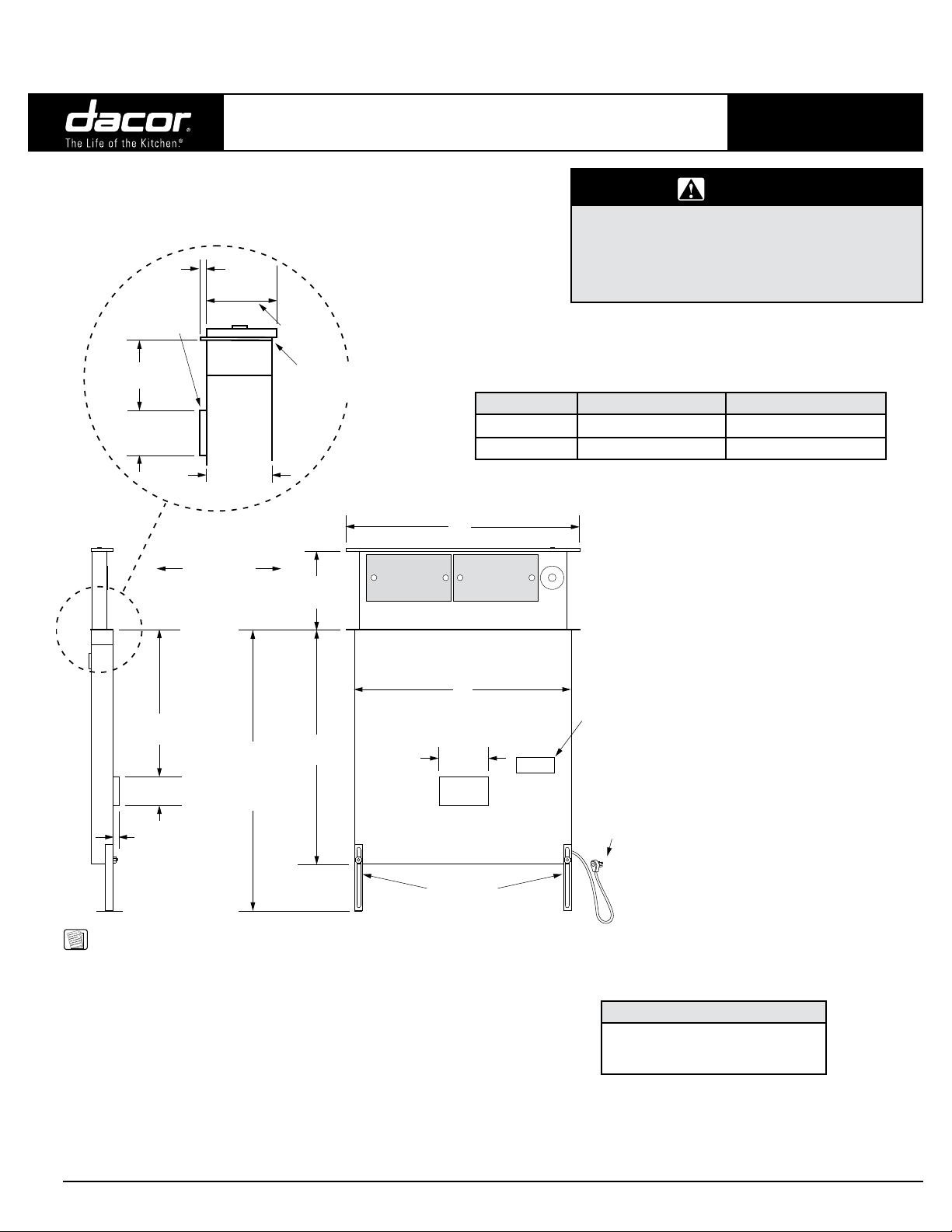
DIMENSIONS - MODELS ERV36-ER, ERV48-ER
1/4"
5/16” (8 mm)
thick stiffener
across back
2 1/2"
(6.4 cm)
1 15/16"
(4.9 cm)
(6 mm)
2 13/16"
(7.1 cm)
Top cap with
vent down
2 9/16"
(6.5 cm)
Downdraft Vents
All tolerances: +/- 1/16” (+/- 1.6 mm) unless otherwise stated
Model Number A B
ERV36-ER 36” (91.4 cm) 33 3/8” (84.8 cm)
ERV48-ER 48” (121.9 cm) 43 3/8” (110.2 cm)
NOTE: See the appliance planning guide page for cutout dimensions
A
Revised 02/28/14 Page 3/7
PLANNING
GUIDE
WARNING
• Observe all governing codes and ordinances
during planning and installation. Contact your
local building department for further information.
• This appliance must be installed in accordance
with the accompanying installation instructions.
Vent shown
in raised
position
10"
(25.4 cm)
B
18 5/8”
(47.3 cm)
3 3/4"
(9.5 cm)
1"
(2.5 cm)
30 ¼"
(76.8 cm)
to
37 ¼"
(94.6 cm)
30"
(76.2 cm)
6"
(15.2 cm)
Motor
cover
Front of unit
Adjustable
anchor legs
NOTES:
1. Maximum installed height must not exceed the maximum
specified countertop height of cooking appliance.
2. Install these downdraft vents only with approved Dacor
appliances. See the planning guide for the particular
appliance for proper applications and cutout information.
3. This appliance must be install in conjunction with a
single Dacor approved blower. See page 4/7 for approved
blowers.
4. Local building codes may require the use of makeup
air systems. Consult a qualified HVAC specialist when
designing the system for the requirements in your area
and to assure optimal performance.
Product
data label
28" 3 prong
grounded
power cord
Circuit Requirement (all models)*
Three prong electrical outlet con-
nected to 120 Vac, 60 Hz, 15 Amp.
grounded, dedicated, circuit
* Includes power supply requirements for
external blower.
All specications subject to change without notice.
Phone: (800) 793-0093www.dacor.com
Page 4

ERV3015, ERV3615, ERV36-ER, ERV48, ERV48-ER,
Document # PG08-001
PRV30, PRV36, PRV48
Renaissance Slim Chassis
Downdraft Vents
Duct System Layouts and Approved Blowers
IMPORTANT: Do not install more than one blower with this appliance.
APPROVED DACOR BLOWERS
Blower Model Blower Rating Compatible with
1
IMPORTANT: Due to a lack of clearance, do not use a CABP3 blower if a
range or wall oven is to be installed in front of the downdraft vent.
2
Nominal rating at zero inches static pressure, see the blower panning
guide page for actual blower ratings.
3
Revision B and later units only. Installation of blower model CABP3
requires Dacor adapter kit # AERVCAB.
■ The CABP3 blower assembly is mounted to the front of the downdraft
■ With ILHSF and REMP blowers, the downdraft vent can be configured
■ See the following pages for duct layout requirements and maximum
1
CABP3
ILHSF8 600 CFM
ILHSF10 1100 CFM
REMP3 600 CFM
REMP16 1000 CFM
vent with the exhaust pointing in the desired direction.
to exhaust through the back, the bottom or either side by removing
the appropriate exhaust knock-out.
duct length.
600 CFM
2
2
2
2
2
ERV30153, ERV3615
All Dacor ERV, PRV Series Models
All Dacor ERV, PRV Series Models
All Dacor ERV, PRV Series Models
All Dacor ERV, PRV Series Models
REMP series
remote blower
Revised 02/28/14 Page 4/7
PLANNING
GUIDE
Backsplash
3
Cabinet blower,
ERV3015 and
Floor
Cooktop
option on
ERV3615
only
3 1/4 x 10
90° elbow
Downdraft vent
Wall
Wall cap
12” min.
(30.5 cm)
3 ¼ x 10 to
round transition
and 45°
adjustable elbow
Wall board
Cooktop
Floor
Duct work between
downdraft and
remote blower
Backsplash
Downdraft vent
Downdraft vent
configured for
rear exhaust
Wiring/conduit
from downdraft
to remote blower
Range
Wiring/conduit
from downdraft to
in-line blower
BLOWER CONFIGURATION, EXHAUST THROUGH WALL
EXAMPLE OF LAYOUT WITH CABINET
Cabinet back
Downdraft vent
Downdraft vent
configured for
bottom exhaust
3 ¼ x 10 to
round transition
Duct work Duct work
Floor
ILHSF series
in-line blower
Outside wall
Wall cap on
outside wall
EXAMPLE OF LAYOUT WITH COOKTOP
AND REAR EXHAUST
All specications subject to change without notice.
EXAMPLE OF LAYOUT WITH RANGE
AND BOTTOM EXHAUST
Phone: (800) 793-0093www.dacor.com
Page 5

ERV3015, ERV3615, ERV36-ER, ERV48, ERV48-ER,
Document # PG08-001
ELECTRICAL LAYOUT
Front of unit
Cabinet blower -
option on ERV3015,
and ERV3615 only
Connection to
cabinet blower
PRV30, PRV36, PRV48
Renaissance Slim Chassis
Downdraft Vents
All tolerances: ±1/16” (±1.6 mm) unless otherwise stated
EXHAUST OUTLET LOCATION OPTIONS
SIDE VIEW
”
6 1/2
(16.5 cm)
C
L
”
1 1/8
(2.9 cm)
Blower wiring
access hole
FRONT VIEW
Revised 02/28/14 Page 5/7
PLANNING
GUIDE
Front of unit
Motor
cover
C
L
26" (66.0 cm)
Connection to
remote/in-line
Blower wiring
access hole
blower
■ There are 7/8” access holes in the bottom and side of the downdraft
vent for connecting the blower wiring and strain relief. The blower
must be wired to turn on when the downdraft vent is turned on. When
installing a remote or in-line blower, run the blower wiring/conduit
parallel to the duct work, connecting it to the downdraft vent on one
end and the blower on the other.
■ Access from the front of the cabinet to the chassis and the electrical/
gas supplies of both appliances must be provided for inspection and
service. Any drawers or shelves must be easy to remove for access to
the cooktop, downdraft vent and utilities.
Rear Exhaust Knock Out (3 ¼” X 10”)
Vertical center line of rear exhaust knock out lines up with vertical
center line of chassis
Bottom Exhaust Knock Out (1 ⅝” X 16”)
The vertical center line of bottom knock out is offset 3”
Side Exhaust Knock Outs (1 ⅝” X 16”)
5"
(12.7 cm)
1"
(2.5 cm)
3 ¼ x 10 to duct work
3”
C
L
2 x 16, connects to
side or bottom exhaust
on downdraft
All specications subject to change without notice.
2” X 16” TO 3 1/4” X 10” TRANSITION
(INCLUDED)
Phone: (800) 793-0093www.dacor.com
Page 6

ERV3015, ERV3615, ERV36-ER, ERV48, ERV48-ER,
Document # PG08-001
PRV30, PRV36, PRV48
Renaissance Slim Chassis
Downdraft Vents
CABP3 Blower Layout (option ERV3015 and ERV3615 only)
Cooktop
ERV
CABP3
C
L
8 7/8" (22.5 cm)
from back of ERV
cutout to center
ADAPTER
line of CABP3
exhaust in any
orientation
Bottom exhaust
configuration shown
Model A B C
ERV3015
ERV3615
12 1/8”
(30.7 cm)
9 3/4”
(24.8 cm)
5 5/8”
(14.4 cm)
8”
(20.3 cm)
Countertop
A
26 1/4”
(66.7 cm)
3 1/4 x 10
connection
Revised 02/28/14 Page 6/7
PLANNING
GUIDE
1 3/4”
(4.4 cm)
4 1/4”
(10.8 cm)
Downdraft vent
center line
duct
DUCT
EXHAUST LOCATIONS AND SIDE DIMENSIONS
Downdraft vent
FOR CABP3 CABINET BLOWER
center line
Countertop
B
15 3/8”
(39.1 cm)
3 1/4 x 10
duct
Duct connection
center line
connection
Duct connection
center line
CABP3 BLOWER - LEFT EXHAUST
Downdraft vent
Countertop
29 1/4”
(74.3 cm)
FRONT EXHAUST DIMENSIONS
Duct connection
center line
C
3 1/4 x 10
duct connection
center line
FRONT EXHAUST DIMENSIONS
CABP3 BLOWER - RIGHT EXHAUST
All specications subject to change without notice.
FRONT EXHAUST DIMENSIONS
CABP3 BLOWER - BOTTOM EXHAUST
Phone: (800) 793-0093www.dacor.com
Page 7

ERV3015, ERV3615, ERV36-ER, ERV48, ERV48-ER,
Document # PG08-001
PRV30, PRV36, PRV48
Renaissance Slim Chassis
Downdraft Vents
Duct Work Design Considerations
■ For optimal performance, consult a qualified HVAC specialist when
designing the duct system.
■ All duct work materials (including screws and duct tape) must be
purchased separately by the customer.
■ Cross-drafts or air currents from adjacent open windows or doors,
heating/air conditioning outlets, ceiling fans and recessed ceiling lights
reduce vent efficiency.
■ When planning the cabinet layout, allow room for the exhaust duct
coming out of the unit. Always look for the shortest, most direct route
to the outside.
■ Do not use flexible metal duct.
■ Wherever possible, reduce the number of transitions and turns to as
few sharp angles as possible. Two staggered 45° angles are better
than one 90°. Keep turns as far away from the hood exhaust as
possible, with as much space between each bend as possible.
■ For best performance, use round duct instead of rectangular when
possible, especially when elbows are required.
■ If multiple elbows are used, try to keep a minimum of 24” of straight
duct between them. Avoid “S” or “back to back” configurations of
adjacent elbows.
■ You can increase the duct size over the duct run if desired. To prevent
a back draft, never decrease the duct size over the run.
■ To prevent back-drafts, a damper at the duct outlet may also be
required.
■ Make sure duct work does not interfere with floor joists or wall studs.
■ System exhaust location must take into account accumulated
snowfall, where applicable.
Revised 02/28/14 Page 7/7
PLANNING
GUIDE
Calculating the Maximum Duct Run Length
■ Do not use duct work that is smaller in cross-sectional area than the
required duct sizes in the Blower Maximum Duct Straight Length
table below. For best performance, keep the duct run as short as
possible and never exceed the maximums stated.
■ The maximum straight duct length for the downdraft vent system
depends on the model of remote or in-line blower used with the
vent system and the number of elbows and transitions used. The
Equivalent Number of Feet for each elbow and transition must
be subtracted from the maximum straight length to compensate for
wind resistance. To determine the maximum allowable length of the
duct work, subtract all of the equivalent lengths of the elbows and
transitions from the Blower Maximum Duct Straight Length.
For example, for a downdraft vent system using 3 ¼” X 10”
rectangular duct, two (2) 3 ¼” X 10” 90° elbows, a 3 ¼” X 10”
rectangular to 10” round transition, and a REMP16 remote blower:
■ From the Blower Maximum Duct Straight Length table, the
maximum length without transitions and elbows is 60 feet.
■ The equivalent length of each 90° elbow is 15 feet.
■ The equivalent length of 45° elbow is 2 feet.
■ The equivalent length of the transition is 4 feet.
■ The total equivalent length of the above components is: 15 feet + 15
feet + 4 feet + 2 feet = 36 feet.
■ The maximum amount of straight duct that can be used with a
REMP16 and the above components is: 60 feet - 34 feet = 24 feet.
Equivalent Number of Feet -
Duct Elbows and Transitions
45° elbow, 8 inch 3 feet 3 ¼” X 10”, 45° elbow 7 feet
45° elbow, 10 inch 2 feet 3 ¼” X 10”, 90° elbow 15 feet
90° elbow, 8 inch 7 feet 3¼”X10”,90°atelbow 20 feet
90° elbow, 10 inch 5 feet
90° 3 ¼” X 10” to
8” round transition
Roof cap * Wall cap** *
* The equivalent lengths of roof and wall caps vary with model and
configuration. For equivalent length, contact the manufacturer or a qualified
HVAC specialist.
** Not applicable for REMP series blowers.
25 feet
3 ¼” X 10” to 8” round
transition
3 ¼” X 10” to 10” round
transition
4 feet
4 feet
Duct Size
Used
8 Inch
10 Inch
3 ¼” X 10”
All specications subject to change without notice.
REMP3
Remote Blower
50 feet
(15.2 meters)
40 feet
(12.2 meters)
40 feet
(12.2 meters)
Remote Blower
Blower Maximum Duct Straight Length
REMP16
60 feet
(18.3 meters)
70 feet
(21.3 meters)
60 feet
(18.3 meters)
ILHSF8
In-line Blower
50 feet
(15.2 meters)
40 feet
(12.2 meters)
40 feet
(12.2 meters)
ILHSF10
In-line Blower
60 feet
(18.3 meters)
70 feet
(21.3 meters)
60 feet
(18.3 meters)
CABP3
Cabinet Blower
40 feet
(12.2 meters)
30 feet
(9.2 meters)
30 feet
(9.2 meters)
Phone: (800) 793-0093www.dacor.com
 Loading...