

Page 1
REFRIGERATOR MODELS: IF36BNDFSF, IF36INDFSF
CUSTOM OVERLAY PANEL
INSTALLATION
INSTRUCTIONS
WARNING: Individual door panels must not exceed the maximum weight specications.
In t r o d u c t I o n
Custom decorator panels cover the door trim of Dacor IF36 series refrigerators for an attractive
seamless look that flows into the overall design of the room. Fabricate the panels first, then slide
them into the door trim frames. The panels are custom designed and installed by your cabinet
maker. Installation may be accomplished using various methods. Below are three examples.
For additional installation ideas, see the 3-Door Custom Overlay Installation Guide (PN 102426).
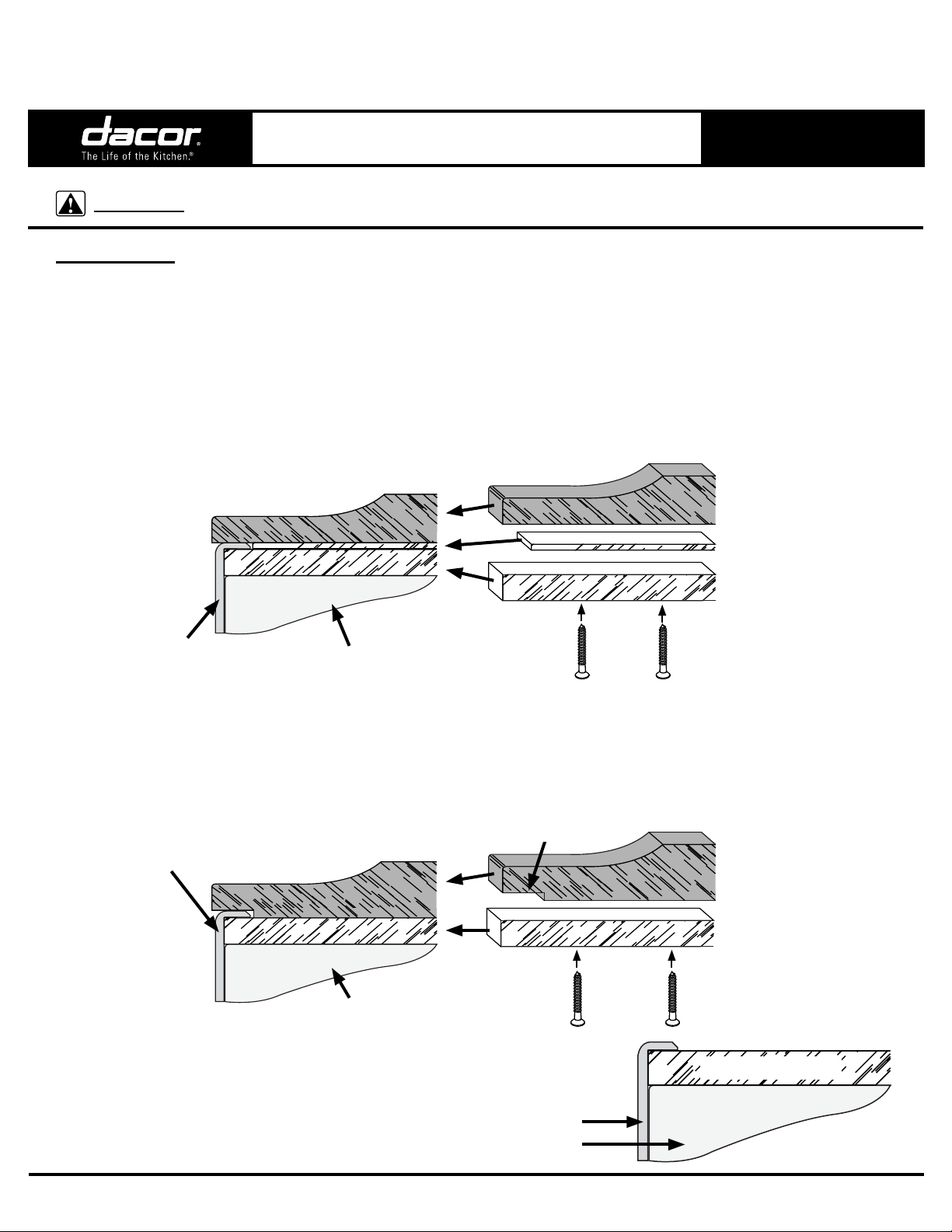
Three Panel Method
The backing panel (1/4” [6 mm] thick) slides behind the trim frames that surround the edges of
each door. The spacer (1/8” [3 mm] thick) compensates for the thickness of the trim frame. The
decorative front panels (3/4” [19 mm] thick maximum) are designed to match the surrounding
cabinets and cover the trim frame around the edges of the door. Countersink the screws used to
assemble the panels.
Front Panel (3/4” Max.)
Spacer Panel (1/8”)
Trim Frame
Surrounding Door
Routed Raised Panel Method
Create a routed raised panel and screw or glue the front panel directly to the 1/4” thick backing
panel. Instead of using a spacer panel, route the edges of the front panel to compensate for the
trim frame thickness. For the top two doors on three door models, do not route the inner edges
because there are no trim frames in the center where the doors come together. Countersink the
screws used to assemble the panels.
Trim Frame
Surrounding Door
Backing Panel (1/4”)
Refrigerator Door
Routed Area
(1/4” W X 1/8” D)
Front Panel (7/8” Max.)
Backing Panel (1/4”)
Refrigerator Door
Single Panel Method
A single 1/4” panel design can be created using the trim
frames to frame the panel (the trim frames will be exposed).
Trim Frame Surrounding Door
Refrigerator Door
Single 1/4” Panel
Part No. 100504 Rev. F
Page 2
IF36 Panel Overlay Installation
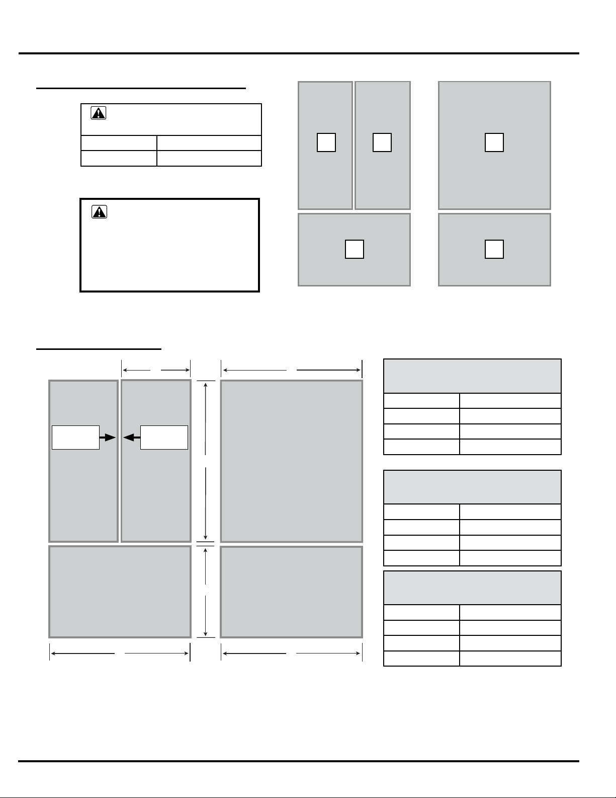
B
A
C
D
D
D
do o r Pa n e l We I g h t SP e c I f I c a t I o n S
Panel Maximum
Weight Specifications
1 15 lb. (7 kg)
2 30 lb. (14kg)
WARNING:
To prevent the unit from tipping
forward and to provide a stable
installation, the refrigerator must
be secured in place with an anti-tip
device.
11
2
11
Model: IF36BNDFSF
Three Doors
Pa n e l SP e c I f I c a t I o n S
No Trim
Frame*
Three Door Model
NOTE: Modification to the dimensions above may be required to allow for
door swing and other considerations depending on the location and type
of cabinet installation.
No Trim
Frame*
Two Door Model
Front Panels
Model: IF36INDFSF
Two Doors
Backing Panel
(Thickness = 1/4”)
A* 17 7/8” (45.4 cm)
B 42” (106.7 cm)
C 23 13/16” (60.5 cm)
D 36 3/16” (91.9 cm)
Spacer Panel - Routed Area
(Thickness = 1/8”)
A* 17 5/8” (44.8 cm)
B 41 1/2” (105.4 cm)
C 23 5/16” (59.2 cm)
D 35 11/16” (90.6 cm)
Front Panel
(Thickness = 3/4”)
A* 18 1/8” (46.0 cm)
B 42 3/16” (107.2 cm)
C 24” (61.0 cm)
D 36 1/2” (92.7 cm)
* On three door models there are no
trim frames on the inner edges of
each door. The inner door surfaces
must be completely finished for a
refined look (see page 3). Stated
dimensions are to the finished edge.
Page 2
Page 3
IF36 Panel Overlay Installation
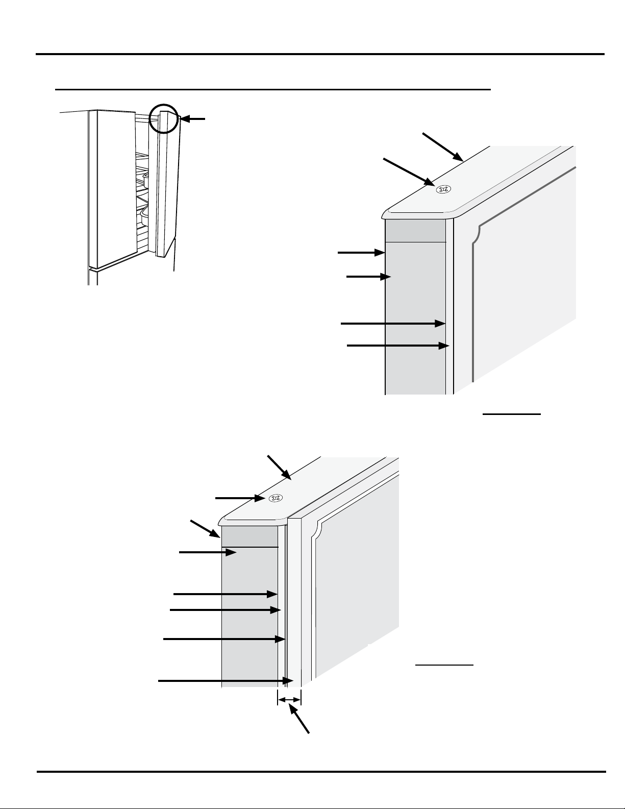
fI n I S h I n g t h e In n e r re f r I g e r a t o r do o r S ed g e S o n th r e e do o r Mo d e l S
See Detail “C”
French Style Refrigerator
Door Detail
and “D”
Back of Door
Black Finished
Refrigerator
Door Surface
Front of Door
Top Trim Frame
Trim Frame
Screw
Trim Frame Screw
Back of Door
Black Finished
Refrigerator
Door Surface
Front of Door
1/4” Backing
Panel
1/8” Spacer
or Front Panel
Inset
Decorative
Front Panel -
3/4” maximum
thickness
Decorative 1/4”
thick panel Finish exposed
edge
Detail “C”
Single Panel Method
Top Trim Frame
Detail “D”
Three Panel and Routed
Raised Panel Methods
Fill all joints and finish
exposed edge
Page 3
Page 4

IF36 Panel Overlay Installation
20" (508m m)
ha n d l e dI M e n S I o n S a n d In S t a l l a t I o n
Before installing a custom panel assembly, you must install •
the custom handle hardware.
Dacor recommends handles with larger D-style pulls. If using •
screws with thick heads, they must be countersunk into the
panel before installing the handles.
Any handle designed for use with an appliance should •
produce satisfactory results.
Mounting screw length varies with the total thickness of the •
panels.
On two door models: The top handle is mounted on the left or •
right side of the door depending on door swing.
IMPORTANT: Dacor advises not using single pull knobs.
Example of
Door Handle
20” Typical
(50.8 cm)
36” Max.
(91.4 cm)
Detail “C”
Double sided
tape between
doors and
panels
Detail “D”
Detail “D”
Detail “D”
Three Door Model Two Door Model
Handle
Door Panel
Counter Sink
Screw
Assembly
Trim Frame
Surrounding Door
Handle
Door Panel
Assembly
Door
Apply two strips of double sided
thin tape between door front and
panel back on each side of door
Detail “C”
Side View - Handle Installation on
Top Doors on three Door Model
Door
Counter Sink
Screw
handle
Detail “D”
Side View - Handle Installation on
All Other Doors
Page 4
Page 5

IF36 Panel Overlay Installation
Pa n e l In S t a l l a t I o n
NOTE: Remove the top door(s) to make panel installation
easier. On three door models secure the inner edges of the
overlays to the door where there are no trim frames using
double sided tape.
With a Phillips screwdriver, remove the trim screws from the •
top trim frame on the freezer and refrigerator door(s).
Remove the trim. •
Lower the overlay panel into the trim frames on the door. •
With the panel in position, replace the top trim. Be sure that •
the panel is inserted completely into the channel for proper
fit and alignment.
Freezer Door
(Bottom - both models)
Left door
Three door models
Refrigerator Doors (Top)
Right door
Two door models
Page 5
Page 6

no t e S
IF36 Panel Overlay Installation
Page 6
Page 7

no t e S
IF36 Panel Overlay Installation
Page 7
Page 8

Specications subject to change without notice.
Dacor assumes no liability for changes to specications.
DacorCorporation●1440BridgeGateDrive,DiamondBar,CA91765●Tel:(800)793-0093●FAX:(626)403-3130●www.Dacor.com
 Loading...