

Page 1
All tolerances: +1/16 (+1.6 mm), -0, unless otherwise stated.
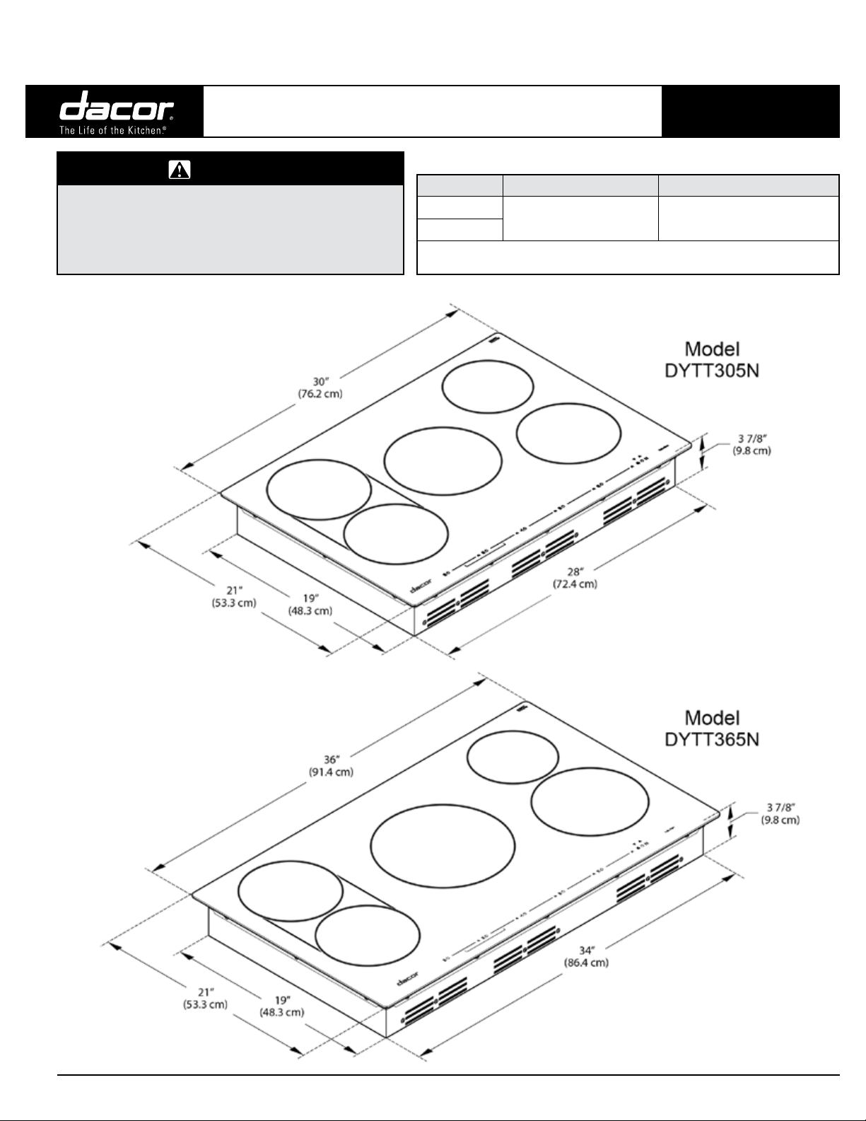
DYTT305, DYTT365
Revised 02/20/17
Discovery® 30” and 36” Wide,
Electric Induction Cooktops
WARNING
• Follow all local codes and ordinances during planning
and installation. (Contact your local building department
for details.)
• This appliance must be installed according to the
accompanying installation instructions.
PLANNING
GUIDE
Electrical-Supply Requirements (reference only)
Model Total Connected Load* Dedicated Circuit Required
DYTT305NB
DYTT365NB
* See the product-data label for the current and exact specifications.
** Two 120V hot (L1 and L2), plus one ground (use all-copper wires in all lines)
46.7 Amp. (11.2 kW)
240V, 60 Hz.
3-Wire** 50 Amp.
• Chassis depth is 1/2” wider and deeper at
the base of the glass cooking surface.
• Cooking surface overhangs the top of the
chassis by 3/4” (1.9 cm) in front, back, and
on both sides.
All specications subject to change without notice.
Phone: (800) 793-0093www.dacor.com
3.12
Page 2
All tolerances: +1/16 (+1.6 mm), -0, unless otherwise stated.
DYTT305, DYTT365
Revised 02/20/17
Discovery® 30” and 36” Wide,
Electric Induction Cooktops
• To reduce risk of burn injury from reaching
over a hot appliance, avoid storage in
cabinetry directly above the cooktop, or install
a range hood.
• Locate the junction box within reach of the 48”
(122 cm) power conduit attached to the bottom
right rear of the chassis. Ensure access to the
bottom of the cooktop chassis and the junction
box for inspection/service.
• To reduce risk of personal injury and smoke
accumulation, Dacor strongly recommends
installing a range hood. Install the hood per
the included installation instructions. The hood
should cover the entire cooktop surface and
project outward at least 5” beyond the bottom
of the overhead cabinets.
• Always consult the countertop manufacturer
for specific installation instructions/
requirements.
The countertop opening must accept the
cooktop chassis’ square corners.
• You may need to include fire-retardant material
(see notes below) in the installation. These
bear the mark:
UNDERWRITERS LABORATORIES INC.
CLASSIFIED
MINERAL AND FIBER BOARDS.
SURFACE BURNING CHARACTERISTICS
This mark is followed by the flame-spread and
smoke ratings. These designations are shown
as “FHC (Flame Spread)/(Smoke Developed).”
Material with “0” flame spread rating are flame
retardant. Local codes may allow other flamespread ratings.
• If the cooktop chassis is completely enclosed,
allow ventilation of at least 18 square inches
into the enclosure.
PLANNING
GUIDE
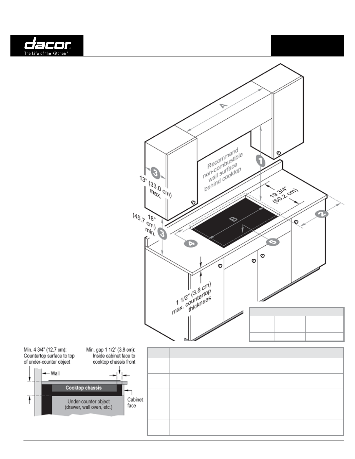
Cabinet Cutout Dimensions
Cabinet Clearances
Model A B
DYTT305 30” (76.2 cm) 28 3/4” (73.0 cm)
DYTT365 36” (91.4 cm) 34 3/4” (88.3 cm)
Under-Counter Clearance
All specications subject to change without notice.
Callout Description
30” min. clearance from cooktop surface and bottom of unprotected wood or metal
1
cabinet
Distance to combustible side wall (either side): 2 1/4” (5.7 cm) min. from edge of cooktop
2
surface.
If cooktop side of upper cabinetry is more than 2 1/4” (5.7 cm) to the left/right of the
3
cooktop edge, Specification 3 does not apply.
1 1/8” (2.9 cm) min. to combustible surface at rear; 3/4” (1.9 cm) min. to non-
4
combustible surface at rear.
Ensure internal space allows proper under-cabinet ventilation for cooktop chassis. (See
5
Cooktop Clearance/Ventilation, Pg. 2.)
Phone: (800) 793-0093www.dacor.com
3.13
Page 3

All tolerances: +1/16 (+1.6 mm), -0, unless otherwise stated.
DYTT305, DYTT365
Revised 02/20/17
Discovery® 30” and 36” Wide,
Electric Induction Cooktops
PLANNING
GUIDE
Inset Cutout Installation Dimensions
IMPORTANT (INSET CUTOUT)
See the previous page for minimum clearances to combustibles
and overhead cabinets.
Cooktop Width Dimensions
Model A (inset cut) B (through cut)
DYTT305 30 1/8” (76.5 cm) 28 3/4” (73.0 cm)
DYTT365 36 1/8” (91.8 cm) 34 3/4” (88.3 cm)
DYTT Cooktop w/Downdraft Cutout Dimensions
Model Conguration
DYTT305 cooktop w/ERV3015/PRV30 28 3/4” (73.0 cm) 27 3/4” (70.5 cm)
DYTT365 cooktop w/ERV3615/PRV36 34 3/4” (88.3 cm) 33 3/4” (85.7 cm)
(C) Cooktop
Cutout Width
(D) Downdraft
Cutout Width
Flush Cutout Installation Dimensions
(downcraft vent system)
IMPORTANT (FLUSH CUTOUT/
DOWNDRAFT VENT)
• See the previous page for minimum clearances to
combustibles and overhead cabinets.
• Install only the downdraft models specified in the DYTT
Cooktop w/Downdraft Cutout Dimensions table (below).
• If installing the cooktop with a downdraft flush with the
countertop, see the Countertop Inset-Cutout Dimensions
section (this page).
• The countertop inset for the downdraft must be lower to
accommodate the downdraft’s top cap, which extends the
height of the downdraft. (See the downdraft’s installation
instructions to determine the exact dimensions.)
• Additional sealing is required between the cooktop chassis and
the downdraft due to the difference in the required inset depth.
(E) Total
Cutout Width
22 1/2” (57.2 cm) 2 3/4” (7.0 cm) 3/8” (1.0 cm)
(F) Downdraft
Cutout Depth
(G) Min. Rear
Counter Overhang
DYTT305 cooktop w/RV30 downdraft 28 3/4” (73.0 cm) 27 3/4” (70.5 cm)
DYTT365 cooktop w/RV36 downdraft 34 3/4” (88.3 cm) 33 3/4” (85.7 cm)
All specications subject to change without notice.
22 1/4” (56.5 cm) 2 1/2” (6.4 cm) 5/8” (1.6 cm)
Phone: (800) 793-0093www.dacor.com
3.14
Page 4

All tolerances: +1/16 (+1.6 mm), -0, unless otherwise stated.
DYTT305, DYTT365
Revised 02/20/17
Discovery® 30” and 36” Wide,
Electric Induction Cooktops
When installing a DTO, DYO, or RNO wall oven with a DYTT
cooktop, you cannot use a downdraft vent system. Because
standard floor-cabinet depth is 24”, and the wall oven depths
are all 24”, there is no space for the downdraft vent behind the
cooktop. A hood venting system must be used when installing
a wall oven under a DYTT cooktop in standard-depth cabinets.
PLANNING
GUIDE
IMPORTANT
Cooktop/Wall Oven
Combination
Combination DYTT Cooktop/Wall Oven Installation Dimensions
Wall Oven
Model No.
DTO 32 3/8” (82.2 cm) 19 3/4” (50.2 cm) 1 1/8” (2.9 cm) 2 3/4” (7.0 cm) 2 3/4” (7.0 cm)
DYO 33 1/8” (84.1 cm) 19 3/4” (50.2 cm) 1 1/8” (2.9 cm) 2 3/4” (7.0 cm) 2 3/4” (7.0 cm)
RNO 32 3/8” (82.2 cm) 19 3/4” (50.2 cm) 1 1/8” (2.9 cm) 2 3/4” (7.0 cm) 2 3/4” (7.0 cm)
All specications subject to change without notice.
(A) Min. C’top to
Oven Platform
(B) Cutout Depth
(C) Min. Back of
Cutout to Wall
(D) Min. Front o’ C’top
to Front o’ Cutout
(E) Min. Cab’t Face
to Front of Cutout
Comments
Leave minimum 7 sq. in. ventilation through
cabinet; min. 2 in. betw. front of chassis
and back of cab’t below c’top. (See DYTT
planning guide.)
Phone: (800) 793-0093www.dacor.com
3.15
 Loading...