

Page 1
RNRP30G, RNRP36G, RNRP48G
Document # PG05-012
Renaissance 30”, 36” and 48”
Gas Ranges
Cabinet Layout
■ All maximum and minimum dimensions and clearances shown
in the diagrams below must be maintained for safe operation.
■ The range should be placed away from drafts that may be
caused by doors, windows and heating and air conditioning
outlets.
■ Avoid cabinet installations directly above the range. If cabinet
storage is to be provided above the range, the risk can be
reduced by installing a range hood that projects horizontally a
minimum of 5 inches beyond the bottom of the cabinets.
■ The range may be installed flush to the rear wall. Dacor
strongly recommends installing a non-combustible material
on the rear wall above the range and up to the vent hood or
installation of a backguard.
■ Any openings in the wall behind the appliance or in the floor
underneath it must be sealed.
DIMENSIONS: SEE TABLE ON FOLLOWING PAGE
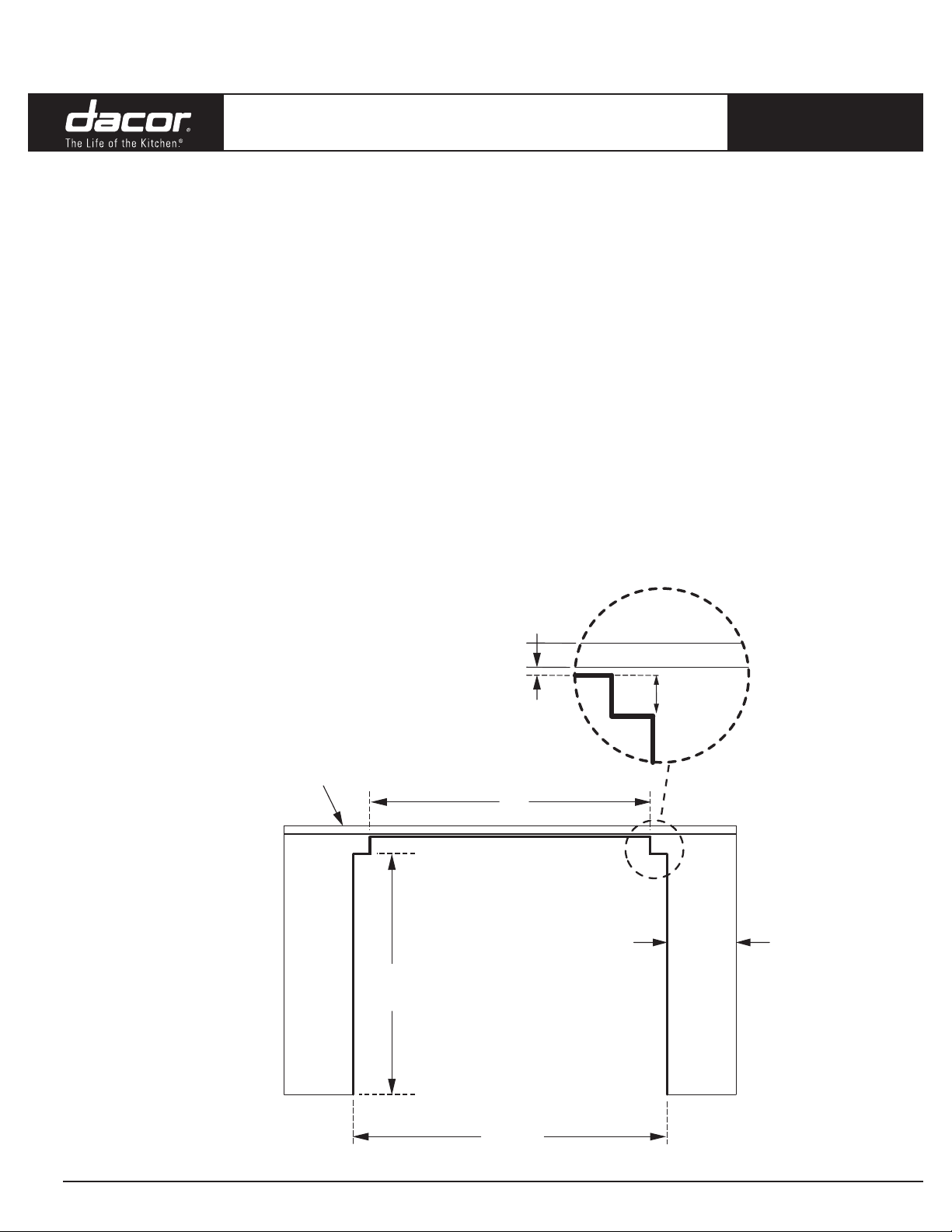
Cutout tolerances: +1/16” 0” (1.6 mm)
unless otherwise stated.
Revised 08/21/15 Page 1/4
PLANNING
GUIDE
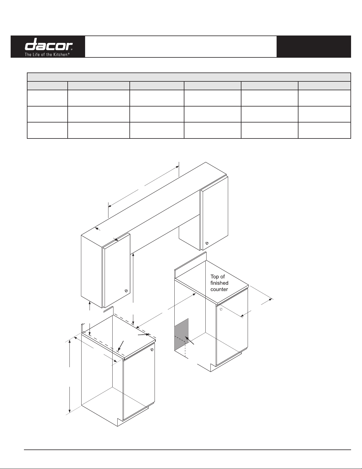
■ The shaded area in the Recommended Cabinet Clearance
Dimensions figure shows the recommended locations of the
gas inlet and the electrical junction box. For replacement
purposes, the location of the existing utilities may be used
provided they do not interfere with the sides or rear of the
range.
■ The junction box and gas shut off valve must be located
so that the range can be pulled out for service while the
appliance remains connected.
■ An external, manual shut-off valve must be installed between
the gas inlet and the range for the purpose of turning on or
shutting off gas to the appliance.
The installation must allow for the following:
■ Access to the gas shut-off valve when the unit is installed.
■ Access to the remote circuit breaker panel/fuse box, when the
range is in place.
■ The gas supply piping and shut-off valve, and the electrical
junction box must be located so they do not interfere with the
range when it is installed.
RANGE CUTOUT WITH OPTIONAL
DOWNDRAFT SPACING
(TOP VIEW)
non-combustible
rear wall (recommended)
Note 2
Next page
Backsplash
J
3/8" (1.0 cm)
min. for downdraft cap
clearance
H
10" (25.4 cm) min.
to combustible side
walls above the range
(both sides)
All specications subject to change without notice.
G
Phone: (800) 793-0093www.dacor.com
Page 2
Document # PG05-012
Note 2
F
G
2
Cabinet/countertop depth is at discretion of customer but
cabinet face MUST NOT protrude further than rear of front
panel, see product dimensions.
3
Consult local code for exact location requirements.
1
Vertical from range grate level to combustible overhead
surface; if installing an overhead vent hood, also check
hood specifications for minimum required clearances.
4
Vertical from grate level to combustible surface.
Non-combustible
surface along back wall
recommended
10” (25.4 cm) min.
to combustible side
walls above the range
(both sides)
30” (76.2 cm)
min.
1
37 1/2”
(95.3 cm)
max.
13” (33.0 cm)
max.
5
15” (38.1 cm)
min.
4, 5
5
This specification does not apply for cabinets more
than a horizontal distance of 10” (25.4 cm) from the
edge of the range.
Suggested
location of
utilities
3
Grate
level
RNRP30G, RNRP36G, RNRP48G
Revised 08/21/15 Page 2/4
Renaissance 30”, 36” and 48”
Gas Ranges
All tolerances +1/16” -0” (+1.6 mm) unless otherwise noted.
CUTOUT DIMENSIONS
Range Model F G H I J
RNRP30G
RNRP36G
36” (91.4 cm) *
30” (76.2 cm) **
42” (106.7 cm) *
36” (91.4 cm) **
RNRP48G 54” (137.2 cm) *
48” (121.9 cm) **
30”
(76.2 cm) **
36”
(91.4 cm) **
48”
(121.9 cm) **
27 1/2”
33 1/2”
(84.8 cm)
43 1/2”
(110.2 cm)
30 1/2”
(77.5 cm)
30 7/8”
(78.4 cm)
29 7/8”
(75.9 cm)
PLANNING
GUIDE
* Recommended **Minimum
MINIMUM CABINET
CLEARANCE DIMENSIONS
3 1/2”
(8.9 cm)
3”
(7.6 cm)
3”
(7.6 cm)
All specications subject to change without notice.
Phone: (800) 793-0093www.dacor.com
Page 3

48” (121.9 cm)
Front of open door
Front of handle
Front of bull nose
Front panel
Rear of front panel/oven door
28 1/2” (72.4 cm)
(91.9 cm)
36 3/16”
(95.3 cm)
37 1/2”
26 7/8” (68.3 cm)
26” (66.0 cm)
24” (61.0 cm)
1 1/4”
(3.2 cm)
to
1 1/16” (2.7 cm) to cooking
surface (top of grates) from
top of trim
3” Standard height or
1.5” and 9” are available
Document # PG05-012
downdraft vent
RNRP30G, RNRP36G, RNRP48G
Revised 08/21/15 Page 3/4
Renaissance 30”, 36” and 48”
Gas Ranges + ERV Downdrafts
Product Dimensions
Product tolerances: +/- 1/16” (+/- 1.6 mm) unless otherwise stated
Range Part Numbers
RNRP30G RNRP36G RNRP48G
PLANNING
GUIDE
WARNING
• Observe all governing codes and ordinances during planning
and installation. Contact your local building department for
further information.
• This appliance must be installed in accordance with the
accompanying installation instructions.
Width (Front) Dimensions
RNRP30G 29 7/8” (75.9 cm)
RNRP36G 35 7/8” (91.1 cm)
RNRP48G 47 7/8” (121.6 cm)
RNRP30G RNRP36G RNRP48G
Downdraft
Model #
1.5-inch
Low Prole
Backguard
Accessory #
IMPORTANT: See the ERV downdraft installation instructions
for duct and electrical requirements.
Use only the Dacor downdraft models specified in the table.
Trim kit accessory is required only on the 30-inch range +
downdraft configuration.
plus Trim Kit #
ATKERV-RP30
APB30GLP APB36GLP APB48GLP
ERV3015
ERV36-ER ERV48-ER
RNRP ranges are shipped with a 3-inch backguard. A
downdraft can be used; however, a 1.5-inch backguard is
recommended.
All specications subject to change without notice.
3/8” min. (1.0 cm) for
downdraft cap clearance
I (to back of downdraft)
Countertop
Back of
control
panel
Cabinet face
Downdraft Part Numbers
ERV3015 (for 30G)
ERV36-ER (for 36G)
ERV48-ER (for 48G)
Backguard
Stiffener
Phone: (800) 793-0093www.dacor.com
3/8” min.
(1.0 cm)
space behind
chassis to
clear stiffener
Page 4

Document # PG05-012
B
A
RNRP30G, RNRP36G, RNRP48G
Revised 08/21/15 Page 4/4
Renaissance 30”, 36” and 48”
Electrical and Gas Requirements
Gas Ranges
PLANNING
GUIDE
Range
Model
RNRP30G
RNRP36G
RNRP48G
A B
13 1/16” to 14 3/8”
(33.2 to 36.5 cm)
13 1/16” to 14 3/8”
(33.2 to 36.5 cm)
13 1/16” to 14 3/8”
(33.2 to 36.5 cm)
4 5/16”
(12.16 cm)
7 5/16”
(18.6 cm)
4 1/4”
(10.8 cm)
BACK OF RANGE
Gas
Type
Natural 5” 6” 1/2 psi
LP 10” 11” 1/2 psi
120 Vac, 60 Hz, 15 Amp.
Grounded, dedicated, 3- prong
GAS SUPPLY PRESSURE REQUIREMENTS
Manifold
Pressure*
(WC)
Min. Gas
Supply
Pressure (WC)
Max. Input
Pressure
ELECTRICAL REQUIREMENTS
For 30”, 36” and 48” Ranges
Electrical Circuit
Required
electrical outlet
Total Connected
Load
5.0 Amps. @120 Vac,
60 Hz,
IMPORTANT: The information above is for reference only. If the above data does not agree with the product data label, use
the data on the product data label on top of the kick plate below the door (see the installation instructions for location).
The range comes from the factory with the regulator installed. Use only the installed regulator. The regulator inlet
accommodates a 3/4” gas line. The range ships with a 1/2” to 3/4” adapter connected to the regulator.
All specications subject to change without notice.
Phone: (800) 793-0093www.dacor.com
 Loading...