

Page 1
HDPRS/HDERS
Doc #: PGH-HDPR/ER.01 Revised 22 May 2018 Page1 of 3
All tolerances: ±¹/₁₆” (±1.6 mm), unless otherwise stated.
Heritage®30”, 36”, 48” Wide,
WARNING
• Observe all governing codes and ordinances
during planning and installation. Contact your
local building department fordetails.t
• The range must be installed as specified in its
installation instructions.
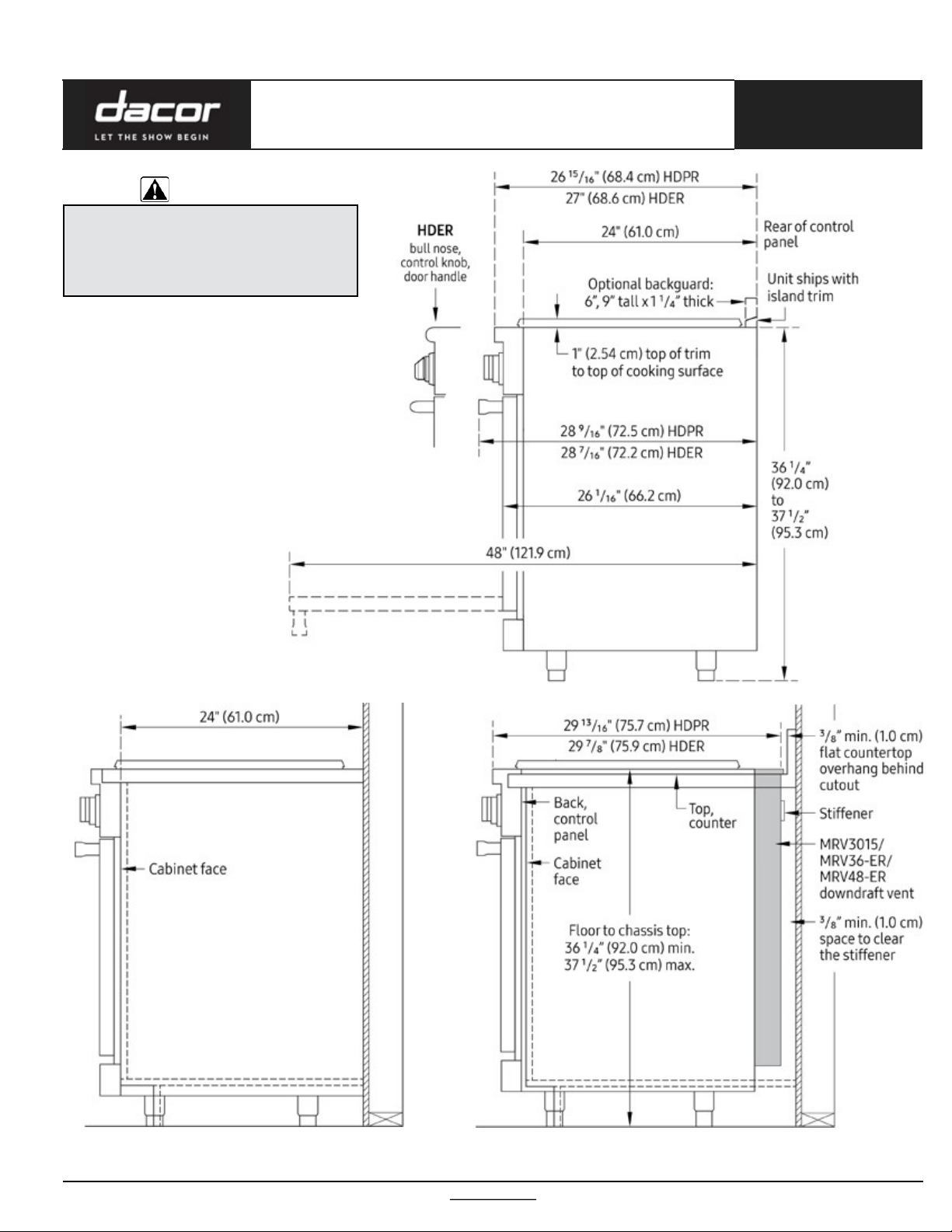
Critical Depth/Height Dimensions
HDPRS model shown; commondimensions given;
unique HDPRS/HDERS dimensions indicated
Dual-Fuel Ranges
PLANNING
GUIDE
Range-With-Downdraft InstallationRange-Only Installation
All specifications subject to change without notice. www.dacor.com Ph. 800.793.0093
Page 2
HDPRS/HDERS
All tolerances: ±¹/₁₆” (±1.6 mm), unless otherwise stated.
Page 2 of 3
Heritage®30”, 36”, 48” Wide,
Dual-Fuel Ranges
ELECTRICALREQUIREMENTS
Model Required Circuit Total Connected Load
HDPR30S, HDER30S
240 Vac*, 60 Hz,30 Amp. 5.75 kW (24.0Amp.)
HDPR36S,HDER36S
HDPR48S, HDER48S 240 Vac*, 60 Hz,50 Amp. 10.1 kW (41.9Amp.)
*4-wire, two 120 Vac hot (L1 and L2), one neutral, one ground; these ratings are for
reference only; see the range's data label (backof range) forexact specifications.
The wiring must be long enough that the range can be pulled out
for service, without being disconnected.Wiring to the range must:
• meet NEMA standards and the requirements in the abovetable
• include a strain relief
• be terminated by tinned leads, closed-loop terminals, oropenended spade lugs with upturned ends
• connect to a junction box or receptacle installed by a licensed
electrician.
The range maybe connected via one of these two methods:
• 4-wire conduit connected to a 4-wire junction box
• 3-wire conduit (where local code permits, not for use with new
branch circuit installations) connected to a 3-wire junction box.
Using a power cord:
• A 4-wire power cord with a NEMA14-50P plug connected to a
NEMA 14-50R receptacle:
PLANNING
GUIDE
MINIMUM GAS-SUPPLY PRESSURE REQUIREMENTS*
Gas Type Min. Manifold Pressure Min. Gas-Supply Pressure**
Natural 5” watercolumn 6” watercolumn
LP(propane) 10” watercolumn 11” watercolumn
*Gas-supply pressure for testing the regulator setting shall be at least 1” water
column (249 Pa) above the specified manifold pressure; **Max gas-supply pressure, all models: 1/2 psi.
The above ratings are forreference only; see the rating label (upper-rearof
range) for exactspecifications.
• A 3-wire power cord (where permitted) with a NEMA10-50P
plug connected to a NEMA 10-50Rreceptacle
• The power-cord plug must be UL listed type SRD or SRDT.
• Range models DYRP36D-C-S and DYRP48D-C-S come with a
factory installed 4-wire appliance cord with NEMA 14-50P plug.
For freestanding ranges installed in Canada, a factory installed
4-wire appliance cord with NEMA 14-50P plug is required,
without modification.
48” modelshown
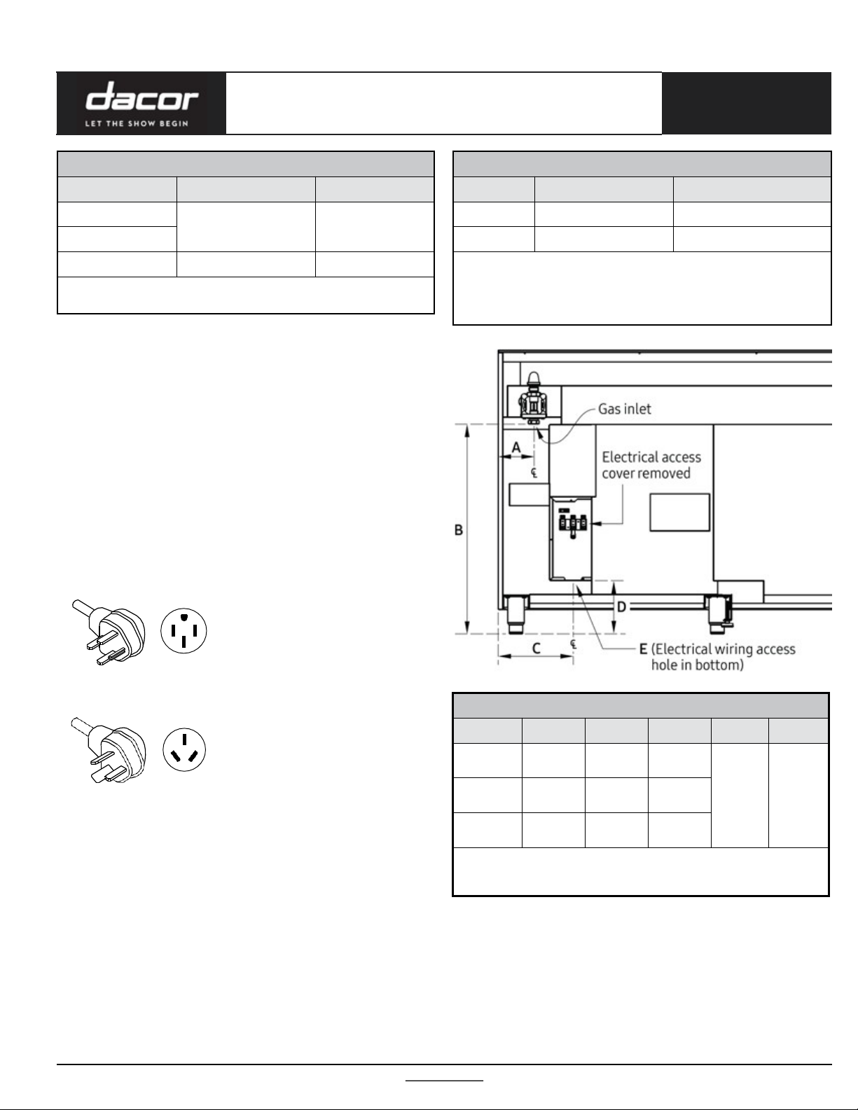
GAS-/ELECTRICAL-ACCESS DIMENSIONS
Model A B* C D* E**
HDPR30S/
HDER30S
HDPR36S/
HDER36S
HDPR48S/
HDER48S
*Measurement with range legs adjusted to their lowest height; **the hole
size for the electrical wiring may be increased to 11/8”(2.9 cm) by removing the
conduit bracketin the bottom of the electrical box.
3 1/4"
(8.3 cm)
6 3/4"
(17.1 cm)
4 1/4”
(10.8 cm)
27”
(68.6 cm)
27”
(68.6 cm)
27”
(68.6 cm)9”(22.9 cm)
6 3/4"
(17.1 cm)
12”
(30.5 cm)
6 3/4
(17.1 cm)
7/8”
(2.2 cm)
dia.
All specifications subject to change without notice. www.dacor.com Ph. 800.793.0093
Page 3

HDPRS/HDERS
All tolerances: ±¹/₁₆” (±1.6 mm), unless otherwise stated.
Page 3 of3
Heritage®30”, 36”, 48” Wide,
Dual-Fuel Ranges
Cabinet Layout
• All maximum/minimum dimensions and clearances in the
diagrams below must be maintained for safeoperation.
• Place the range away from drafts (open doors and windows,and
home heating/cooling systems).
• Do not install cabinets over the range, or to reduce risk of burn
injury from reaching over a hot cooktop, install a range hood that
projects horizontally at least 5” beyond the cabinet bottoms.
• The range may be installed against the rear wall. Dacorstrongly
recommends installing a backguard or non-combustible
material on the rear wall between the range vent hood.
CUTOUT DIMENSIONS
Model F: recommended/min. G: min./max. H
HDPRS/HDERS 30 36” (91.4 cm) / 30” (76.2cm) 30” (76.2 cm) / 30 1/8” (76.5cm) 27 3/8" (69.5 cm)
HDPRS/HDERS 36 42” (106.7 cm) / 36” (91.4cm) 36” (91.4 cm) / 36 1/8” (91.8cm) 33 1/2” (84.8cm)
HDPRS/HDERS 48 54” (137.2 cm) / 48” (122.0 cm) 48” (121.9 cm) / 48 1/8” (122.2 cm) 43 1/2” (110.5cm)
Standard Cutoutwith
Range Hood
• Seal openings in the wall behind the range and in the floor below.
• The grey area in the diagram below shows the suggested gas/
electrical utilities. Existing utilities may be used if they do not
hinder rangeplacement.
• Gas/electrical utilities must be located so the range can be
moved for service without beingdisconnected.
• An external, manual shut-off valve must be installed between
the gas inlet and range so gas to the range can be shut on/off.
• Installation must allow access to the gas shut-off valve and
circuit-breaker panel/fuse box when the range is in place.
PLANNING
GUIDE
APPROVED DOWNDRAFT VENTS
Range Downdraft Vent
HDPRS/HDERS 30 MRV3015
HDPRS/HDERS 36 MRV36-ER
HDPRS/HDERS 48 MRV48-ER
IMPORTANT: See downdraft installation instructions for duct and electrical installation requirements. Use only approved Dacordowndraft vents.
Countertop Cutout ForDowndraft Vent
1. Vertical from range grate level to combustible overhead surface; if install-
ing an overhead hood, see hood specifications for minimum required
clearances.
2. Cabinet/countertop depth is at customer discretion, but cabinet face must
not protrude beyond rear of range front panel. (See Pg. 1for dimensions.)
3. Consult localcodes for exact location requirements.
4. Vertical from grate level to combustible surface.
5. Not applicable to cabinets that horizontally are over10” (25.4 cm) from
range edge.
All specifications subject to change without notice. www.dacor.com Ph. 800.793.0093
 Loading...