

Page 1
HDCT304, HDCT365
Doc #: PGH-HDCT3036.01 Revised 29 Jan 2019 Page 1 of 5
All tolerances: ±¹/₁₆” (±1.6 mm) unless otherwise stated.
Heritage
®
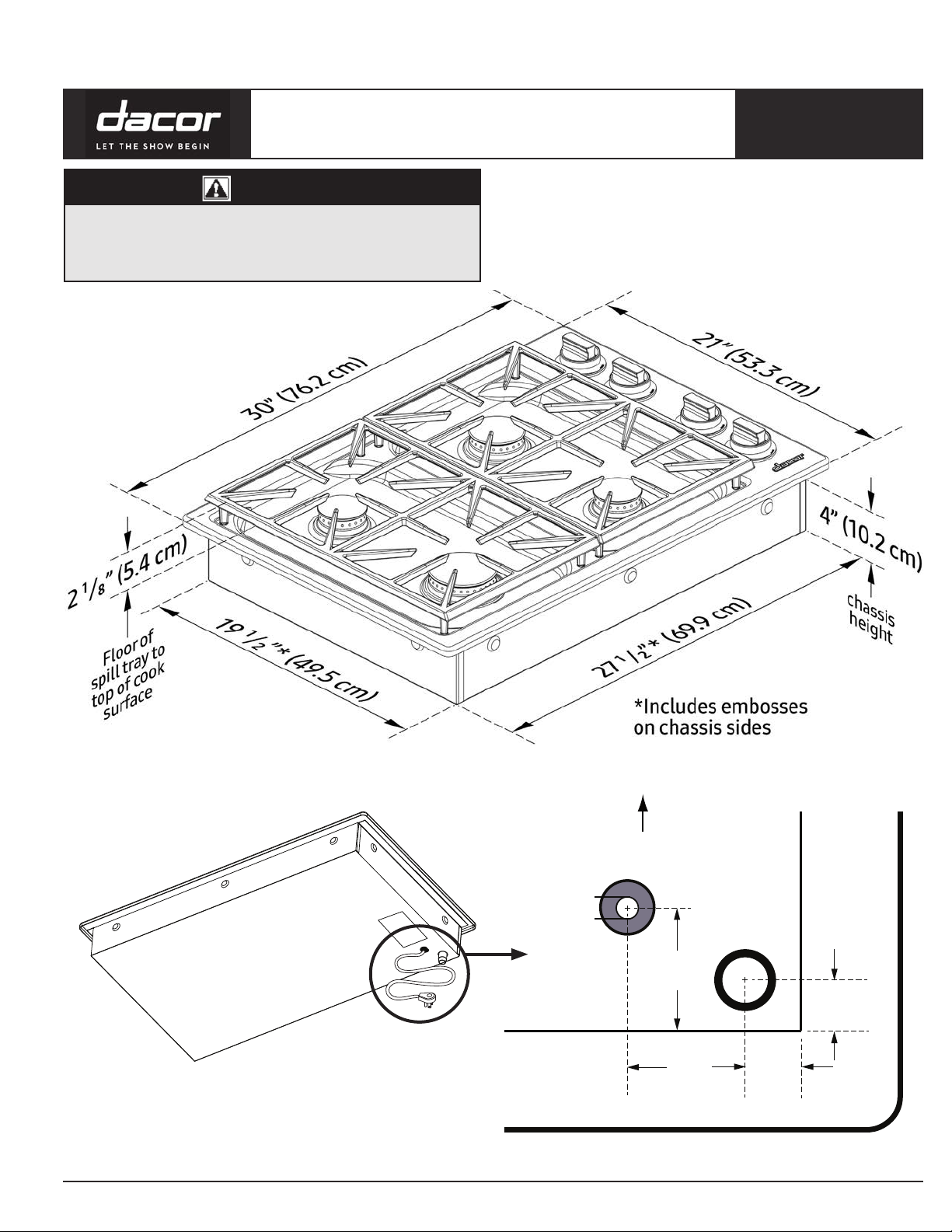
30”, 36” Dual Cooktop
WARNING
• Observe all governing codes and ordinances during planning/
installation.
• Contact the local building department for details. This cooktop must
be installed as specified in its installation instructions.
HDCT304
PLANNING
GUIDE
Front of cooktop
Power cord
Gas inlet
2 1/8”
HDCT304
Chassis
(5.4 cm)
3 3/4”
(9.5 cm)
13/16”
5/8”
(1.6 cm)
(2.1 cm)
Power Cord and Gas-Inlet Location
Top panel overhang
All specications subject to change without notice. www.dacor.com Ph. 800.793.0093
Page 2

HDCT304, HDCT365
All tolerances: ±¹/₁₆” (±1.6 mm) unless otherwise stated.
Page 2 of 5
HDCT365
Heritage
®
30”, 36” Dual Cooktop
PLANNING
GUIDE
HDCT365
Power Cord and Gas Inlet Location
Chassis
Gas inlet
Front of cooktop
Power cord in
2 1/4”
(5.7 cm)
1 3/8”
(3.5 cm)
Top panel overhang
1”
(2.5 cm)
1”
(2.5 cm)
All specications subject to change without notice. www.dacor.com Ph. 800.793.0093
Page 3

HDCT304, HDCT365
All tolerances: ±¹/₁₆” (±1.6 mm) unless otherwise stated.
Page 3 of 5
Heritage
®
30”, 36” Dual Cooktop
Electrical Requirements
WARNING
To prevent electric shock, the power supply must meet the given
specifications. The owner shall ensure that the electrical service meets
requirements and that the power outlet is properly installed by a
licensed electrician.
• The cooktop has a 40-in.power cord with 3-prong grounding plug on
the chassis’ bottom right-rear corner.
HDCT304
HDCT365
PLANNING
GUIDE
Gas-Supply Requirements
• Ensure the cooktop is correct for the gas (natural or liquid propane)
provided. If using the cooktop above 4000 ft. (1219 m) elevation,
ensure it is equipped for high-elevation operation.
• Units equipped for liquid propane have “LP” in the model number on
the product data label (previous graphic).
• Units equipped for high-elevation use have an “H” at the end of the
model number on the product data label.
• Install the cooktop according to local building codes; if none exist,
install the appliance according to the National Fuel Gas Code ANSI
Z223.1/NFPA 54.
• An external manual shut-off valve must be installed between the gas
inlet and cooktop so gas to the appliance can be turned on/off.
• The cooktop comes with its own regulator, which must be installed in
the gas line from the cooktop gas inlet to the gas shut-off valve. Use
only the regulator provided.
• The cooktop has a ¾-in. regulator approved for connection to a ½-in.
house gas supply.
• The cooktop gas connection is on the chassis bottom in the right-rear
corner (previous graphic).
Gas and Electrical Requirements*
• The cooktop must be connected to a dedicated, grounded 3-prong
electrical outlet installed by a licensed electrician.
• The electrical installation, including supply-wire size and grounding,
must be done according to National Electric Code ANSI/NFPA 70* and
local codes and ordinances. A copy of this standard is available from:
National Fire Protection Association
1 Batterymarch Park
Quincy, MA 02269-9101
• The correct voltage, frequency, and amperage must be supplied to the
electrical outlet according to the data label (see previous graphic).
• See the Gas/Electrical Requirements table (this page).
• Choose an easily accessible electrical outlet so the cooktop can be
unplugged for service/maintenance.
Data Type*
Gas type Natural Gas LP Gas
Manifold pressure 5” water column 10” water column
Min. gas-supply pressure** 6” water column 11” water column
Max. gas-supply pressure ½ psi
Total connected load 0.25 Amp. (0.03 kW)
Circuit requirement 120 Vac, 60 Hz, 15 Amp
*This data is for reference only. If it does not agree with the product data label,
use the data on the product data label; **the gas-supply pressure for testing
the regulator setting shall be at least 1” water column (249 Pa) above the
specified manifold pressure.
HDCT304/NG,
HDCT365/NG
HDCT304/LP,
HDCT365/LP
All specications subject to change without notice. www.dacor.com Ph. 800.793.0093
Page 4

HDCT304, HDCT365
13" max.
(33.0 cm)
A
15" min.
1
(38.1 cm)
1 7/8" min.
(4.8 cm)
Combustible
surface to rear
Combustible overhead
cabinets
30" min.
1, 2
(76.2 cm)
See Note 3
See cutout
dimensions
1/4” (6 mm)
min. height clearance
to combustible
surfaces
B
Underneath Cabinet Dimensions
All tolerances: ±¹/₁₆” (±1.6 mm) unless otherwise stated.
Page 4 of 5
Heritage
®
30”, 36” Dual Cooktop
Cabinet and Countertop Layout
WARNING
• To reduce risk of personal injury from reaching over a hot cooktop,
avoid cabinet storage over the cooktop.
• Failure to meet or exceed the maximum and minimum dimensions/
clearances as instructed may cause a fire hazard.
• Follow the countertop manufacturer’s instructions regarding all
aspects of countertop installation.
• Carefully check the cooktop installation site. Situate the
cooktop away from drafts and wet areas.
• Use the cooktop with a suitable vent hood or approved Dacor
downdraft.
PLANNING
GUIDE
Model (A) Minimum (A) Maximum
HPCT304G 30” (76.2 cm) 36” (91.4 cm)
HPCT365G 36” (91.4 cm) 42” (106.7 cm)
Model (B) Minimum for clearance of hold-down brackets
HDCT304 29 in (73.7 cm)
HDCT365 35 1/4 in (89.5 cm)
Installation must allow:
• At least ” (6 mm) clearance between the bottom of the
cooktop chassis and all combustible surfaces, including the
edges and corners of drawers under the cooktop.
• Clearance for hold-down brackets
• The gas supply piping, gas shut-off valve, and electrical outlet
must not interfere with the installed cooktop.
• If installing an appliance below the cooktop, allow for routing of
utilities behind it.
• Access to the gas shut-off valve and regulator without moving
the cooktop.
• The 40” (101.6 cm) power cord to reach an electrical outlet, and
outlet to be accessable without moving the cooktop.
• Access to the cooktop bottom for service/maintenance (Do not
install fixed shelving below the cooktop).
All specications subject to change without notice. www.dacor.com Ph. 800.793.0093
Callout Description
1 Measured from top of cooktop grate
If installing with an overhead vent hood, also check hood
2
specifications for minimum required clearances.
Not applicable for cabinets more than a horizontal distance
3
of 6” (15.2 cm) from edge of cooktop.
Downdraft Compatibility
If installing the cooktop with a downdraft, use only the approved
Dacor model numbers MRV3015 or MRV3615. (See Pg. 5.)
Model Approved Downdraft Models
HDCT304 MRV3015S
HDCT365 MRV3615S
Page 5

HDCT304, HDCT365
3/8” min. (1.0 cm)
All tolerances: ±¹/₁₆” (±1.6 mm) unless otherwise stated.
Page 5 of 5
Countertop Cutout View
Vertical
combustible
surface
C
Heritage
Rear
wall
D
1 7/8" min.
(4.8 cm)
®
30”, 36” Dual Cooktop
4 1/4" (10.8 cm) min.
from mounting surface to
combustibles below
cooktop chassis
E
F
Min. distance to combustible side
wall above countertop (both sides)
CUTOUT TYPE AND DIMENSIONS
PLANNING
GUIDE
F
Installation Type (C) Minimum (D) (E) (F)
HDCT304 (no downdraft) 2 ” (7.3 cm) 19 ” (50.2 cm)
HDCT304 (with MRV3015S) ” (1.0 cm) 22 ” (57.2 cm)
HDCT365 (no downdraft) 2 ” (7.3 cm) 19 ” (50.2 cm)
HDCT365 (with MRV3615S) ” (1.0 cm) 22 ” (57.2 cm)
3/8” (1.0 cm)
needed for downdraft
required for downdraft
cap clearance
cap clearance
23 3/8” (59.4 cm)
23 3/8” (59.4 cm)
Stiffener
Stiffener
DYCT Gas Cooktop
HDCT Gas Cooktop
HDCT Gas Cooktop
HPCT Gas Cooktop
Cabinet face
Cabinet face
3/8” (1.0 cm) min. space
3/8” min. (1.0 cm) space
behind downdraft
behind downdraft
to clear stiffener
to clear stiffener
MRVxx15S series
ERV or PRV Series
downdraft: Check downdraft
Downdraft: check
specifications to determine
downdraft specifications
correct fit
to determine correct fit
27 ” (70.1 cm) 7 ½” (19.1 cm)
33 ” (85.7 cm) 7” (17.8 cm)
Countertop
Countertop
Floor
Floor
Cooktop with Downdraft: MRV Series
All specications subject to change without notice. www.dacor.com Ph. 800.793.0093
 Loading...