

Page 1

Installation Instructions
Heritage® Series Gas Cooktop
Models HCT305G, HCT365G
Part No. 113554 Rev. B
Page 2
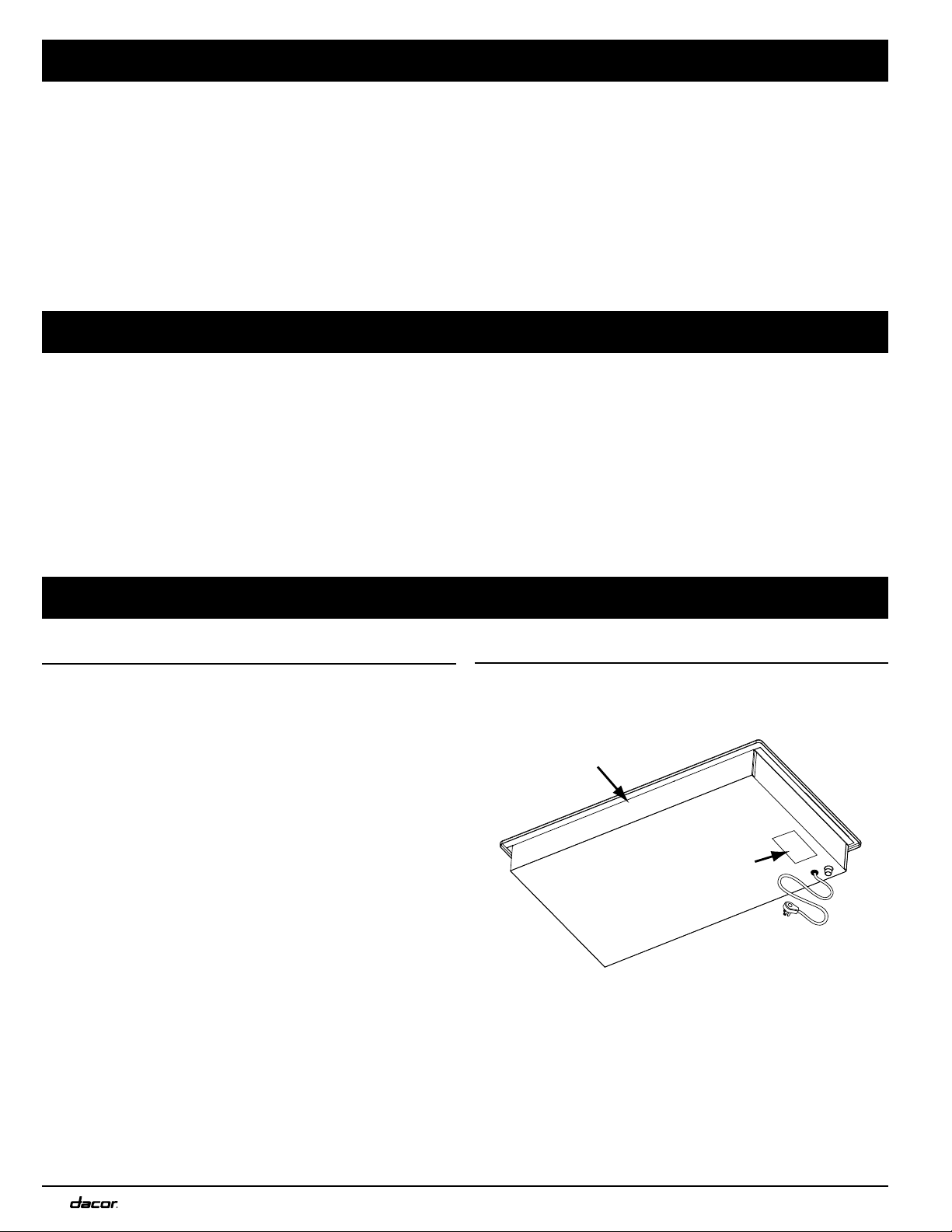
Table of Contents
Important Safety Instructions .........................................................1
Important Information ...................................................................... 1
General Safety Precautions ..............................................................2
Electrical Requirements ...................................................................3
Gas-Supply Requirements ................................................................3
Installation Specifications ...............................................................4
Product Dimensions ..........................................................................4
Cabinet and Countertop Layout ......................................................5
Installation Instructions ................................................................... 7
Verifying Package Contents ............................................................. 7
Installing the Cooktop ....................................................................... 7
Connecting the Gas Line ...................................................................7
Assembling the Burners ...................................................................8
Placing the Grates..............................................................................9
Verifying Proper Function ...............................................................10
Troubleshooting ...............................................................................10
Installer Checklist ............................................................................ 11
Wiring Diagram ............................................................................... 11
Before You Begin…
Installer
• For safety reasons and to minimize problems, read this Installation Instruction manual thoroughly before installing the appliance.
• Leave the Installation Instructions manual with the consumer.
• Write the Product Data Label information in the Use and Care manual for the consumer’s reference.
Consumer
Keep the Installation Instructions manual for reference and for the local electrical inspector’s use.
Note: Dacor
®
is not responsible for service required to correct a faulty installation.
Customer Assurance Information
If You Need Help…
…with installation and warranty questions and issues, contact
your Dacor dealer or Dacor Customer Assurance.
When you call, have available the cooktop model and serial numbers, which are on the data label (see right; you may also want to
write the numbers in this manual).
Dacor Customer Assurance
Phone: 833-35-ELITE (833-353-5483) USA, Canada
M – F, 5:00 a.m. to 5:00 p.m. Pacific Time
Website: www.dacor.com/customer-care/contact-us
Data Label
The cooktop data label (on the underside of the chassis), features
the appliance model/serial numbers, and electrical-/gas-supply
requirements.
Front of unit
Product data label
All specifications are subject to change without notice. Dacor assumes no liability for such changes.
© 2018 Dacor. All Rights Reserved.
II
Page 3

Important Safety Instructions
Important Information
• The Important Safety Instructions and warnings in this manual
cannot cover all possible conditions. Use common sense and
caution when installing/maintaining/operating the cooktop.
• Always contact Dacor Customer Assurance (see info, previous
page) about issues you cannot resolve.
Safety Symbols, Labels, and Alerts
These inform you of the risk of death or serious injury.
DANGER
Immediate hazard that WILL severely injure or kill.
WARNING
Hazard/unsafe practice that COULD severely injure or kill.
WARNING
IN CASE OF GREASE FIRE:
• (TAKING CARE NOT TO BURN YOURSELF) Smother flames with a
close-fitting lid, cookie sheet, or metal tray, then turn off the burner. If flames do not extinguish immediately, EVACUATE, AND CALL
THE FIRE DEPARTMENT.
• NEVER PICK UP A FLAMING PAN.
• DO NOT USE WATER (incl. wet dishcloths/towels); a violent steam
explosion may result.
• Use a fire extinguisher ONLY if:
– it is a Class ABC extinguisher that you know how to use
– the fire is small and contained in its area of origin
– the fire department is being called
– you can fight the fire with your back to an exit.
POWER OUTAGES
Do not try to use the cooktop during a power outage.
CALIFORNIA PROPOSITION 65 WARNING
Burning gas emits by-products known by the state of California to
cause cancer/reproductive harm. State law requires businesses to
warn customers of potential exposure to such substances. To
minimize exposure, ensure good ventilation, and follow instructions in
the User Manual.
WARNING
• Do not store or use combustible or explosive vapors/liquids/
materials on or near the cooktop.
• Installation and service must be performed by a qualied technician,
service agency, or gas supplier.
• If you smell gas:
− Do not use or light any appliance.
− Do not touch electrical switches or use any electrical devices
(including the telephone) in your building.
− From a neighbor’s home, immediately call the gas supplier, and
follow their instructions.
− If you cannot contact the gas supplier, call the fire department.
AVERTISSEMENT
• Ne stockez pas et n’utilisez pas de vapeurs/liquides/matériaux
combustibles ou explosifs sur ou près de la table de cuisson.
• L’installation et l’entretien doivent être effectués par un technicien
qualié, une agence de service ou un fournisseur de gaz.
• Si vous sentez une odeur de gaz:
− Ne pas utiliser ou allumer un appareil électrique.
− Ne touchez pas aux interrupteurs électriques et n’utilisez aucun
appareil électrique (y compris le téléphone) dans votre immeuble.
− De la maison d’un voisin, appelez immédiatement le fournisseur
de gaz, et suivez leurs instructions.
− Si vous ne pouvez pas contacter le fournisseur de gaz, appelez les
pompiers.
WARNING
Do not use the cooktop as a space heater, which may lead to carbon
monoxide poisoning and overheating of the appliance.
AVERTISSEMENT
N’utilisez pas la table de cuisson comme appareil de chauffage, ce qui
pourrait entraîner un empoisonnement au monoxyde de carbone et
une surchauffe de l’appareil.
WARNING
Do not cover slots, holes, or vents. Blocking air flow may cause carbon
monoxide poisoning. Aluminum-foil linings may trap heat, causing a
fire hazard. Keep all cooktop passages clear of grease/grime.
AVERTISSEMENT
Ne couvrez pas les fentes, les trous ou les évents. Le blocage du flux d’air
peut provoquer un empoisonnement au monoxyde de carbone. Les
revêtements en aluminium peuvent emprisonner la chaleur et provoquer
un incendie. Gardez tous les passages de la table de cuisson exempts de
graisse / saleté.
READ AND SAVE THESE INSTRUCTIONS
1
Page 4
Important Safety Instructions
General Safety Precautions
To promote household safety when using the cooktop, follow basic safety precautions, including these precautions:
WARNING
• Read the cooktop use and care manual completely before operating this appliance.
• Keep packaging materials away from children. (Plastic sheets/bags are suffocation hazards.)
• If you receive a damaged product, immediately contact your dealer/builder. Do not install/use a damaged appliance.
• This cooktop must be properly installed and grounded by a qualified installer per these instructions before use. The installer
should show the customer the gas shut-off valve and power cord so they know where/how to turn off the gas supply and disconnect power to the cooktop.
• Do not install/repair/replace any cooktop component unless specifically recommended in the accompanying literature. A qualified technician should perform all other service.
• Before service/installation, turn off the gas supply at the gas-supply valve and unplug the power cord.
• Unplug the power cord before cleaning. (For cleaning instructions, see the User Manual.)
• Use the cooktop for cooking tasks consistent with a home appliance per the accompanying literature. (The cooktop is for home
use only.)
• DO NOT TOUCH THE COOKTOP SURFACE DURING/IMMEDIATELY AFTER USE.
• Do not operate the cooktop if its power cord is damaged.
• Turn OFF the knobs before removing them from the valve stems.
• Clean the cooktop fully before operating it the first time; verify that all cooktop parts are dry before lighting a burner.
• Do not hang flammable or heat-sensitive objects above the cooktop.
• Do not climb/stand/kneel on the appliance.
• Do not leave the cooktop unattended while in use.
• Do not leave children unattended near the cooktop or let children play with/climb on the cooktop; do not store items of interest
to children on/above the cooktop.
• Keep flammable items (e.g., paper, cardboard, plastic, cloth) away from the cooktop. Do not let potholders touch hot surfaces or
gas burners.
• Do not wear loose or hanging apparel while using the cooktop. Do not let clothing touch the cooktop and surrounding areas during and immediately after use.
• If the cooktop is near a window, do not hang long curtains that could blow over the hot cooktop.
• Do not use towels or bulky cloth as pot holders.
• Do not heat closed/sealed containers on the cooktop. (The container may explode, causing personal injury.)
• When heated, non-stick coatings can harm birds. When using non-stick cookware, move pet birds to a separate, well-ventilated
room.
The cooktop has a three-prong grounding plug to prevent possible electric shock. Plug it in a dedicated, grounded three-prong
outlet. (The customer shall ensure the proper outlet is installed.)
• DO NOT cut/remove the third (ground) prong from the power cord.
• DO NOT use an adapter plug or extension cord.
• DO NOT use a frayed/damaged power cord.
• DO NOT plug in to an outlet with a ground fault interrupter (GFI).
2
Page 5
Important Safety Instructions
Electrical Requirements
WARNING
To avoid an electric shock hazard, the power supply must meet the
specifications below. The owner shall ensure the electrical service
meets the requirements in this section and the outlet is installed by a
licensed electrician.
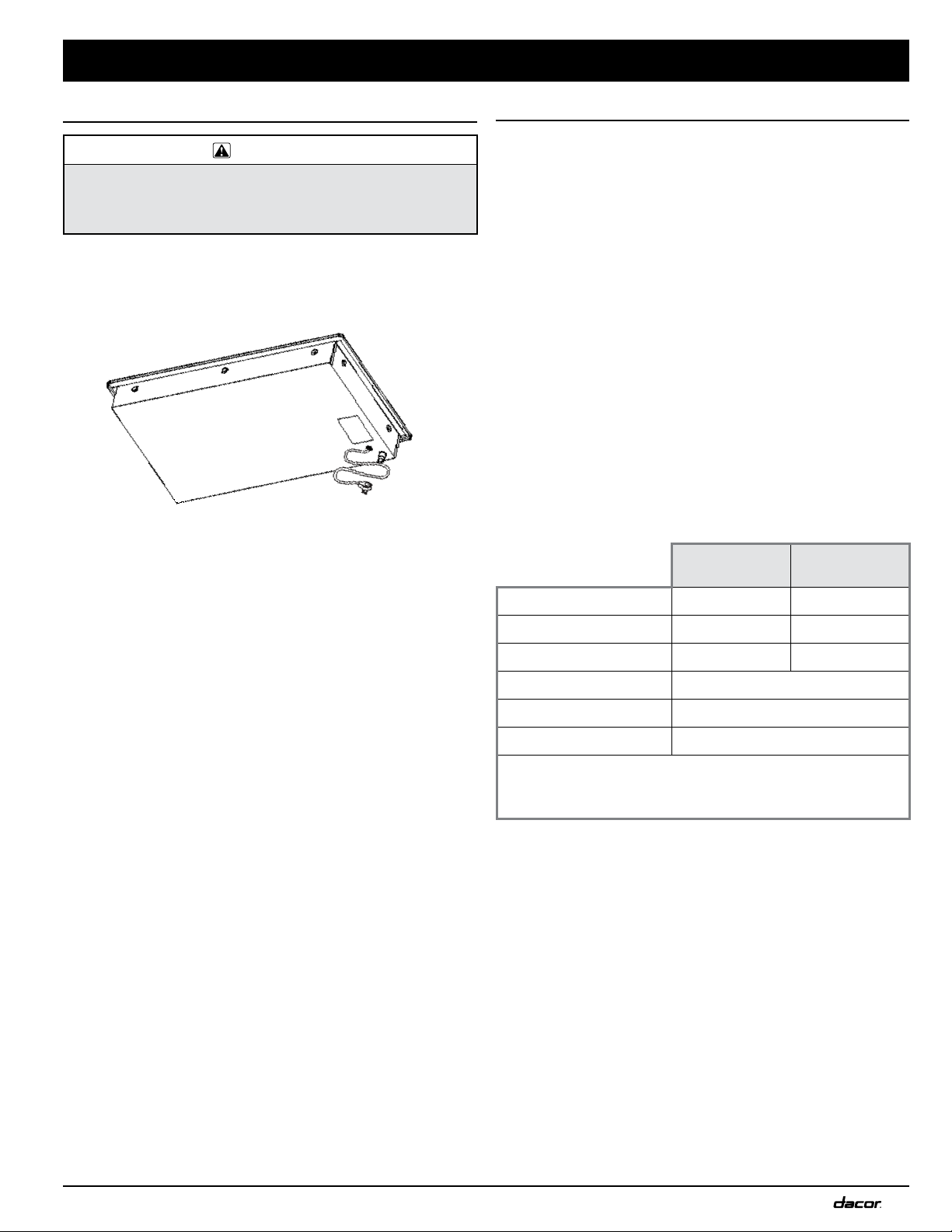
• A 42” power cord with a 3-prong, grounding plug is attached
to the chassis’ bottom in the right-rear corner. You must insert
the plug in a dedicated, grounded 3-prong electrical outlet
installed by a licensed electrician.
HCT305G/-365G (bottom)
• The electrical installation, including minimum-supply wire size
and grounding, must be done according to National Electric
Code ANSI/NFPA 70* and local codes and ordinances. You may
obtain a copy of this standard from:
National Fire Protection Association
1 Batterymarch Park
Quincy, MA 02269-9101
• The correct voltage, frequency, and amperage must be
supplied to the electrical outlet according to the product
data label on the chassis bottom. (See the Gas/Electrical
Requirements table on this page.)
• Position the electrical outlet so the power cord may be easily
disconnected if the unit needs service.
Gas-Supply Requirements
• Verify that the cooktop matches your provided gas service
(natural gas or liquid propane).
• If using the cooktop above 4000 ft. (1219 m) elevation, ensure
it is equipped for high-altitude operation. (Such units have
an “H” at the end of their model number on the product-data
label; see the Product Data Label section.)
• Units equipped for liquid-propane have “LP” in the model number on the product-data label.
• Check local building codes for the proper installation method.
If no local code exists, follow National Fuel Gas Code ANSI
Z223.1/NFPA 54.
• An external, manual shut-off valve must be installed between
the gas-supply line and the cooktop so gas to the cooktop can
be shut on/off.
• Use only the provided regulator, which must be installed
between the cooktop gas inlet and the gas shut-off valve.
• Because the regulator inlet accommodates a 3/4” gas line, and
the cooktop inlet is a 1/2” male NPT fitting, a 3/4”-to-1/2” reducer is included with the cooktop. (See HCT305G/-365G at left.)
Gas/Electrical Requirements*
HCT305G_NG
HCT365G_NG
Gas Type Natural gas Liquid propane
Manifold Pressure 5” Water column 10” Water column
Min. Gas-Supply Pressure** 6” Water column 11” Water column
Max. Gas-Supply Pressure 1/2 psi
Total Connected Load 0.25 Amp. (30 Watts)
Circuit Requirement 120 Vac, 60 Hz, 15 Amp.
*This gas/electrical data is for reference only. If this data conflicts with the
product-data label, use the data on the label.
**The gas-supply pressure for testing the regulator setting shall be at least
1-in. water column (249 Pa) above the specified manifold pressure.
HCT305G_LP
HCT365G_LP
3
Page 6

Installation Specifications
Product Dimensions All tolerances: ±1/16” (±1.6 mm) unless otherwise noted.
HCT305G and HCT365G
W x H x D Dimensions
HCT305G/-365G Utility Locations
WARNING
Observe applicable codes and ordinances during planning/
installation. Contact your local building authority for details.
Cooktop/Chassis Overhang Dimensions
Model
HCT305G 30” (76.2 cm) 27 5/16” (69.4 cm)
HCT365G 36” (91.4 cm) 33 5/16” (84.6 cm)
HCT305G/-365G Utility Dimensions
4
A (width) B (width)
Page 7

13” max.
3
(33.0 cm)
3
This specification does not apply for cabinets located
greater than a horizontal distance of 5 1/2” (14.0 cm) from
edge of cooktop. Allow 6 7/8” (17.5 cm) from cutout edge.
A
1 5/8” min.
(4.1 cm)
Combustible
surface to rear
30” min.
1, 2
(76.2 cm)
See cutout
dimensions
See cutout
dimensions
2
If installing with an overhead range hood, check the hood
specifications for minimum required clearances.
1
Distance to combustible surfaces measured from cooking
surface (top of cooktop grate).
18” min.
1, 3
(45.7 cm)
* Allows for clearance between hold down brackets
Installation Specifications
Cabinet and Countertop Layout
WARNING
• To reduce risk of burn injury from reaching over a hot appliance, do not
hang cabinets above the cooktop.
• Failure to meet or exceed the max/min dimensions and clearances in
this manual may cause a fire hazard.
• Follow the countertop manufacturer’s instructions regarding minimum
corner radius, use of heat-reflective tape, corner reinforcement, etc.
B
1/4” (6 mm)
mimimum clearance
to combustible
surfaces
• Carefully check the cooktop location site. For best performance, the cooktop should be near drafts from open doors/
windows, and heating/air-conditioning vents.
• This appliance is to be used with a suitable vent hood or
approved Dacor downdraft vent.
Minimum Clearances Around the Cooktop
This section consists of illustrations/notes/tables for clearance
allowances. All tolerances: +1/16” -0” unless otherwise noted.
• Allow at least ¼” (6 mm) clearance from the bottom of the
cooktop chassis to all combustible surfaces (incl. the top edge
of a drawer).
Under-Cabinet Clearances
Model (B) Minimum
HCT305G 29 1/4” (74.3 cm)
HCT365G 35 1/4” (89.5 cm)
• The gas-supply piping, gas shut-off valve, and the electrical
outlet must be located so as not to impede cooktop installation. If installing an appliance below the cooktop, allow for
gas/electrical routing behind it.
Installation must allow:
• access to the gas shut-off valve and regulator
• access to the electrical outlet; the 42” (106.7 cm) power cord
must be able to reach its intended outlet.
• access to the cooktop bottom for service/inspection.
• space in the cabinet for the cooktop hold-down brackets.
Do not install a fixed shelf below the cooktop.
Downdraft Compatibility
If installing the cooktop with a downdraft, use only the approved
Dacor downdraft model numbers below.
Model (A) Minimum (A) Recommended
HCT305G 30” (76.2 cm) 36” (91.4 cm)
HCT365G 36” (91.4 cm) 42” (106.7 cm)
Cooktop Model Approved Downdraft
HCT305G ERV3015
HCT365G ERV3615
5
Page 8

Stiffener
Cabinet face
Countertop
Floor
3/8” min. (1.0 cm)
behind downdraft
to clear stiffener
3/8” min. (1.0 cm)
clearance required
behind cutout
ERVxx15 Downdraft
Check downdraft
dimensions/specifications
to determine proper fit
RNCT Series Cooktop
Installation Specifications
Cutout Dimensions All tolerances: ±1/16” (±1.6 mm) unless otherwise noted.
Rear
wall
Vertical
combustible
surface
4 1/4” (10.8 cm) min.
from mounting surface to
combustibles below
cooktop chassis
F
C
D
F
1 5/8” min.
(4.1 cm)
Configuration (C) Minimum (D) (E) (F) Minimum
HCT305G (no downdraft) 3 1/4” (8.3 cm) 19 5/8” (49.9 cm)
HCT305G (ERV3015 downdraft) 3/8” (1.0 cm) 22 3/4” (57.8 cm)
HCT365G (no downdraft) 3 1/4” (8.3 cm) 19 5/8” (49.9 cm)
HCT365G (ERV3615 downdraft) 3/8” (1.0 cm) 22 3/4” (57.8 cm)
Minimum distance to combustible side
wall above countertop (both sides)
Cooktop with Downdraft:
ERV Series
HCT
E
27 5/8” (70.2 cm)
6 7/8” (17.5 cm)
33 5/8” (85.4 cm)
6
Page 9

Installation Instructions
Verifying Package Contents
• Hold-down brackets (2)
• Grates (3)
• Burner sets (5)
• Gas-pressure regulator (1)
• Stainless-steel cleaner (1; stainless-steel models only)
If parts are missing, contact Dacor Customer Assurance. (See If
You Need Help…, inside cover.)
Installing the Cooktop
WARNING
• Before proceeding, verify that the power supply meets the specifications on Page 3.
• To avoid damaging the gas-pressure regulator, install it only after
the cooktop is mounted in its final position.
IMPORTANT
• Do not overtighten the hold-down bracket bolts, as doing so may
lead the dual gas burners to malfunction.
• Do not seal the cooktop to the countertop with hardening compound
or caulk. The cooktop must be removable for servicing. The customer
is financially responsible for removal of sealant to service the unit.
1. (If a downdraft will be used) Install the downdraft according
to the downdraft installation instructions.
2. Lower the cooktop through the cutout and center it.
3. With the two provided hold-down brackets, secure the
cooktop to the countertop as shown.
Hold-down
bracket
mounting holes
(left and right)
Connecting the Gas Line
WARNING
• First, ensure the gas supply meets specifications (inside cover).
• Install the included gas regulator before you install/use the cooktop.
• Ensure the regulator arrow points toward the cooktop.
• Do not overtighten the gas connections/fittings.
• Do not use Teflon tape or plumber’s putty on flexible gas-line con
nections.
• Before use, test the gas lines for leaks as instructed. (Do not use a
flame to check for leaks.)
• The gas-supply pressure to the regulator must never exceed ½ psi
(3.5 kPa).
• Disconnect he cooktop and shut-off valve from the gas supply for
pressure testing over ½ psi (3.5 kPa).
• The shut-off valve to the cooktop must be closed to isolate the
cooktop from the gas supply during gas-supply piping-system pres
sure testing ≤ psi (3.5 kPa).
• For liquid propane installations, the LP tank must have its own highpressure regulator besides the Dacor-supplied regulator.
1. Attach the gas-pressure regulator (included) to the gas inlet
on the chassis bottom (see graphic at left).
NOTE
• In tight spaces, you can install the regulator anywhere between the
cooktop and gas-supply/shut-off valve.
• For best results, attach the regulator as close as possible to the
cooktop (to minimize gas-pressure loss).
2. Connect the regulator to the gas-supply/shut-off valve with a
minimum 1/2” flexible gas line (not included).
3. Check for gas leaks:
a. Turn all cooktop control valves OFF.
b. With a soap-and-water solution or gas-leak detector,
check all lines and connections for gas leaks. (Ensure the
gas-supply/shut-off valve is ON.)
c. Turn the gas supply/shut-off valve OFF.
-
-
Power cord
Gas inlet
7
Page 10

Installation Instructions
Assembling the Burners
WARNING
• Never operate the cooktop with burner parts removed.
• All burner air-mixture settings are done at the factory; do not try to
adjust these settings..
Remove the burner heads, rings, caps, and grates from their
packaging.
1. Assemble the burners as shown on this page:
a. Gather same-size components (i.e., large cap with large
ring, etc).
b. Center, and turn each piece until it seats properly. (The
burners will not function properly unless all components
are properly seated.)
NOTE
The burner base is permanently attached to the unit; it cannot be
adjusted/removed.
Burner cap
(bottom)
Igniter goes
through hole
Inner burner cap
(bottom)
Outer burner cap
Burner ring
Line up
indentations
with pins
Burner base
SimmerSear™ Burner Assembly
Burner ring
Burner head
Burner base
Igniter
CAUTION: Igniter
tip is sharp
Standard Burner Assembly
8
Page 11

Installation Instructions
Placing the Grates
When a grate is correctly installed, the tips of the four longest fingers center over the corresponding burner.
♦ Use the grate notches to place and orient the grates.
– The notches beneath the grates fit the cooktop rear.
– The notches on the grate sides fit the cooktop sides.
– Gently set the grate legs in their corresponding dimples in the cooktop.
9
Page 12

Installation Instructions
Verifying Proper Function
Perform this procedure for all cooktop burners.
WARNING
The cooktop must always be properly grounded when electrical
power is applied.
1. Turn off power to the electrical outlet at the circuit breaker or
fuse box.
2. Close the gas-supply valve.
3. Turn off all cooktop burner controls.
4. Plug in the power cord.
5. Turn on power to the electrical outlet at the circuit breaker or
fuse box.
6. Press-turn a burner-control knob slowly counterclockwise to
the flame icon (high flame).
a. Verify that the corresponding burner igniter sparks (rapid
tick-tick) and the burner indicator comes on.
b. Turn off the burner.
7. Turn the gas-supply valve ON.
8. Verify that the gas flame ignites on all burners:
a. Press-turn a control knob to the flame icon.
NOTE
SimmerSearTM burner: Turn the control knob to the simmer setting, and ensure the low-level flame can be adjusted and the
burner indicator illuminates.
Troubleshooting
If the cooktop fails to function properly, review these steps:
• Verify that the cooktop receives power/gas.
• Verify that the cooktop is plugged in and power is turned on at
the power source.
• Verify that all the burners are correctly assembled/seated.
• If the burner sparks after ignition, have a licensed electrician
check the electrical outlet for correct grounding or reversed
polarity.
• Repeat Step 8 of the Verification procedure.
If the appliance still does not work, do not try to repair the appliance, but contact Dacor Customer Assurance: 833-353-5483.
Have the model and serial numbers available. (See the inside
cover for this information.)
Dacor is not responsible for the cost of correcting problems
caused by faulty installation.
NOTE
• If ignition does not occur within 4 seconds, turn the knob OFF,
wait 5 minutes (for gas to dissipate), then repeat Step 8a.
• A proper flame burns steadily with a sharp, blue inner cone. The
Smart Flame™ feature reduces the flame under the grate fingers to lengthen grate life.
b. After ignition, turn the knob clockwise to the OFF position.
10
Page 13

Installation Instructions
Installer Checklist
IMPORTANT
Though the installer should complete this checklist to ensure proper
installation/function, the homeowner is ultimately responsible for the
cooktop’s proper installation.
□ Is the cooktop’s electrical outlet grounded/located as
instructed and per applicable codes? (Pg. 3.)
□ Is gas service to the cooktop located/installed per as instruct-
ed and per applicable codes? (Pg. 3.)
□ Was the gas-supply inlet pressure verified to be within the
maximums specified in this manual? (Pg. 3.)
□ Is the cooktop secured with the provided hold-down brack-
ets? (Pg. 8.)
□ Is the cooktop connected to the gas supply as instructed and
per applicable codes? Was the gas supply checked for leaks?
(Pg. 7.)
□ Are the burners/grates properly assembled? (Pg. 9.)
□ Was proper function verified? (Pg. 11.)
□ Has the warranty been activated on-line or the warranty card
filled out completely and mailed?
Wiring Diagram
WARNING
Because miswiring can cause malfunction and dangerous operation, label all wires before disconnection when servicing controls, then verify
proper function after service.
HCT305G and HCT365G
11
Page 14

Notes
Page 15

Notes
Page 16

Dacor ● 14425 Clark Avenue, City of Industry, CA 91745 ● Phone: (800) 793-0093 ● Fax: (626) 403-3130 ● www.dacor.com
 Loading...