

Page 1

ERWD, EWD, IWD, MRWD, MWDV, MWDH,
23 3/8"
(594 mm)
Chassis
Drawer open
5/64"
(2mm)
23 13/16”
(605 mm)
B
C
A
10 1/8”
(257 mm)
3 7/16"
(87 mm)
EWD
3 1/4"
(83 mm)
MWDH/V
1"
(25 mm)
3 1/2"
(89 mm)
MRWD30B
(only)
All other MRWD
series
ERWD
1 1/8"
(29 mm)
1 7/16"
(37 mm)
1"
(25 mm)
PWD
2 1/4"
(57 mm)
1"
(25 mm)
1"
(25 mm)
10"
(254 mm)
9"
(229 mm)
1/2" (13 mm)
1/2" (13 mm)
Chassis without
drawer inserted
Mounting
hole 9 places
40” (1016 mm)
3 prong 120 Vac
power cord
Document # PG02-002 Revised 04/01/10 Page 1/3
Product tolerances: ±1/16” (±1.6 mm) unless otherwise stated
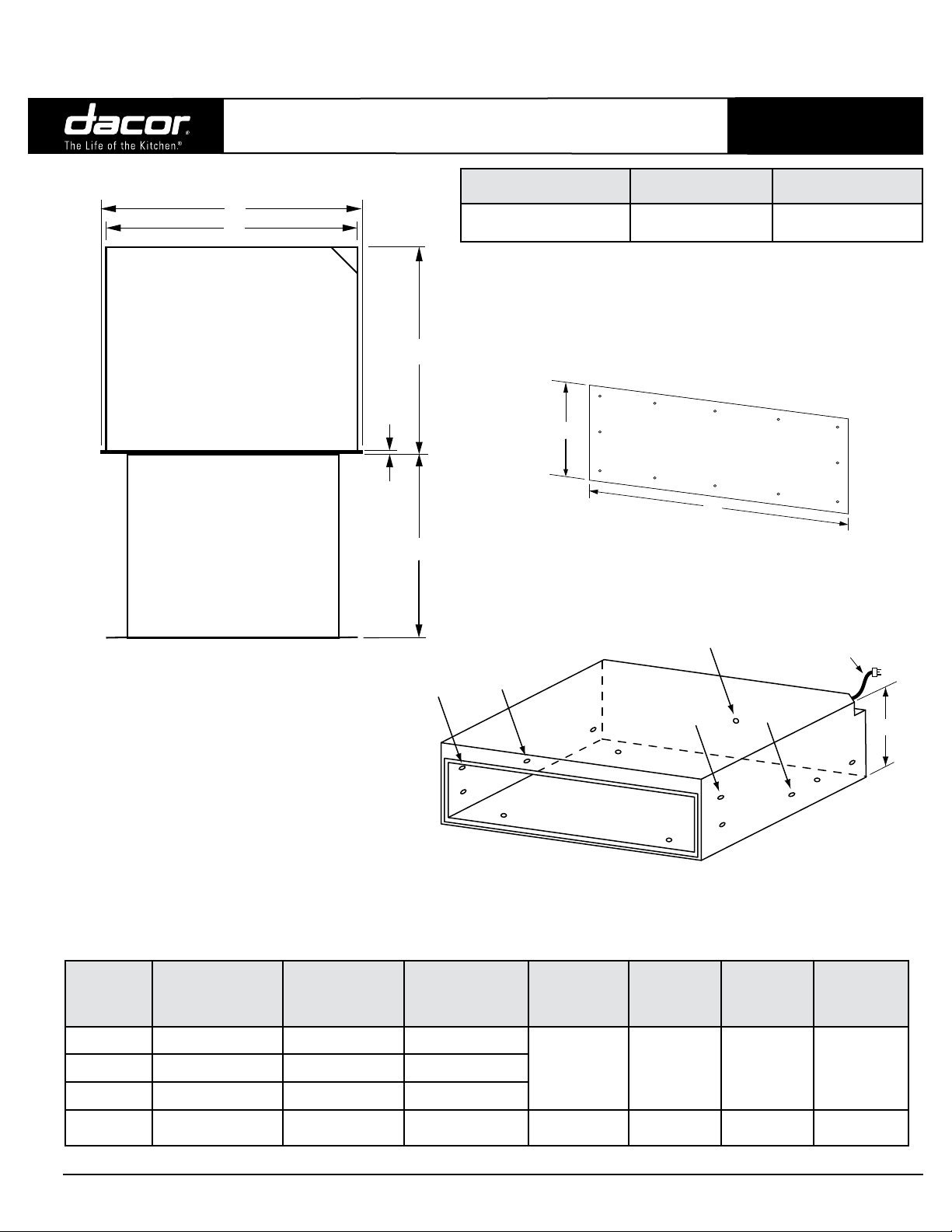
HANDLE DIMENSIONS - SIDE VIEW
OWD and PWD
24”, 27”, 30”, 36”,
Wide Warming Drawers
Electrical Circuit Required Total Connected Load
120 Vac, 60 Hz, 15 Amp.
grounded, dedicated circuit
DRAWER FACE DIMENSIONS
(MWD SERIES SHOWN)
4.0 Amp.
@ 120 Vac, 60 Hz.
PLANNING
GUIDE
Minimum Ambient
Operating Temperature
32°F (0°C)
For PWD series models:
Specications subject to change without notice.
Install all appliances according to accompanying installation instructions.
OVERALL DIMENSIONS - TOP VIEW
(EWD SERIES SHOWN)
The Dacor color palette has been developed and implemented
throughout our product offerings in order to provide designers
and customers with a coordinating suite of products. All of our
Dacor Preference products compliment the design aesthetic
of today's kitchens as well as one another. Due to the inherent
nature of color rendition, the variation of materials used to
assemble these handcrafted products and manufacturing
production tolerances, variation based upon ambient and natural
lighting conditions as well as surrounding surface color and
texture may cause noticeable variation in saturation. These
Dacor products are intended to coordinate with one another and
noticeable differentiation may be apparent if units are installed
directly adjacent to one another.
CHASSIS DIMENSIONS
Model
ERWD30 30” (762 mm) 29 5/8” (752 mm) 28 1/4” (718 mm)
EWD24 24” (610 mm) 23 5/8” (600 mm) 22 1/4” (565 mm)
EWD27 27” (686 mm) 26 5/8” (676 mm) 25 1/4” (641 mm)
EWD30 30” (762 mm) 29 5/8” (752 mm) 28 1/4” (718 mm)
EWD36 36” (914 mm) 35 5/8” (905 mm) 34 1/4” (870 mm)
MRWD27 26 3/4” (679 mm) 26 5/8” (676 mm) 25 1/4” (641 mm)
MRWD30 29 3/4” (756 mm) 29 5/8” (752 mm) 28 1/4” (718 mm)
MWDH27 27” (686 mm) 26 5/8” (676 mm) 25 1/4” (641 mm)
MWDH30 30” (762 mm) 29 5/8” (752 mm) 28 1/4” (718 mm)
MWDV27 27” (686 mm) 26 5/8” (676 mm) 25 1/4” (641 mm)
MWDV30 30” (762 mm) 29 5/8” (752 mm) 28 1/4” (718 mm)
PWD27 27” (686 mm) 26 5/8” (676 mm) 25 1/4” (641 mm)
PWD30 30” (762 mm) 29 5/8” (752 mm) 28 1/4” (718 mm)
(A) Drawer Face
Width
WARMING DRAWER OVERALL DIMENSIONS
www.Dacor.com Phone: (800) 793-0093
(B) Chassis Face
Width
(C) Chassis
Width
2.1
Page 2
ERWD, EWD, IWD, MRWD, MWDV, MWDH,
D
A
Chassis
Drawer open
F
E
5/16”
(8 mm)
B
C
40" (1016 mm)
3 prong
120 Vac power cord
Chassis without
drawer installed
Mounting hole,
** = OWD24 mounting holes
**
**
**
**
9 places
G
Document # PG02-002 Revised 04/01/10 Page 2/3
Product tolerances: ±1/16” (±1.6 mm) unless otherwise stated
OWD and PWD
24”, 27”, 30”, 36”,
Wide Warming Drawers
Electrical Circuit Required Total Connected Load
120 Vac, 60 Hz, 15 Amp.
grounded, dedicated circuit
4.0 Amp.
@ 120 Vac, 60 Hz.
PLANNING
GUIDE
Minimum Ambient
Operating Temperature
32°F (0°C)
DRAWER FACE DIMENSIONS
(IWD/OWD SERIES SHOWN)
OVERALL DIMENSIONS - IWD/OWD SERIES
TOP VIEW
CHASSIS DIMENSIONS
(IWD/OWD SHOWN)
Model
IWD24 22 5/16” (567 mm) 22 1/4” (565 mm) 22 3/8” (568 mm)
IWD27 25 5/16” (643 mm) 25 1/4” (641 mm) 25 3/8” (645 mm)
IWD30 28 5/16” (719 mm) 28 1/4” (718 mm) 28 3/8” (721 mm)
OWD24 22 1/2” (571 mm) 22 1/2” (571 mm) 22 1/2” (571 mm)
(A) Dimension
Drawer Face Width
(B) Dimension
Chassis Width
(C) Dimension
Chassis Face
Width
(D)
Dimension
Drawer Face
Height
8 15/16”
(227 mm)
11 7/8”
(302 mm)
(E)
Dimension
Chassis
Depth
23 3/8”
(594 mm)
20”
(508 mm)
(F)
Dimension
Drawer
Depth
23 13/16”
(605 mm)
18”
(457 mm)
(G)
Dimension
Chassis
Height
9 1/16”
(230 mm)
11 7/8”
(302 mm)
Specications subject to change without notice.
Install all appliances according to accompanying installation instructions.
www.Dacor.com Phone: (800) 793-0093
2.2
Page 3

ERWD, EWD, IWD, MRWD, MWDV, MWDH,
Warming
drawer
Cooktop
1 1/2" (38 mm)
Typical countertop
3/4” Min.*
(19 mm)
120 Vac
electrical
outlet
A
36" Typ.
B
C
A
Warming
drawer
Warming
drawer
B
3/4" Min.*
(19 mm)
D
3/4" Min.*
(19 mm)
36" Typ.
(914 mm)
120 Vac
electrical
outlet
C
C
27"/30"/36" Dacor
single wall oven
Warming
drawer
Warming
drawer
Toe kick
D
C
C
D
120 Vac
elect.
120 Vac
elect.
A
3/4" Min.*
(19 mm)
Document # PG02-002 Revised 04/01/10 Page 3/3
Cabinet/countertop tolerances: +1/16” (+1.6 mm) -0 unless otherwise stated
OWD and PWD
24”, 27”, 30”, 36”
Wide Warming Drawers
PLANNING
GUIDE
WARNING
Observe all governing codes and ordinances •
during planning and installation. Contact your
local building department for further information.
This appliance must be installed in accordance •
with the accompanying installation instructions.
Mounting platform must be 3/4" (19 mm) thick
and support 100 lbs.
Model (A) Cutout Width
ERWD30 28 1/2” (724 mm) 30 1/4” (768 mm)* 9 1/8” (232 mm) 1 1/4” (32 mm)*
EWD24 22 1/2” (572 mm) 24 1/4” (616 mm)* 9 1/8” (232 mm) 1 1/4” (32 mm)*
EWD27 25 1/2” (648 mm) 27 1/4” (692 mm)* 9 1/8” (232 mm) 1 1/4” (32 mm)*
EWD30 28 1/2” (724 mm) 30 1/4” (768 mm)* 9 1/8” (232 mm) 1 1/4” (32 mm)*
EWD36**** 34 1/2” (876 mm) 36 1/4” (921 mm)* 9 1/8” (232 mm) NA
IWD24**** 22 1/2” (572 mm) ** 9 1/8” (232 mm) NA
IWD27**** 25 1/2” (648 mm) ** 9 1/8” (232 mm) NA
IWD30**** 28 1/2” (724 mm) ** 9 1/8” (232 mm) NA
MRWD27 25 1/2” (648 mm) 27” (686 mm)* 9 1/8” (232 mm) 1 1/4” (32 mm)*
MRWD30 28 1/2” (724 mm) 30” (762 mm)* 9 1/8” (232 mm) 1 1/4” (32 mm)*
MWDH27 25 1/2” (648 mm) 27 1/4” (692 mm)* 9 1/8” (232 mm) 1 1/4” (32 mm)*
MWDH30 28 1/2” (724 mm) 30 1/4” (768 mm)* 9 1/8” (232 mm) 1 1/4” (32 mm)*
MWDV27 25 1/2” (648 mm) 27 1/4” (692 mm)* 9 1/8” (232 mm) 1 1/4” (32 mm)*
MWDV30 28 1/2” (724 mm) 30 1/4” (768 mm)* 9 1/8” (232 mm) 1 1/4” (32 mm)*
OWD24***** 22 5/8” (575 mm) 24 1/4” (616 mm)*** 11 15/16” (303 mm) NA 20 1/8” (511 mm)
PWD27 25 1/2” (648 mm) 27 1/4” (692 mm)* 9 1/8” (232 mm) 1 1/4” (32 mm)*
PWD30 28 1/2” (724 mm) 30 1/4” (768 mm)* 9 1/8” (232 mm) 1 1/4” (32 mm)*
* Bare minimum spacing to allow for ventilation and avoid scraping on EWD, MW and PWD series models.
** On IWD series models or OWD24 without the optional front panel kit: The chassis and the drawer faceplate are smaller than the cutout.
The custom front panel mounts to the drawer faceplate. The height and width of the custom front panel must exceed the appropriate cutout
dimensions (A and C above) to cover the hole. Allow 1/4" minimum additional space on the top, bottom and sides from the
custom front panel edge to prevent scraping against adjacent doors, drawers and the countertop.
Specications subject to change without notice.
Install all appliances according to accompanying installation instructions.
*** OWD24 with optional factory front panel kit only. Bare minimum spacing shown to avoid scraping. Gap above and below
cutout is 3/4” minimum. See ** above for OWD24 with custom front panel.
**** This model cannot be installed above or below another warming drawer (any type).
***** Model OWD24 cannot be installed above, below or adjacent to a wall oven or warming drawer (any type).
(B) Min. Width to
Adjacent Doors/
Drawers
(C) Cutout Height
(D) Min. Vertical Gap
Between Cutouts
www.Dacor.com Phone: (800) 793-0093
Min. Cutout Depth
24” (610 mm)
24” (610 mm)
2.3
 Loading...