

Page 1

The Life of the Kitchen?
° USE
AND CARE MANUAL
EPICURE ® RANGE
For Use WithModels ER3OD,ER3ODSR,ER3OD-C
Table of Contents
Important Safety Instructions ............................................. 1-4
Getting To Know Your Range ............................................ 4-6
Setting Up Your Range ..................................................... 7-9
Operating the Cooktop ................................................ 10-11
Operating the Oven .................................................... 12-21
Cooking Tips ................................................................... 22
Cleaning and Maintenance .......................................... 23-28
Replacement Parts and Accessories ................................... 29
Before You Call for Service ........................................... 30-31
Warranty and Service ...................................................... 32
Warranty Card .................................................... Back Cover
Pa_ No. 102188 Rev. D
Page 2
To Our Valued Customer:
Congratulations on your purchase of the very latest in Dacor _ products! Our unique combination of features, style and
performance make us The Life of the Kitchen _, and a great addition to your home.
In order to familiarize yourself with the controls, functions, and full potential of your new Distinctive Appliance, we
suggest that you thoroughly read this use and care manual, beginning with the Important Safety Instructions
section.
All Dacor appliances are designed and manufactured with quality and pride, while working within the framework of our
company value. Should you ever experience a problem with your product, please first check the Before You Call for
Service section of this manual for guidance. It provides useful suggestions and remedies prior to calling for service.
Valuable customer input helps us to continuously improve our products and services, so please feel free to contact
our Customer Service Team for assistance with any of your product support needs,
Dacor Customer Service Team
1440 Bridge Gate Drive
Diamond Bar, CA 91765
Telephone:
Fax:
Hours of Operation:
Web Site:
Thank you for choosing Dacor for your home. We are a company built by families for families and we are dedicated
to serving yours. We are confident that your new Dacor product will deliver a high level of performance and
enjoyment for many years to come.
Sincerely,
(800) 793-0093
(626) 403-3130
Monday through Friday
6:00 A.M. to 5:00 PM. Pacific Time
www.Dacor.com
The Dacor Customer Service Team
© 2007 Dacor, all _i._.,_
Page 3
INSTALLER: LEAVE THIS GUIDE WITH THE APPLIANCE.
CUSTOMER: READ THIS USE AND CARE MANUAL
COMPLETELY BEFORE USING THIS APPLIANCE. SAVE IT
FOR FUTURE REFERENCE. IT CONTAINS IMPORTANT USE
AND CARE INFORMATION. KEEP YOUR SALES RECEIPT OR
CANCELED CHECK IN A SAFE PLACE. PROOF OF ORIGINAL
PURCHASE DATE IS REQUIRED FOR WARRANTY SERVICE.
For warranty and service information, see page 32.
If you have any questions (other than warranty questions), call:
Dacor Customer Service
1-800-793-0093 (U.S.A. and Canada)
Monday -- Friday 6:00 A.M.to 5:00 P.M.Pacific Time
Web site: www.Dacor.com
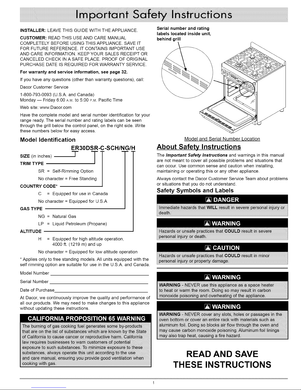
Have the complete model and serial number identification for your
range ready. The serial number and rating labels can be seen
through the grill below the control panel, on the right side. Write
these numbers below for easy access.
Model Identification
ER30DSR-C-SCH/NG/H
SIZE (in inches) T T
TRIM TYPE
SR = Self-Rimming Option
No character = Free Standing
COUNTRY CODE*
C = Equipped for use in Canada
No character = Equipped for U.S.A
GAS TYPE
NG = Natural Gas
LP = Liquid Petroleum (Propane)
ALTITUDE
H
= Equipped for high altitude operation,
4000 ft. (1219 m) and up
No character = Equipped for low altitude operation
* Applies only to free standing models. All units equipped with the
self rimming option are suitable for use in the U.S.A. and Canada.
Model Number
Serial Number
Date of Purchase
At Dacor, we continuously improve the quality and performance of
all our products. We may need to make changes to this appliance
without updating these instructions.
Serial number and rating
labels located inside unit,
behind grill
Model and Serial Number Location
About Safety Instructions
The Important Safety Instructions and warnings in this manual
are not meant to cover all possible problems and situations that
can occur. Use common sense and caution when installing,
maintaining or operating this or any other appliance.
Always contact the Dacor Customer Service Team about problems
or situations that you do not understand.
Safety Symbols and Labels
READ AND SAVE
THESE INSTRUCTIONS
Page 4
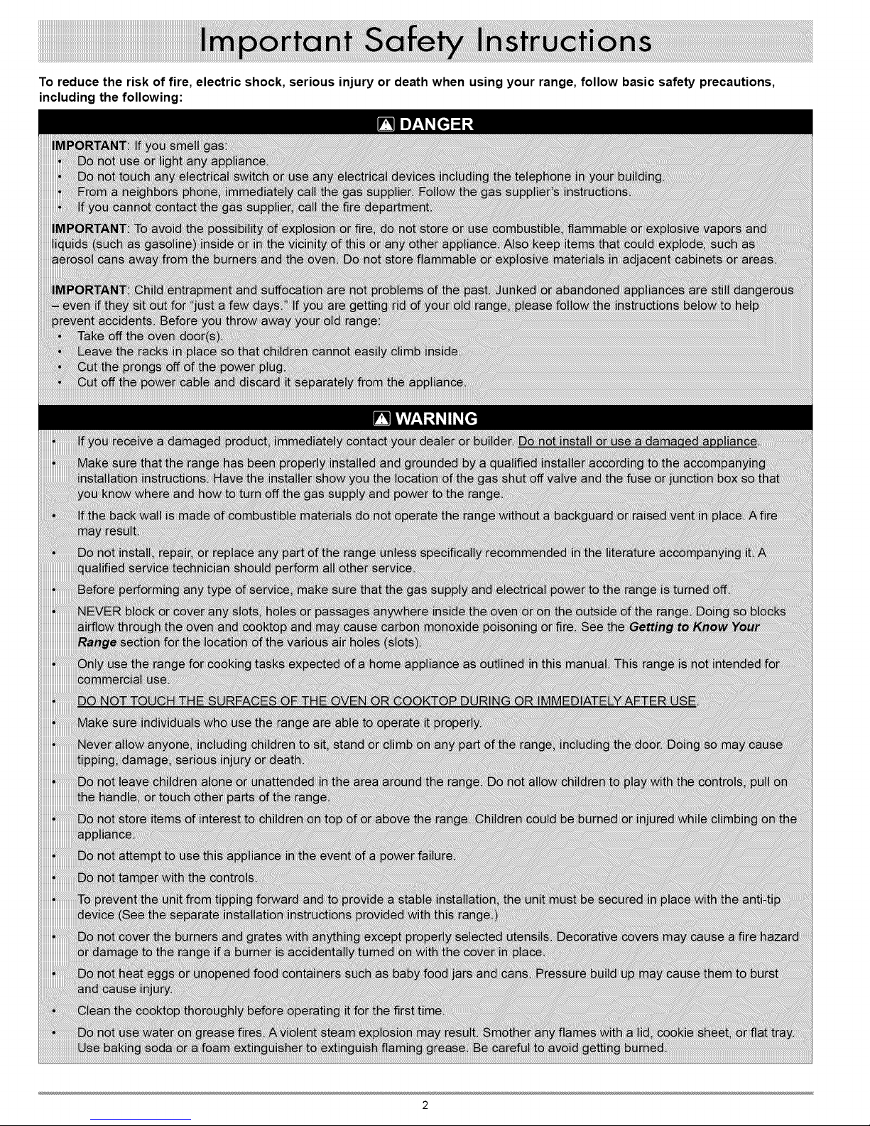
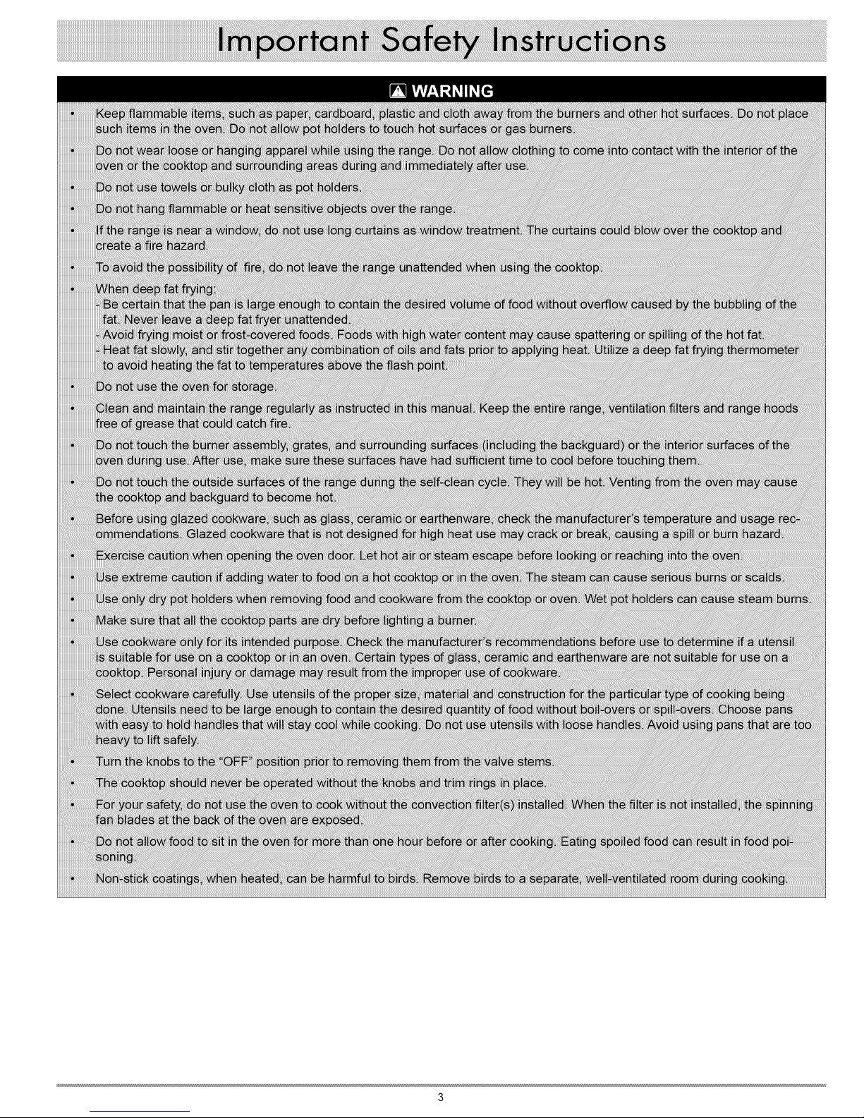
To reduce the risk of fire, electric shock, serious injury or death when using your range, follow basic safety precautions,
including the following:
Page 5
Page 6

Parts of the Oven
CONTROL PANEL: Your oven's control panel consists of a touch
pad and a display. Use the control panel to operate all the oven's
features (sometimes called modes.)
OVEN RACKS: Each oven
comes with chrome-plated
adjustable oven racks. See the Standard 2
table for the number and type GlideRackTM 1
provided with your model. Page
12 describes the difference
between rack types.
RACK SUPPORTS: There are five rack positions inside each
oven chamber. The rack positions are numbered from the bottom
counting up.
MEAT PROBE CONNECTOR: When you use the meat probe,
insert the skewer into the meat and plug the other end into the
connector. See the Meat Probe section on pages 19 - 20 for
proper operation.
OVEN LIGHTS: There are two oven lights inside the oven
chamber so that you can easily see inside. You can use the lights
when the door isopen or to see inside through the window when
the door is closed. The lights turn on or off only when you press
the light key on the control panel. The bulbs are 12 Vac, 20 Watt,
halogen.
DOOR GASKET: The door gasket prevents heat from escaping
when the door isclosed.
SELF-CLEAN LATCH: The self-clean latch automatically locks
the oven door during the self-clean cycle. The door latches for
your safety. There are very high temperatures inside the oven
during the self-clean cycle.
BAKE ELEMENT: The source of bottom heat, attached to the
floor of the oven. The bake element is hidden below the glass
panel on the floor of the oven chamber.
BROIL ELEMENT: The source of top heat, attached to the oven's
ceiling. The broil element is hidden above the glass panel on the
ceiling of the oven chamber.
CONVECTION FAN: The convection fan blows heated air into
the oven chamber during the convection cooking process. The
convection filter covers it.
CONVECTION ELEMENT: The convection element heats the air
that is blown into the oven chamber by the convection fan during
the convection cooking process. The convection filter covers it.
CONVECTION FILTER: The convection filter covers the
convection fan. It helps prevent the transfer of taste from one food
to another when you are cooking a whole meal. It also keeps the
oven cleaner, especially when convection roasting or convection
broiling. In addition, it covers the moving convection fan blades for
safety purposes.
Control Panel Layout
DISPLAY: The control panel display provides various types
of information about the oven, including the current time (once
the clock is set), the current cook settings and the cooking
temperature. The control panel can pivot up for easier access.
NUMBER KEYPAD: When you want to set the temperature, cook
time or the time, use the number keypad.
Page 7
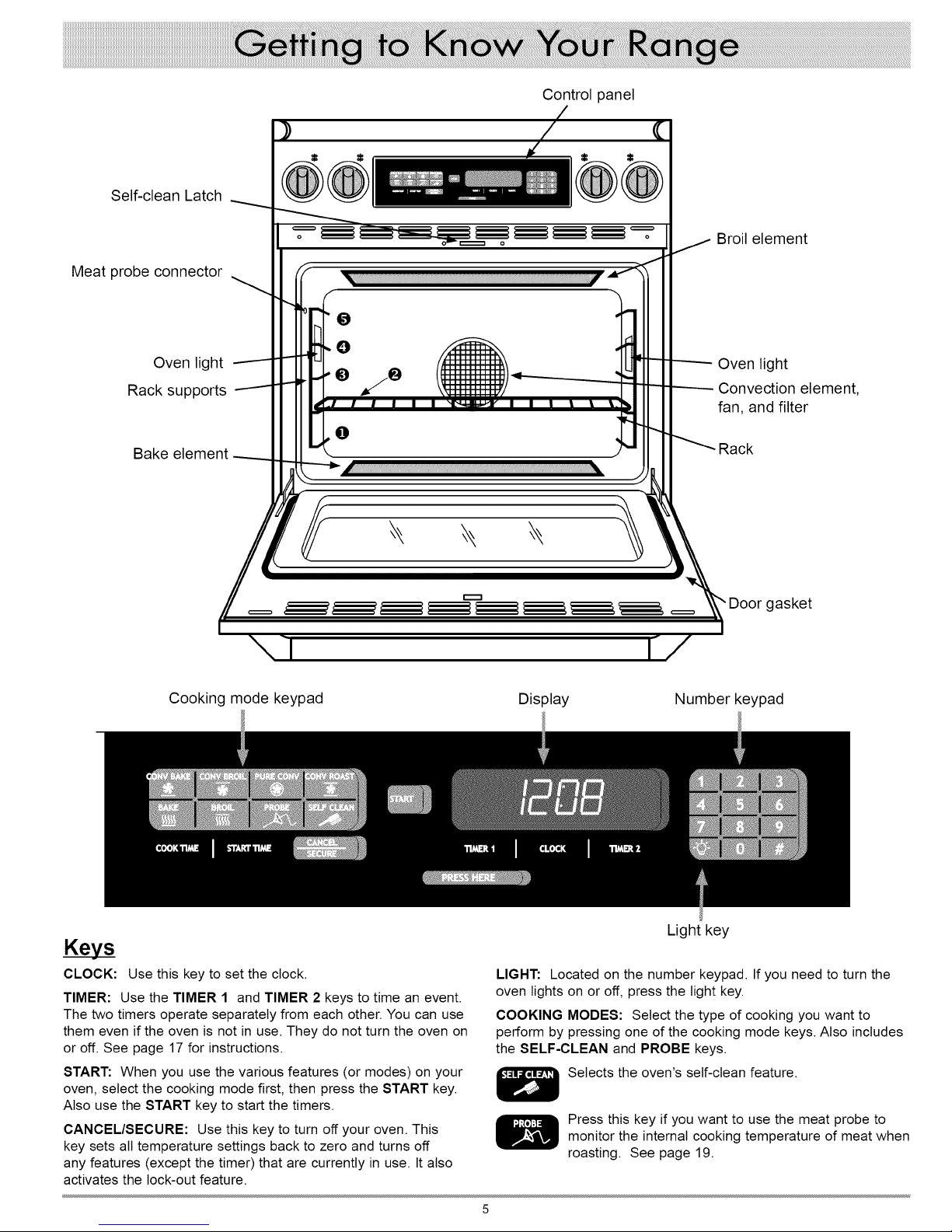
Self-clean Latch
Control panel
Meat probe connector
Oven light
Rack supports
Bake element
o
tJ
Broil element
Oven light
Convection element,
fan, and filter
O
Door gasket
Cooking mode keypad
Keys
CLOCK: Use this key to set the clock.
TIMER: Use the TIMER 1 and TIMER 2 keys to time an event.
The two timers operate separately from each other. You can use
them even if the oven is not in use. They do not turn the oven on
or off. See page 17 for instructions.
START: When you use the various features (or modes) on your
oven, select the cooking mode first, then press the START key.
Also use the START key to start the timers.
CANCEL/SECURE: Use this key to turn off your oven. This
key sets all temperature settings back to zero and turns off
any features (except the timer) that are currently in use. It also
activates the lock-out feature.
Display Number keypad
Light key
LIGHT: Located on the number keypad. If you need to turn the
oven lights on or off, press the light key.
COOKING MODES: Select the type of cooking you want to
perform by pressing one of the cooking mode keys. Also includes
the SELF-CLEAN and PROBE keys.
Selects the oven's self-clean feature.
Press this key if you want to use the meat probe to
monitor the internal cooking temperature of meat when
roasting. See page 19.
Page 8
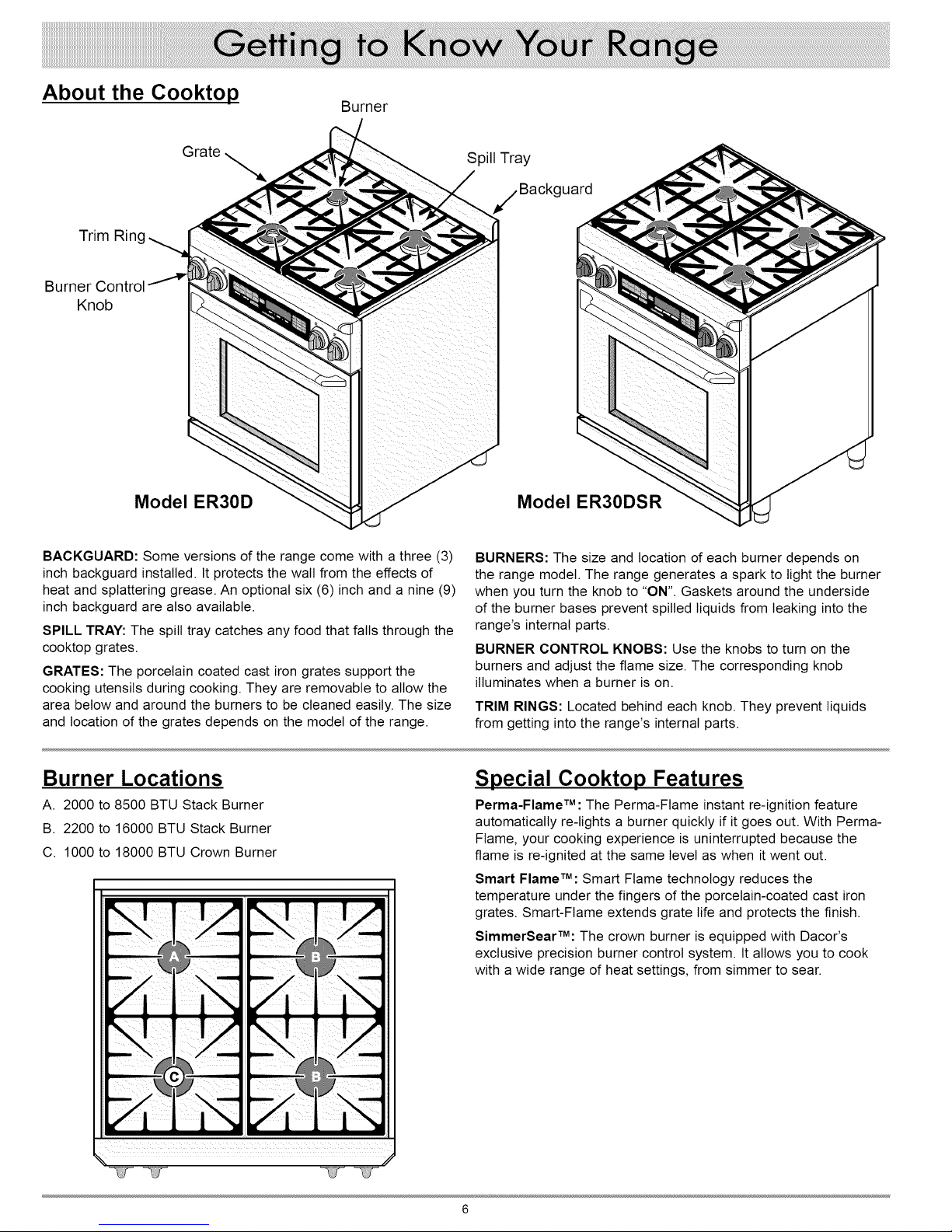
About the Cooktop
Burner
Grate
Trim
Burner
Knob
Model ER30D Model ER30DSR
BACKGUARD: Some versions of the range come with a three (3)
inch backguard installed. It protects the wall from the effects of
heat and splattering grease. An optional six (6) inch and a nine (9)
inch backguard are also available.
SPILL TRAY: The spill tray catches any food that falls through the
cooktop grates.
GRATES: The porcelain coated cast iron grates support the
cooking utensils during cooking. They are removable to allow the
area below and around the burners to be cleaned easily. The size
and location of the grates depends on the model of the range.
Spill Tray
uard
BURNERS: The size and location of each burner depends on
the range model. The range generates a spark to light the burner
when you turn the knob to "ON". Gaskets around the underside
of the burner bases prevent spilled liquids from leaking into the
range's internal parts.
BURNER CONTROL KNOBS: Use the knobs to turn on the
burners and adjust the flame size. The corresponding knob
illuminates when a burner is on.
TRIM RINGS: Located behind each knob. They prevent liquids
from getting into the range's internal parts.
Burner Locations
A. 2000 to 8500 BTU Stack Burner
B. 2200 to 16000 BTU Stack Burner
C. 1000 to 18000 BTU Crown Burner
Special Cooktop Features
Perma-FlameTM: The Perma-Flame instant re-ignition feature
automatically re-lights a burner quickly if it goes out. With Perma-
Flame, your cooking experience is uninterrupted because the
flame is re-ignited at the same level as when it went out.
Smart FlameTM: Smart Flame technology reduces the
temperature under the fingers of the porcelain-coated cast iron
grates. Smart-Flame extends grate life and protects the finish.
SimmerSearTM: The crown burner is equipped with Dacor's
exclusive precision burner control system. It allows you to cook
with a wide range of heat settings, from simmer to sear.
Page 9
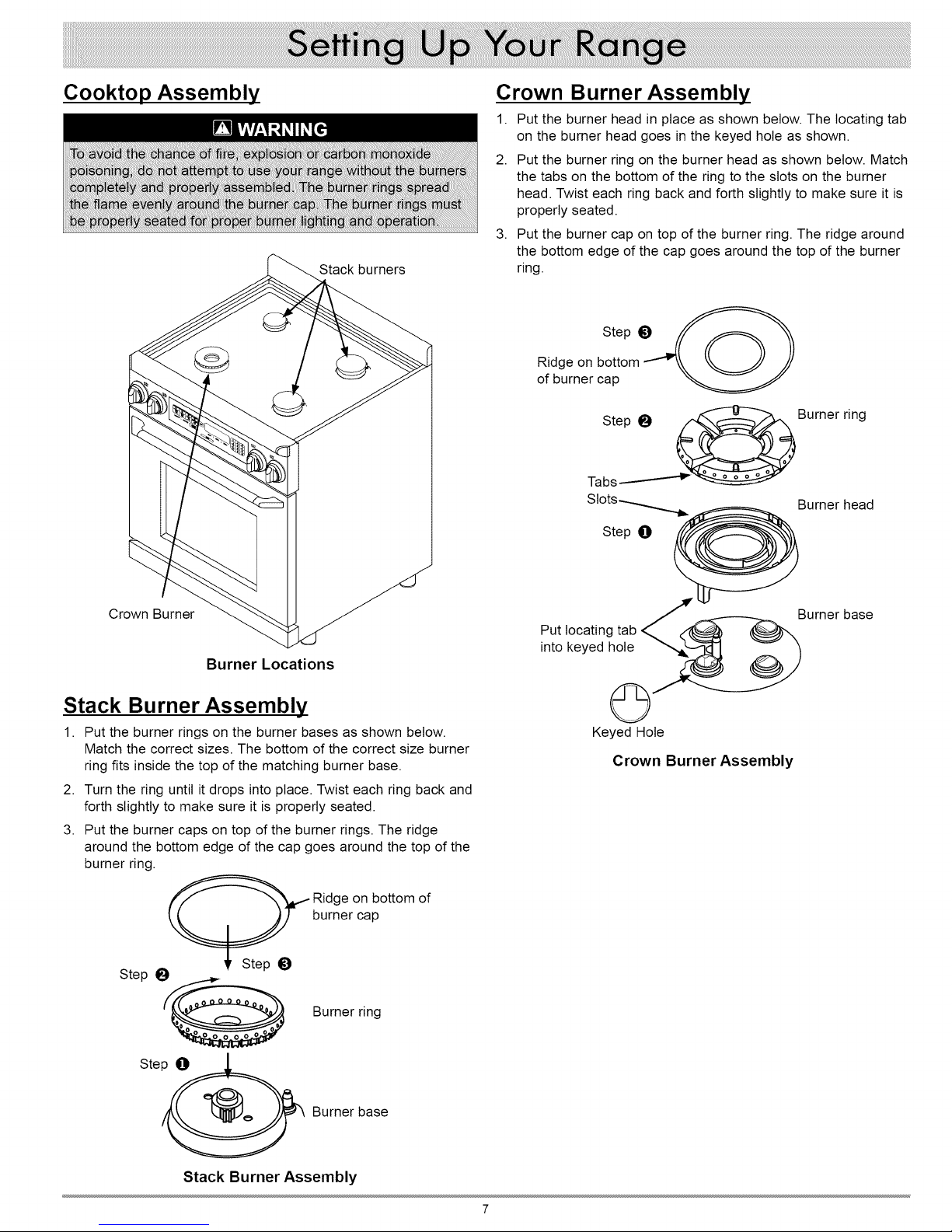
Cooktop Assembly
Stack burners
Crown Burner Assembly
1. Put the burner head in place as shown below. The locating tab
on the burner head goes in the keyed hole as shown.
2. Put the burner ring on the burner head as shown below. Match
the tabs on the bottom of the ring to the slots on the burner
head. Twist each ring back and forth slightly to make sure it is
properly seated.
3. Put the burner cap on top of the burner ring. The ridge around
the bottom edge of the cap goes around the top of the burner
ring.
Step tD
Ridge on bottom -""-" _. _ S
of burner cap
Step 0
Crown Burner
Burner Locations
Stack Burner Assembly
1. Put the burner rings on the burner bases as shown below.
Match the correct sizes. The bottom of the correct size burner
ring fits inside the top of the matching burner base.
2. Turn the ring until it drops into place. Twist each ring back and
forth slightly to make sure it is properly seated.
3. Put the burner caps on top of the burner rings. The ridge
around the bottom edge of the cap goes around the top of the
burner ring.
_ idge on bottom of
Step O
_ Burner ring
_' Step tD
burner cap
Burner base
Put locating tab _
into keyed hole _ 0)9
Keyed Hole
Crown Burner Assembly
Ste_ Burner base
Stack Burner Assembly
Page 10
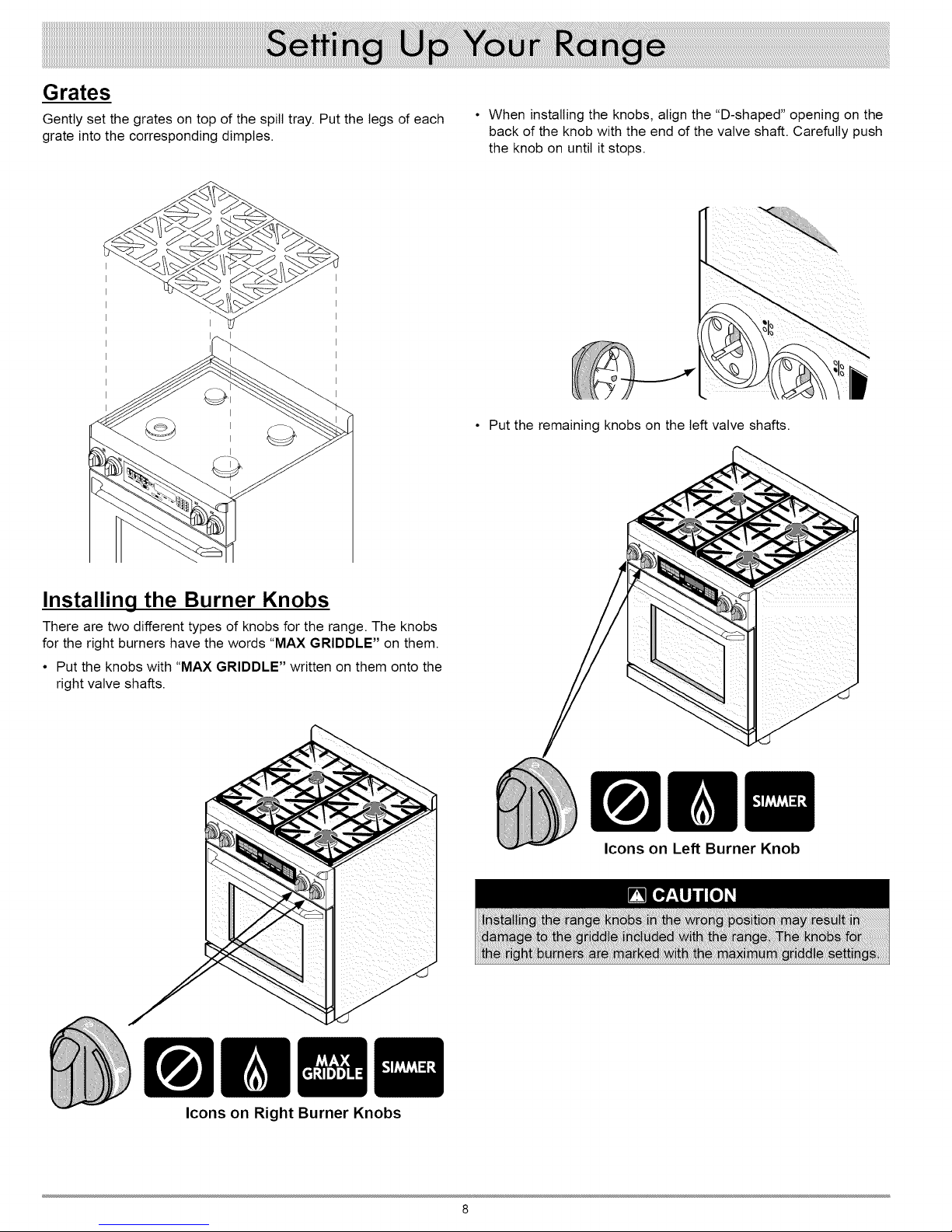
Grates
Gently set the grates on top of the spill tray. Put the legs of each
grate into the corresponding dimples.
• When installing the knobs, align the "D-shaped" opening on the
back of the knob with the end of the valve shaft. Carefully push
the knob on until it stops.
• Put the remaining knobs on the left valve shafts.
Installing the Burner Knobs
There are two different types of knobs for the range. The knobs
for the right burners have the words "MAX GRIDDLE" on them.
• Put the knobs with "MAX GRIDDLE" written on them onto the
right valve shafts.
Icons on Left Burner Knob
Icons on Right Burner Knobs
Page 11
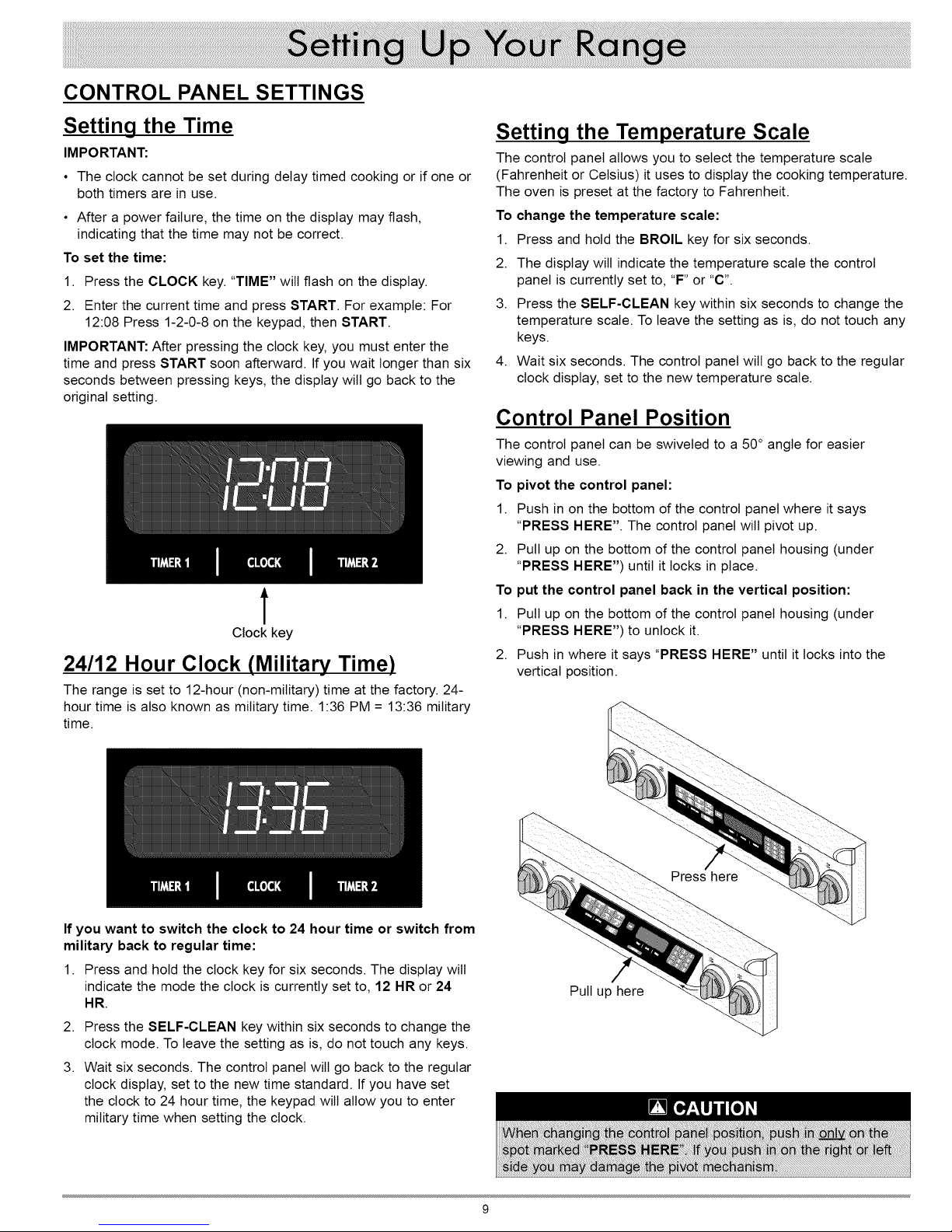
CONTROL PANEL SETTINGS
Setting the Time
IMPORTANT:
• The clock cannot be set during delay timed cooking or if one or
both timers are in use.
• After a power failure, the time on the display may flash,
indicating that the time may not be correct.
To set the time:
1. Press the CLOCK key. "TIME" will flash on the display.
2. Enter the current time and press START. For example: For
12:08 Press 1-2-0-8 on the keypad, then START.
IMPORTANT: After pressing the clock key, you must enter the
time and press START soon afterward. If you wait longer than six
seconds between pressing keys, the display will go back to the
original setting.
t
Clock key
24/12 Hour Clock (Military Time)
The range is set to 12-hour (non-military) time at the factory. 24-
hour time is also known as military time. 1:36 PM = 13:36 military
time.
Setting the Temperature Scale
The control panel allows you to select the temperature scale
(Fahrenheit or Celsius) it uses to display the cooking temperature.
The oven is preset at the factory to Fahrenheit.
To change the temperature scale:
1. Press and hold the BROIL key for six seconds.
2. The display wilt indicate the temperature scale the control
panel is currently set to, "F" or "C".
3. Press the SELF-CLEAN key within six seconds to change the
temperature scale. To leave the setting as is, do not touch any
keys.
4. Wait six seconds. The control panel wilt go back to the regular
clock display, set to the new temperature scale.
Control Panel Position
The control panel can be swiveled to a 50° angle for easier
viewing and use.
To pivot the control panel:
1. Push in on the bottom of the control panel where it says
"PRESS HERE". The control panel will pivot up.
2. Pull up on the bottom of the control panel housing (under
"PRESS HERE") until it locks in place.
To put the control panel back in the vertical position:
1. Pull up on the bottom of the control panel housing (under
"PRESS HERE") to unlock it.
2. Push in where it says "PRESS HERE" until it locks into the
vertical position.
If you want to switch the clock to 24 hour time or switch from
military back to regular time:
1. Press and hold the clock key for six seconds. The display will
indicate the mode the clock is currently set to, 12 HR or 24
HR.
2.
Press the SELF-CLEAN key within six seconds to change the
clock mode. To leave the setting as is, do not touch any keys.
3.
Wait six seconds. The control panel wilt go back to the regular
clock display, set to the new time standard. If you have set
the clock to 24 hour time, the keypad will allow you to enter
military time when setting the clock.
Pull up here
Page 12

IMPORTANT:
• Avoid spills as much as possible. The porcelain surfaces of
the grates, spill trays, and burner caps are acid-resistant but
not acid-proof. Some foods can cause permanent damage if
allowed to remain on porcelain surfaces.
• To keep the burners operating properly, keep the burner
igniters, burner rings and burner caps clean and dry. See
pages 24-25 for cleaning instructions.
Selecting the Cookware
For overall safety and best cooktop performance, select the
correct cooking utensil for the food being cooked. Improperly
selected cooking utensils will not cook evenly or efficiently.
Use cookware that:
• Has flat, smooth bottoms.
• Is welt balanced.
• Has tight fitting lids to keep heat, odors, and steam in.
Lighting A Burner
Each burner control knob has a small diagram next to it ,=. ,,,,
to tell you which burner itoperates.
oo
To light a burner:
1. Push in on the knob and turn it counter-clockwise to the HIGH
position. The igniter for the burner wilt spark repeatedly until it
lights. The spark makes a "clicking" sound. The burner should
light within four seconds.
!
Burner knob settings
OFF HIGH LOW
2. The flame should burn evenly around the perimeter of the
burner, except underneath each grate support finger, where
the flame height is reduced by Dacor's Smart Flame feature.
A normal flame is steady and blue in color. Foreign material
in the gas line, especially in new construction, may cause an
orange flame during initial operation. This wilt disappear with
further use. Small yellow tips on the ends of the flames are
normal when using LP gas.
3. If a burner does not ignite, the igniter continues to spark, or if
the flame is not spread evenly around the burner cap, see the
Before You Call for Service section on page 30.
4. Place the cooking utensil on the grate.
5. Adjust the flame to the level necessary to perform the desired
cooking process.
IMPORTANT: When the cooktop is cool the igniter may continue
to spark ifthe control knob is set to the tow position. The burner
wilt stop sparking when warm. The tendency to spark when
cold can be reduced by operating the burner at a higher flame
setting for about 60 seconds. After 60 seconds, lower the flame
to cook. The burner wilt also warm up faster if a utensil is placed
on the grate. The igniter wilt also spark automatically if the flame
isdistorted by a draft or by the household ventilation system.
Eliminate any drafts or reduce the ventilation blower speed to
reduce this type of problem.
10
Page 13

Cooktop Tips:
• Dacor's SimmerSear feature allows you precision control of the
flame. The larger the burner size, the wider the range of control.
See page 6 for the heat ranges of the different burners.
• Food cooks just as quickly at a gentle boil as it does at a
vigorous, rolling boil. Maintaining a higher boil than necessary
wastes energy and cooks moisture, food flavor, and nutrients
out of the food.
Use a low or medium flame when cooking with utensils that are
poor conductors of heat, such as glass, ceramic, or cast iron.
Reduce the flame until it covers approximately 1/3 of the utensil
diameter. Doing so wilt ensure even heating and reduce the
likelihood of burning or scorching the food.
Using the Griddle
For best results, allow the griddle to preheat for about 10 minutes
before you start to cook.
1. Before using the griddle for the first time, wash it in hot, soapy
water. Rinse it and allow it to dry thoroughly.
2. With all of the burners off and the range cool to the touch, put
the griddle over the top of the _ grate on the range*. The
grease trap goes toward the back of the range. Fit the tabs
that stick out of the bottom of the feet into the inside corners
of the grate. When it is correctly installed, the griddle wilt rest
securely about 1/2" above the top surface of the grate. It may
rock slightly, which is normal.
3. Turn the right front burner knob to the light (high) position.
Once tit, turn the knob to the MAX GRIDDLE position, or lower
if desired. DO NOT keep the burner knobs higher than the
MAX GRIDDLE setting after they are lit!
4. Repeat step 3 for the right rear burner knob.
During cooking be careful with metal utensils on the surface
because they can scratch the non-stick coating.
Clean the griddle after each use. See page 27 for instructions.
* The right grate has burners of the same size in the front and
back for even heating.
Line up griddle on
corners of grate
Grease trap
toward back
/
I
I
I I
I
I
Do not turn burners higher than the "MAX GRIDDLE" setting
when using the griddle!
11
Page 14

Before You Cook...
To Remove the Standard Oven Racks:
• When you use your oven to bake or roast, it preheats
automatically. The preheat cycle rapidly brings the oven
chamber up to the proper cooking temperature. It takes several
minutes to preheat the oven. Preheat time depends on the
temperature settings. The time may be longer depending on the
type of electrical supply in your community. There is no preheat
cycle for any of the broil modes.
• After you pull food out of the oven, itwill continue to cook. This
process is called "carry-over". The larger the portion of food, the
longer it wilt cook. It is best to let the meat rest after it comes
out of the oven for 10 to 15 minutes before carving. Doing so
wilt allow the meat to retain its juices and make it easier to
carve.
Dacor recommends turning the oven on for one hour at 500°F
to burn off any residual oils used during the manufacturing
process. Any of these oils left on the inner parts can cause an
undesirable smell the first few times the oven is used.
Racks
You may use either rack type on any level.
• If you want to remove an oven rack, grasp it with both hands
and pull gently straight out toward you until it stops.
• To remove the rack completely, lift the front of the rack up about
six inches and continue to pull it out. Lifting the rack releases
the safety notches. The safety notches reduce the chances of a
rack coming out of the oven accidentally.
To Insert Your GlideRack Oven Rack:
Your oven comes with a Dacor GtideRack oven rack. You can pull
the GtideRack oven rack out further than the standard racks and
still support heavy pots and pans full of food. It is great for heavier
foods and the optional Dacor baking stone.
1. Hold the GtideRack oven rack with the guides fully extended
away from you (see the diagram below).
2. Align both sets of safety clips (right and left) on the back of the
guides with the oven rack supports as shown.
3. Begin to slide the rack in, lifting the front safety clips over the
front of the oven rack supports.
4. Push the rack all the way to the back.
5. Grasp the rack in the center of the front and pull. The rack
should come forward while the guides remain in place.
Guides
To Insert the Standard Oven Racks:
1.
Insert the end of the rack with the safety notches into the oven
first.
2.
Attach both sides of the rack to the rack supports in the oven
as shown in the diagram below.
3.
Begin to slide the rack in, and then, lift up so that the safety
notches clear the ends of the rack supports.
4.
Push the rack all the way in with both hands.
Back of rack
/
Rack support
/
Front of rack
Safety notch
Front of rack
Slide rack supports
between back safety clips
Rack support
To Remove Your GlideRack Oven Rack:
Grasp it with both hands and pull gently straight out toward you
until it stops. To remove the rack completely, lift the front up about
six inches and continue to pull it out. Lifting it releases the safety
clips. The safety clips reduce the chance of the rack coming out of
the oven accidentally.
12
Page 15

Starting Your Oven
1. Adjust the racks to the appropriate level.
2. Determine the best cooking mode for the type
of food to be cooked.
Select from the following:
• CONVECTION BAKE - A combination of the convection fan and
a bottom heat source. Good for single rack items in a deep pan.
• CONVECTION BROIL - A combination of the convection fan
and a top heat source. Good for items that do not need to be
flipped, such as thinner cuts of meat, fish, and garlic bread.
• PURE CONVECTION TM - Uses convection cooking only for
even heat. Use for baked goods and multiple rack cooking.
• BAKE - Cooks with a bottom heat source only. Commonly used
for basic recipes.
• BROIL - Cooks using a top heat source alone. Use for grilling
smaller cuts of meat or toasting bread.
• CONVECTION ROAST - Combines top and bottom heat
sources with the convection fan. Best for rib roasts, turkeys,
chickens, etc.
See pages 15 to 17 for detailed descriptions of the various
cooking modes.
You can enter any temperature between 100°F and 555°F. The
suggested broil temperature is 555°F. On model ER48D the same
START key is used to start both ovens.
If you are using one of the bake or roast modes, "PRE-" for
preheating, along with the current oven temperature wilt appear
on the display until the oven reaches the set temperature. Once
the set temperature is reached, the oven wilt beep and "PRE-" will
disappear from the display. Carefully place your food in the oven.
Excessive browning will occur if you put the food in too soon.
Turning Off Your Oven
• To turn the oven off, press the CANCEL/
SECURE key 0.
NOTE: After you turn off the oven, the cooling fans may continue
to run until the range's internal parts have cooled down.
Changing the Temperature
(after you press START)
1. Press the key for the current cooking mode. The current
cooking mode appears on the display (for example BAKE).
2. Enter the temperature on the keypad (for example 3-7-5) and
press START.
Changing the Oven Cooking Mode
(after you press START)
IMPORTANT: The broil modes will not work when the meat probe
is connected.
3.
Press the key for the desired cooking mode 0. The preset
(jump-in) temperature will appear on the display (see page 14
for more details).
4.
Press START O, to cook at the preset temperature. Or you
may enter a different cooking temperature (for example 3-5-0)
on the number keypad _), then press START.
O O O
To change to a different cooking mode while the oven is on, for
example to change from convection bake to bake:
1. Press the key for the new cooking mode, for example BAKE.
2. Press START.
O
13
Page 16

Preset (Jump-in) Temperature Settings
Your oven has a preset "jump-in" temperature setting for each
of the cooking modes to reduce the need to always enter the
temperature. See the table below. See "Starting Your Oven" on
page 13 for directions on how to cook at the preset temperature.
BAKE
CONVECTION BAKE
PURE CONVECTION 325°F
CONVECTION ROAST 375°F
BROIL 555°F
CONVECTION BROIL 555°F
Lock-Out Feature
If you want to disable the keys on the control panel when the
oven is not in use:
• Push and hold the CANCEL/SECURE key @ for about four
seconds. The control panel keys will stop working and "OFF"
will appear on the display. Only the CANCEL/SECURE and the
oven light keys remain functional.
• To reactivate the control panel, press and hold the CANCEL/
SECURE key for four seconds.
350°F
325°F
12 Hour Timer Feature
Your range is equipped with a feature that automatically turns
the oven off after 12 hours of continuous use. The 12 hour timer
resets if you change the cooking temperature or cooking mode.
This feature does not apply to the cooktop.
The range ships from the factory with the 12 hour timer enabled.
To disable or enable the 12 hour timer feature:
• With the oven off, push and hold the TIMER 1 key IB for about
ten seconds, until the control panel beeps. ON will appear on
the display if the 12 hour timer is enabled.
• Push the SELF CLEAN key _) to disable (or enable) the 12
hour timer.
• Push START O to save the changes and return to the clock
display.
O
O O O
14
Page 17

Understanding the Various Oven Modes
The three basic styles of cooking in an oven are:
o:o BAKING - The gentle cooking of dry goods such as cookies, cakes, souffles, etc.
+ ROASTING - The cooking of meats or vegetables over a period of time.
+ BROILING - Cooking with an intense heat for a short amount of time.
BAKE
Uses only a heat source from below the food.
This mode is the stand-by, non-convection mode.
All baked items will turn out nicely in this mode.
Bakinq Tips
• Follow your recipe's original cooking time and temperature.
• Do not open the oven door frequently during baking. Look
through the oven door window to check the progress of baking
whenever possible.
Cookies burn on the bottom.
Cookies are too brown on top.
Oven door opened too often. Set timer to shortest recommended cooking time and check
Incorrect rack position used. Change rack position.
Dark, heat absorbing cookie Use shiny, reflective cookie sheets.
sheets used.
Rack position being used is too
high.
Food placed in oven during
preheat.
• Use the timers to determine baking time.
• Use the lowest rack position.
• Wait until the shortest recommended baking time before
checking the food. For most baked goods, a wooden toothpick
placed in the center should come clean when the food is done.
food when timer beeps. Use door window to check food.
Change rack position.
Wait until oven is preheated.
Incorrect baking mode being used. See "Select from..." section on page 13 for guidelines.
Cakes burn on the sides or
are not done in the center.
Cakes crack on top. Oven temperature too high. Reduce oven temperature.
Cakes are not level. Oven and/or oven rack not level. Level oven and rack as needed.
Pies burn around the edges or
are not done in the center.
Oven temperature too high. Reduce oven temperature.
Dark, heat absorbing cake pans Use shiny, reflective cake pans.
used.
Oven temperature too high.
Dark, heat absorbing pans used.
Reduce oven temperature.
Use shiny, reflective pans.
Reduce number of pans.
15
Page 18

Understanding the Various Oven Modes (cont.)
Your range offers three convection cooking
modes:
• Pure Convection
• Convection Bake
• Convection Roast
As a general rule, in the convection modes time is about 25%
shorter. Set the timer 15 minutes before the shortest stated time
and add more time if necessary.
For Pure Convection and Convection Bake Modes:
Some recipes, especially those that are homemade, may
require adjustment and testing when converting from standard
to convection baking. If you are unsure how to convert a recipe,
begin by preparing the recipe using the standard bake settings.
After achieving acceptable results, follow the convection
guidelines in the Dacor Cooking Guide. If the food is not cooked
to your satisfaction during this first convection trial, adjust one
recipe variable at a time (such as cooking time, rack position,
or temperature) and repeat the convection test. If necessary,
continue adjusting one recipe variable at a time until you get
satisfactory results.
PURE CONVECTION
The uniform air circulation provided by Pure
Convection allows you to use more oven capacity
at once. Use this mode for single rack baking, multiple rack
baking, roasting, and preparation of complete meals. Many foods,
such as pizzas, cakes, cookies, biscuits, muffins, rolls, and frozen
convenience foods can be successfully prepared on two or three
racks at a time. Pure Convection is also good for whole roasted
duck, lamb shoulder and short leg of lamb.
AIR FLOW
____ .... o
For Multiple Rack Baking
• Typically, when baking on two racks, use rack positions #1 and
#3 or #2 and #4 (counting from the bottom up).
• When adapting a single rack recipe to multiple rack baking, it
may be necessary to add to the baking time due to the extra
bulk of the food in the oven.
CONVECTION BAKE
Use this mode for single rack baking. The
combination of the convection fan and bottom
heat source is best for fruit crisps, custard pies, double-crusted
fruit pies, quiches, yeast breads in a loaf pan, and popovers. Also,
items baked in a deep ceramic dish or earthenware clay pots are
best in this mode. Most of these items cook in a deep pan and
require browning on the top and bottom.
CONVECTION ROAST
Your range's convection roast mode uses a
combination of the convection fan and heat
sources above and below the food. Best for rib roasts, turkeys,
chickens, etc.
Roastinq Tips
All baking modes can be used to successfully roast in your oven.
However, the convection roast mode is recommended to produce
meats that are deliciously seared on the outside and succulently
juicy on the inside in record time. Foods that are exceptional,
when prepared in the convection roast mode, include: beef, pork,
ham, lamb, turkey, chicken, and cornish hens.
Always roast meats fat side up in a shallow pan, using a roasting
rack. Always use a pan that fits the size of the food being
prepared. The broiler pan and grill, accompanying the oven, can
be used in most cases. No basting is required when the fat side
is up. Do not add water to the pan. It will cause a steamed effect.
Roasting is a dry heat process.
Poultry should be placed breast side up on a rack in a shallow
pan that fits the size of the food. Again, the broiler pan and grill
accompanying the oven can be used. Brush poultry with melted
butter, margarine, or oil before and during roasting.
When using the roast mode, do not use pans with tall sides. They
interfere with the circulation of heated air over the food.
If using a meat thermometer, insert the probe halfway into the
center of the thickest portion of the meat. For poultry, insert the
thermometer probe between the body and leg into the thickest
part of the inner thigh. To ensure an accurate reading, the tip of
the probe should not touch bone, fat, or gristle. Check the meat
temperature 2/3of the way through the recommended roasting
time. After reading the meat thermometer once, insert it ½ inch
further into the meat, then take a second reading. If the second
temperature registers below the first, continue cooking the meat.
Remove meats from the oven when the thermometer registers 5
to 10°F below the desired temperature. The meat will continue to
carry-over.
Allow roasts to stand 15 to 20 minutes after roasting in order to
make carving easier.
Roasting times always vary according to the size, shape, and
quality of meats and poultry. Less tender cuts of meat are best
prepared in bake and may require moist cooking techniques.
Follow your favorite cookbook recipes.
Reduce spatter by lining the bottom of the roasting pan with lightly
crushed aluminum foil.
16
Page 19

Understanding the Various Oven Modes (cont.)
Your range offers two broil modes:
• Broil
• Convection Broil
Broiling is a quick and flavorful way to prepare many foods,
including steaks, chicken, chops, hamburgers, and fish. In the
interest of safety, keep the oven door completely shut when using
the broil modes.
BROIL
Uses a top heat source. Best for broiling smaller
amounts of food.
CONVECTION BROIL
This mode uses a combination of the convection
fan and a top heat source. It is best for items that
do not need to be flipped such as, thinner cuts of meat, fish, and
garlic bread.
Timers
Broiling Tips
• If the meat probe is plugged into the oven, disconnect and
remove it before selecting one of the broil modes. The broil
modes do not function with the meat probe connected.
• It is normal and necessary for some smoke to be present to
give the food a broiled flavor.
• Setting the timer is recommended to time the broiling process.
• Always use a broiler pan and grill to provide drainage for
excess fat and grease. Doing so will reduce spatter, smoke, and
flare-ups.
• Start with a room temperature broiler pan for even cooking.
• Use tongs or a spatula to turn and remove meats. Never pierce
meat with a fork because the natural juices will escape.
• Broil food on the first side for a little more than half of the
recommended time, then season and turn. Season the second
side just before removing the food from the oven.
• To prevent sticking, lightly grease the broiler grill. Excess
grease wilt result in heavy smoke. For easier cleaning, remove
the broiler pan and grill when the food is removed.
While a timer is running you can:
• Press CLOCK to view the current time
• Press TIMER 1 to view the time left on (or set) TIMER 1
• Press TIMER 2 to view the time left on (or set) TIMER 2
IMPORTANT: Pressing the CANCEL/SECURE key does NOT
turn off the timers.
Your range is equipped with 2 built-in timers:
• You can use both of them at the same time.
• You can time from 1 minute up to 11 hours and 59 minutes.
To Use the Timers on Your Range:
1. Press the TIMER 1 or TIMER 2 key.
2. Enter the hours and minutes to be timed on the keypad and
press START. To enter 11 hours, 30 minutes, press 1-1-3-0. To
time 25 minutes, press 2-5. When you press START, the time
will appear on the display and will begin to count down.
The alarm (a beeping sound) will go off when the timer is done
counting down. Timer 1 and Timer 2 have different beeping
patterns so you can easily tell which one has gone off. There is
also a special beeping pattern when both alarms go off at the
same time.
1 1 second on, 1 second off, repeat
2 1 second on, 1 second off, 2 seconds on, 1 second
off, repeat
1 and 2 2 seconds on, 1 second off, repeat
To change the amount of time on a timer:
1 Press the TIMER 1 or TIMER 2 key
2 Enter the new time on the keypad and press START
To stop a timer before time runs out:
• Press the TIMER 1 or TIMER 2 key twice
• The timer will stop and the display will read 0:00
Press the TIMER 1 (or TIMER 2) key to stop the alarm
17
Page 20

Delay Timed Cooking Features
If you want to set the oven to automatically turn itself on or off at a
later time, you can use the delay timed features.
Things to Know About Delay Timed Cooking:
• The delay timed options work for all of the various cook modes,
except broil and convection broil.
• You may use the timers while using the delay timed features.
The timers do not have an effect on any of the delay timed
cooking options.
• The delay timed cycle can be canceled at any time by pushing
CANCEL/SECURE.
Delay Timed Cooking Set-up
Before Setting the Controls:
• Adjust the racks to the appropriate level.
• Put the food in the oven.
The Three Ways to Use Delayed Timed Cooking:
1. Set the time the oven turns on (START TIME) and the amount
of time it cooks (COOK TIME) before going into hold mode.
2. Set the START TIME only, then turn the oven off manually
when you are done cooking.
3. Turn the oven on manually, then set the amount of COOK
TIME. The oven will go into hold mode after the time expires.
To Set both the Start and Cook Times:
1. Press the key for the desired cooking mode (except the broil
modes.)
2. Enter the desired cooking temperature on the number keypad
and press START.
3. Press the START TIME key.
4. Enter the time you want the oven to start on the keypad and
press START. For 12:35, press 1-2-3-5. You may enter a time
up to 11 hours and 59 minutes ahead of the present time.
5. Press the COOK TIME key.
6. Enter the amount of time you want the oven to be on (after it
starts), using the keypad and press START. For 1 hour and
35 minutes, press 1-3-5. For 25 minutes, press 2-5. You may
enter from 1 minute up to 11 hours and 59 minutes.
7. The oven will start at the start time entered, cook for the
amount of cook time entered and then, go into hold mode.
IMPORTANT: The time required to preheat the oven must be
included in the cook time. For cooking temperatures 350°F and
below, add 13 minutes to the cook time. Increase the cook time as
the temperature increases above 350°F.
To Set the Start Time Only:
1. Press the key for the desired cooking mode (except the broil
modes).
2. Enter the desired cooking temperature on the number keypad
and press START.
3. Press the START TIME key.
4. Enter the time you want the oven to start on the keypad and
press START. For 12:35, press 1-2-3-5. You may enter a time
up to 11 hours and 59 minutes ahead of the present time.
5. The oven will start at the start time entered. Since you did
not enter a cook time, you must turn the oven off manually by
pressing CANCEL/SECURE.
To Set the Cook Time Only:
1. Press the key for the desired cooking mode (except the broil
modes.)
2. Enter the desired cooking temperature on the number keypad
and press START. The oven will turn on.
3. Press the COOK TIME key.
4. Enter the amount of time you want the oven to be on, using
the keypad and press START. For 1 hour and 35 minutes,
press 1-3-5. For 25 minutes, press 2-5. You may enter from 1
minute up to 11 hours and 59 minutes.
5. The oven wilt cook for the amount of time entered and then, go
into hold mode.
Other Things to Know About Delayed Timed
Cooking
When the oven is in delay timed mode...
1. Push the CLOCK key to view the time.
2. Push the START TIME key to view the current start time
setting.
3. Push the COOK TIME key to view the current cook time
setting.
HOLD Mode
• When the oven reaches the end of the cook time you have set,
it will go into "hold" mode (HLD appears on the display.) The
oven will keep the temperature at 150°F for two hours.
• Press CANCEL/SECURE to turn the oven all the way off.
• To prevent sickness, do not allow foods to remain in the oven
after it is off (after hold mode turns off.)
18
Page 21

Using the Meat Probe
When you cook foods like roasts and poultry,
the internal temperature is the best way to tell
when the food is properly cooked. Your oven's
meat probe is an easy way to take the guesswork out of roasting.
You can use it to cook food to the exact temperature you desire.
The probe can be set from 100°F to 200°F.
NOTE: The meat probe does not work with the BROIL or
CONVECTION BROIL modes.
To use the meat probe:
1. Prepare the meat for cooking prior to setting the oven. Insert
the meat probe skewer into the center of the meat. Make sure
that the skewer is not inside any fatty portions of the meat and
does not touch any bones. The point should rest in the thickest
part of the meat. When you are cooking fowl, the tip of the
skewer should rest toward the center of the bird.
2. Before putting the meat in the oven, close the door and push
the BAKE, CONVECTION BAKE, PURE CONVECTION
or CONVECTION ROAST key. The preset temperature wilt
appear on the display. If you want to cook using a different
oven temperature, enter it on the keypad.
3. Press START.
4. Allow the oven to preheat.
5. Once the oven has preheated, put the meat in the oven using
potholders. Plug the meat probe into the connector inside the
oven.
6. Push the PROBE key. The preset temperature (160°F) will
appear on the display.
7. If you want to cook using a different probe temperature, enter
it on the keypad. Use the USDA Minimum Safe Cooking
Temperature Chart as a guideline for the type of meat you
are cooking.
8. Press START. If you do not press START, the probe mode will
start automatically after six seconds.
When the meat probe is in use, the oven will automatically
control the cooking time. The temperature on the display during
cooking is the temperature measured inside the meat. The oven
wilt continue to cook until the meat temperature reaches the
temperature you have entered.
When the meat is done, the oven wilt go into hold mode. The
temperature wilt reduce to 150°F for two hours to keep the
meat warm and safe for serving. To prevent sickness, do not
allow foods to remain in the oven after it has turned off. Press
CANCEL/SECURE to cancel hold mode and turn the oven
completely off.
To change the meat probe temperature during
cooking:
1. Press PROBE. The current probe temperature will appear on
the display.
2. Enter the new temperature. The oven wilt automatically
change to the new probe temperature. If you do not enter
a temperature, the oven will continue to cook at the current
setting.
To change the cooking mode during meat probe
cooking:
1. Press the key for the new desired cooking mode (BAKE,
CONVECTION BAKE, PURE CONVECTION, or
CONVECTION ROAST).
2. You may enter a new temperature on the keypad or use the
default temperature.
3. Push START. The oven will cook until the meat's internal
temperature reaches the previously selected meat probe
temperature.
To cancel meat probe operation while the oven is
cooking:
• Press the PROBE key twice. Disconnect the meat probe from
the connector. If you do not disconnect the meat probe, an error
tone wilt sound. The oven will return to any previous settings
that were entered before the PROBE key was pressed.
Plug
Skewer
/
Meat probe
19
Page 22

Important details about the meat probe:
• You must select the specific cooking mode (BAKE,
CONVECTION BAKE, PURE CONVECTION, or CONVECTION
ROAST) before you press the PROBE key.
• There is no preheat cycle when the meat probe feature is used.
For best results, select the mode and allow the oven to preheat
prior to starting the meat probe feature.
• The meat probe cannot be used with the broil modes. An error
tone wilt sound.
• If you disconnect the meat probe from the oven during cooking,
probe mode will be cancelled and the oven will continue to cook
until you press CANCEL/SECURE.
• If you leave the meat probe plugged into the oven, but the meat
probe feature is not selected on the control panel, "PRB" will
flash on the screen.
• The meat probe function wilt automatically cancel after 30
seconds if the meat probe is not connected. "PRB" will flash on
the display.
• The meat probe feature takes precedence over the delay timed
cooking feature. Delay timed cooking does not work when the
meat probe is in use. The oven wilt continue to cook the meat
until it reaches the selected meat probe temperature. However,
if delay timed cooking was selected before the PROBE key was
pressed, the oven will shut off instead of going into hold mode.
USDA Minimum Safe Internal Cooking
Temperatures for Various Foods
Dehydrating/Defrosting
Your range can be used to dehydrate or defrost foods at low heat
settings in the Pure Convection mode.
To dehydrate or defrost foods:
1. Adjust the racks to the appropriate level.
2. Place the food on the center of the oven rack. (If you are
dehydrating, prepare food as recommended, then place it on a
drying rack.)
3. Press the PURE CONVECTION key.
4. To defrost meats, enter the temperature to 150°F on the
keypad. To dehydrate, start by setting the temperature
according to the table below. When dehydrating, you may
need to experiment with higher temperatures.
5. Press START.
Fruit
Vegetables
Meat
Dacor recommends that you use one of the timers to time the
process.
100°F
125°F
150°F
Beef, Pork Veal, Lamb 160°F
Turkey, Chicken 165°F
Medium Rare 145°F
Medium 165°F
Welt Done 170°F
Welt Done 170°F
160°F
Pre-cooked (reheat)
NOTE: The minimum safe internal cooking temperatures are subject to
change. There are changes in bacteria and the temperatures required to
eradicate them. For the most current information, contact the USDA.
140°F
Dehydrating Tips
Equipment Recommended:
• Half sheet pan or jelly roll pan with ½" rim all the way around
• Baking rack that fits inside the half sheet pan
• Cheesecloth
• 4 quart sauce pot with lid
• Steamer basket that fits inside 4 quart saucepan, One that is
perforated and opens up will work well,
• Slotted spoon
• Paper towels
• A sharp knife
When you dehydrate:
1. Wash and remove excess moisture from all fruits and
vegetables before dehydrating.
2. Cut fruits and vegetables into uniform pieces.
3. You can add honey, spices, lime juice, or orange juice to give
the fruit a different flavor.
4. It is best to dehydrate on a baking rack with a pan underneath
to catch any juices. If the fruit is small, use cheesecloth
over the rack. If you use a rack, it will allow for maximum air
circulation around the fruit. The cheesecloth will prevent the
fruit from sticking to the rack.
5. Place the food onto the center of the oven rack.
USDA Meat and Poultry Hotline: Phone: (800) 535-4355
www.fsis.usda.gov
20
Page 23

Dehydrating Tips (cont.)
Solving Discoloration Problems:
To prevent darkening during dehydration and storage, you should
steam blanch apples, apricots, peaches, nectarines, pears, or
foods that will oxidize.
To
steam blanch:
a.
Add 1 inch of water to a 4 quart sauce pot. Insert the steam
basket and place the fruit in it.
b.
Cover the pot and steam for 1 to 2 minutes.
C.
Remove with a slotted spoon and dab with a paper towel to
remove excess moisture before dehydrating.
d.
Apples, pears, pineapples, and some other fruits wilt brown
or darken during dehydration. To prevent discoloration,
dip fruits in pineapple juice or lemon juice after steam
blanching.
Creating a Candied Effect
To give fruit a candied effect and to help retain color, blanch them
in a simple syrup. You can candy the fruits mentioned above as
welt as figs and plums. The basic ratio for a simple syrup is 1
cup of sugar to 1 cup of water. Add these ingredients to a 4 quart
stock pot and bring to a boil. Stir until all the sugar dissolves.
Remove the saucepan from the cooktop and allow it to cool. Dip
fruit into the simple syrup after it has cooled.
Preventing Tough Skins
You should water blanch items with tough skins such as grapes,
prunes, dark plums, cherries, figs, and some types of berries.
Water blanching these types of fruit wilt crack the skins so
that moisture can escape and dehydration can be done more
effectively.
To water blanch:
a. Bring 2 quarts of water to boil in a 4 quart sauce pot.
b. Drop the fruit in the water for 1 to 2 minutes, or until the skin
begins to crack.
c. Remove the fruit with a slotted spoon and dab dry with a
paper towel before dehydrating. The pit can be left inside or
removed half way through the dehydrating process.
Proofing
You can use your range to proof yeasted doughs at a low and
draft-free temperature using the bake mode.
1. Press the BAKE key.
2. Enter the temperature of 100°F on the keypad.
3. Press START.
4. Place the dough in a greased bowl inside of the oven. Cover it
with either a damp cloth or plastic wrap coated with a nonstick
spray.
5. Turn on the oven lights.
6. Set the timer for the amount of rise time in the recipe.
Defrosting Tips
• Food that takes an exceptional amount of time to defrost will not
defrost welt in a convection oven.
• You should not defrost anything that would normally take over 2
hours to thaw. The food wilt begin to spoil because the defrost
temperature is not high enough to cook the food.
• If you have a partially defrosted turkey, rib roast, or other large
cut of meat, you may continue to defrost it in your convection
oven. If wing tips and legs begin to dry out when you defrost
poultry, you may wrap the tips with aluminum foil.
• If you are defrosting a small cut of meat, lay it on a flat cookie
sheet with a 1-inch rim to catch juices as the meat thaws.
• Thick, frozen casseroles such as lasagna wilt not defrost welt in
your oven. Instead, defrost according to the food manufacturer's
suggestions. You may also defrost casseroles in the refrigerator
overnight. You should leave the food in its original container and
keep it covered.
• You can bake some foods from frozen. Some examples are:
pizza, frozen pastries, croissants, cookies, etc. Before baking
frozen food, allow the oven to preheat.
21
Page 24

Food Placement
NOTE: The rack positions mentioned below are counting from the
bottom up
• Typically, when baking on 2 racks, use rack positions #2 and #4
or #1 and #3. When baking on 3 racks, use rack positions #1,
#3, and #5.
• Turn pans on the racks so that the long sides run left to right, as
you face them.
• When you are cooking a food item that is very heavy, use the
Dacor GlideRack oven rack. You can pull it out further than a
conventional rack, making it easier to check the food, stir, or
add ingredients.
• Heavier roasting pans and dishes will cook better on rack
position #1.
• When using a baking stone, use rack position #1 for best
results
• If you put a baking stone on the GtideRack oven rack, instead
of one of the standard oven racks, you can pull the stone out of
the oven further, making pizza easier to remove.
For roasting, Dacor's optional "V" shaped rack and broil/roast
pan works best to allow air circulation around the food.
Dacor's roasting pan works particularly well and two of them will
fit side by side in a 30-inch oven.
High Altitude Cooking
Due to the lower atmospheric pressure at higher altitudes, foods
tend to take longer to cook. Therefore, recipe adjustments should
be made in some cases. In general, no recipe adjustment is
necessary for yeast-risen baked goods, although allowing the
dough or batter to rise twice before the final pan rising develops
a better flavor. Try making the adjustments below for successful
recipes. Take note of the changes that work best and mark your
recipes accordingly. You may also consult a cookbook on high-
altitude cooking for specific recommendations.
Oven Rack Positions
The Best Use of Bake Ware
• You should bake cakes, quick breads, muffins, and cookies
in shiny, reflective pans for light, golden crusts. Avoid old,
darkened, warped, dented, stainless steel, and tin-coated pans.
They heat unevenly and will not give good baking results.
• Use medium gauge aluminum sheets with tow sides when
preparing cookies, biscuits, and cream puffs. Dacor cookie
sheets, with their low profiles, will give you the best results.
• Bake most frozen foods in their original foil containers, placed
fiat on a cookie sheet. Follow the package recommendations.
When using glass bake ware, reduce the recipe temperature
by 25°F, except when baking pies or yeast breads. Follow the
standard recipe baking time for pies and yeast breads.
• Use the pan size and type recommended by the recipe for best
results
7OOO
22
Page 25

Your Oven's Self-Clean Feature
About the Self-Clean Cycle
• The oven will run better and produce better
baked goods when it is clean. During self-
cleaning, the oven is heated to very high
temperatures which burn off any deposits on
the surfaces of the oven. Self-cleaning eliminates the need for
manual scrubbing of interior surfaces. The self-clean process
takes about three hours.
• It is normal for the oven to emit smoke during the first few
self-clean cycles. It is also normal for the oven to emit popping
sounds during self-cleaning. These sounds are caused by the
expansion and contraction of metal surfaces when the oven
heats up and cools down.
• Self-clean mode will not function if the meat probe is connected.
2. Clean soil from the porcelain surfaces of the door outside of
the door gasket. Rinse surfaces welt with a solution of vinegar
and water, then wipe dry. Heavily soiled areas may be cleaned
with a non-scratching scouring pad.
3. Clean the door gasket by dabbing it with a solution of water
and mild soap.
4. Turn on kitchen fans or vents to help remove odors during the
self-clean cycle.
5. Make sure the oven door is shut.
6 Press the SELF CLEAN key
7 Press START
The control panel automatically locks the oven door during self-
cleaning. The latch prevents the door from being opened since
the high interior oven temperatures can easily cause injury. If the
door is not shut, "DOOR" will appear on the display. To correct the
problem, press CANCEL/SECURE and wait approximately one
minute, then close the door. When the door is properly closed,
start the self-clean process again.
The display shows the self clean cycle status:
• "CLEAN" indicates that self clean is in process.
• "LOCK" indicates that the door is latched.
• "ON" indicates that the heating elements are on.
How to Use the Self-Cleaning Feature
1. Before self-cleaning the oven, remove the racks, the
convection filter, all cookware (pots, pans, forks, etc.), the
meat probe, foil and any other loose objects from the oven
chamber. See page 26 for instructions on how to remove and
clean the filter.
Display When Self-Clean is ON
If you want to stop the self-clean cycle, press the CANCEL /
SECURE key. Keep in mind that the oven door will remain locked
until it is safe enough to open. "LOCK" wilt disappear from the
display when the door lock is released. You will still need to
exercise caution when the door lock is released because the
inside of the oven may still be hot.
After the Self-Clean Cycle is Complete:
• The door latch wilt release when the inside has cooled down.
The words "CLEAN", "LOCK", and "ON" wilt disappear from
the display. Exercise caution because the oven wilt still be hot
(about 400°F) at the time the door lock is released.
• Reinstall the convection filter and oven racks before using your
oven.
• You may notice a powder ash residue in the bottom of the oven
after self-cleaning. This is normal. Use a damp cloth or sponge
to wipe up the residue after the oven cools down.
Continued...
23
Page 26

Self-Cleaninq Tips
• If any soil remains in the oven after the self-clean cycle is done,
you may repeat the cycle if you want.
• Self-clean the oven regularly to prevent excessive soil build-up.
Doing so will make the self-clean cycle work better and reduce
smoke and odors.
Setting the Oven to Self-Clean at a
Later Time
To set the oven to self-clean at a later time:
1.
Prepare the oven for self-cleaning as instructed on page 23.
Observe all safety precautions and remove all items listed
from inside the oven. Clean the door gasket and around the
door as instructed.
2. Close the oven door.
3.
Press the START TIME key.
4.
Enter the desired start time. For example, press 1-2-3-0 for
12:30. You may enter a time up to 11 hours and 59 minutes
ahead of the present time.
5. Press START.
6. Press the SELF-CLEAN key.
7. Press START.
8. When you press START, "Delay" will appear on the display
and the oven door will lock. The oven will start to self-clean at
the time you have selected.
General Cleaning
Knobs and Trim Rings
• Wash the knobs regularly with a solution of warm soapy water.
Dacor recommends hand dishwashing liquid.
• Turn the knobs to the off position to remove them for cleaning
or replacement.
• Grasp each knob and pull straight back, off of the valve shaft.
• Clean the outside edges of the trim rings while the knobs are
removed. Wipe them with a soft damp rag.
• To replace the knobs, align the "D-shaped" opening on the back
of the knob with the end of the valve shaft. Carefully push the
knob on until it stops. Make sure you put the two knobs with the
words "MAX GRIDDLE" on the right burner valve stems.
Display When Self-Clean Delay is ON
Notes:
• If you want the display to return to the clock, you may push the
CLOCK key.
• If the clock is showing on the display, you may push the START
TIME key to check the self-clean start time.
• When self-clean starts, "Delay" will disappear and "ON" will
appear on the display.
To cancel the time delayed self-clean cycle:
• Press CANCEL/SECURE.
• If the self-clean process has not started, allow about a minute
for the door to unlock before attempting to use the oven.
• If the oven is in the middle of the self-clean process, the door
wilt unlock when the oven has cooled down enough to open
safely. The oven will still be hot.
q until it stops. Make sure you put the t_
'MAX GRIDDLE" on the right burner va
Cleaning the Cooktop
To keep the cooktop looking and operating itsbest, clean it after
every use. Also, quickly wipe up spills that occur while cooking.
Be careful not to touch any hot areas. Spills that remain on hot
burner parts will be very difficult to clean, especially if allowed to
burn on. Certain types of food, such as tomatoes, citrus juices,
vinegar, alcohol and milk can damage the finishes ifyou allow
them to stand for any length of time.
IMPORTANT: The cooktop is exposed to extremely high
temperatures. The grates are put under a lot of stress when hot
utensils are placed on them. In addition, the cooktop parts are
occasionally exposed to acidy food spilt-overs. These severe
operating conditions, cause the porcelain enamel parts on your
cooktop to undergo a change in appearance over time. If you care
for and clean these parts carefully, you will slow down, but not
eliminate, the aging process.
24
Page 27

Cooktop Disassembly
• When the cooktop is cool, remove the grates from the top of the
cooktop.
• Lift the burner caps and burner rings off of the burners. Remove
the burner heads from the crown burners.
Cleaning the Grates, Spill Trays and WOK Ring
• The grates, spill tray and WOK ring are coated with a porcelain
finish. For everyday cleaning, use a soft cloth or non-abrasive
pad with warm soapy water to clean all of the porcelain parts.
• If necessary, tough stains may be removed by applying full-
strength sprays such as Simple Green, Ajax All-Purpose
Cleaner or Formula 409. To minimize wear, use the mildest
cleaner needed to get the surface clean.
• For extremely stubborn stains, you may use a mildly abrasive
cleaner or applicator, such as Soft Scrub, Bon Ami, S.O.S. pads
or other soap-filled steel wool pads. Use these cleaners with
extreme care and only on occasion. Extensive use of these
types of abrasives will eventually damage the porcelain enamel.
Cleaning the Burner Components and Igniters
IMPORTANT: The igniter(s) will not work properly ifthe burner
cap, burner ring, burner base or the igniter itself are not clean.
Dirty or wet igniters may not spark at all.
1. After dissembling the burners, check for any dirt or grime
deposited on the individual parts, including the igniters.
2. Using the igniter cleaning brush that came with your cooktop,
brush completely around the igniter, including over and under
the edge of the metal top and porcelain base. Use care while
cleaning because the porcelain is fragile and can crack or
break. Do not use water to clean the igniters. If necessary, use
a small amount of rubbing alcohol to help dissolve grime
3. Examine the burner rings. Remove anything stuck in the holes
with a straightened paper clip, wire or needle. Be careful not to
scratch or damage the ring and cap. Do not distort the shape
of the burner ring holes.
4. Clean all the burner parts, including the burner bases, with
window cleaner or rubbing alcohol. Use a cleaning brush with
plastic bristles or a firm tooth brush. When done, rinse the
parts welt with clean water. Dry all the parts thoroughly before
re-assembling them.
5. Reassemble the cooktop according to the burner and grate
assembly instructions starting on page 7. Test the burners
after reassembling them. If the flame is uneven, be sure that
the brass burner ring and porcelain burner cap are properly
positioned, then check for any remaining dirt or grime on
the burner parts or igniter. If erratic clicking is still present,
make sure the igniter is completely dry. If the unit still exhibits
problems after drying, call your local Dacor Authorized Service
Agent.
I
Cap
_ urner
Ring
Burner
Burner
Head
Igniter
Base
Burner
Crown Burner Parts
Cap
Burner
@ urner
Ring
Base
Stack Burner Parts
25
Page 28

Control Panel Oven
To avoid accidentally turning the oven on while cleaning the
control panel, activate the lock-out feature. Press the CANCEL/
SECURE key for six seconds. The lock-out feature disables the
keys. When the control panel is locked, the word "OFF" appears
on the display.
When you want to re-activate the control panel, press CANCEL/
SECURE for six seconds.
Clean the control panel with the soft side of a sponge dampened
with a mild solution of detergent and warm water. Dry the control
panel completely with a soft, lint-free cloth.
Stainless Steel Surfaces
Clean stainless steel surfaces with a mild solution of detergent
and warm water. Rinse and dry with a soft, lint-free cloth.
You may also use Dacor Stainless Steel Cleaner on the stainless
steel surfaces. Use it according to the directions on the package.
Your oven's self-clean feature eliminates the need for manual
scrubbing of interior surfaces. The steps below are for cleaning
surfaces and items that are not cleaned by the self-clean process.
To use the self-clean feature see page 23.
Convection Filter
The convection filter is located in the back of each oven chamber.
Clean the filter regularly. If you allow it to become clogged, the
oven's convection cooking modes wilt not work properly. You also
need to remove the filter during the self-clean cycle.
Removing your oven's convection filter:
• When the oven is cool, put your fingers around the edges of the
filter and gently push up.
Brass, Chrome, & Copper Surfaces
Using a soft cloth, clean metal surfaces with a mild solution of
detergent and warm water. Rinse and dry with a soft, lint-free
cloth.
Glass (Interior and Exterior)
Use a mild glass cleaner to remove finger prints on glass
surfaces. You can also clean glass surfaces with Dacor Cooktop
Cleaning Creme. Use it according to the directions on the
package.
You may scrub the oven light tens with the rough side of a sponge
and warm, soapy water. Be careful not to scratch the lens.
To clean the filter:
Soak it in hot, soapy water. Rinse welt. You may also place it in a
dishwasher on the top rack. Dry the filter before re-installing it.
Installing your oven's convection filter:
Carefully hook the metal clips on the back of the filter over the
metal bar across the fan hole. Make sure it is centered over the
hole. Be careful not to scratch the porcelain surfaces with the
back of the filter.
Clips
26
Page 29

Door Gasket (Seal)
Clean the door gasket by dabbing it with a solution of water and
mild soap. Do not scrub it or it will become damaged.
Oven Racks
To clean the oven racks, apply a solution of detergent and hot
water. When you need to clean heavy soil, use a scouring pad
such as steel wool with plenty of water. You may also use a
solution of one cup of ammonia to two gallons of water.
If you accidentally leave the racks in the oven during self-cleaning,
you can polish them to make them easier to slide. Polish the rack
edges with a soapy steel wool pad. Then apply a small amount of
vegetable oil to the edges so that the racks slide more easily. Be
aware that polishing will not completely remove the discoloration.
Meat Probe
The meat probe is constructed of silicone handles, a wire, a plug,
and a stainless steel skewer. To clean the skewer, use a scouring
pad and hot, soapy water. When you clean the handles, wipe
them with a soft sponge soaked with a solution of detergent and
warm water.
Optional Roast/Broil Pan with "V" Shaped Rack
Your roast/broil pan has a porcelain enamel finish. When you
clean it, use a solution of detergent and hot water. If your roast/
broil pan is heavily soiled, use a scouring pad and plenty of water.
Rinse itwell after cleaning.
The optional "V" Shaped rack is
finished with an Excalibur TM non-
stick coating. When you clean it,
use a mild solution of detergent
and warm water. Use the soft
side of a sponge to scrub it and
dry it with a lint-free cloth.
Optional Baking Stone
Wash the optional baking stone
with hot water and scrub it clean before you use itfor the first
time. Do not use any soap or detergents to wash the stone. The
stone is porous and soap wilt get trapped inside. The trapped
soap wilt affect the flavor of the food cooked on it. Don't be
alarmed if the stone gets stains on itafter it is used for a while.
Stains do not affect the stone's ability to bake properly.
When you need to remove large food particles from the baking
stone, use warm water and a scrub brush. If there is a lot of oil
build-up, it may smoke and create odors. If you need to remove
the oily build up, use a scouring pad or brush to remove it. You
may also use a paste of baking soda and water to scrub off small
stains.
Optional Cookie Sheets
Clean the optional aluminum cookie sheets with a solution of
detergent and warm water. Since aluminum can scratch, you
need to use the soft side of a sponge. A way for you to keep
cookie sheets cleaner is to use parchment paper over the cooking
surface during baking. The parchment paper will also prevent food
from sticking.
Broil Pan
Your broil pan has a porcelain enamel finish. When you clean
it, use a solution of detergent and hot water. If your broil pan is
heavily soiled, use a scouring pad with plenty of water. Rinse it
well after cleaning.
Griddle
Clean the griddle after each use. Wash it thoroughly in hot soapy
water to avoid stains from grease build-up. The griddle is coated
with a non-stick coating for easy cleaning. Warm water and
liquid detergent are all that are needed for cleaning. Remove
stubborn spots with a non-abrasive plastic mesh pad. To prevent
scratching, do not use abrasives or abrasive cleaners. Use the
soft side of a sponge to scrub it. Dry it with a lint-free cloth.
27
Page 30

Replacing the Light Bulbs
Light bulb replacement is considered to be a homeowner
maintenance operation. If the lights do not work, before replacing
them, please consult the Problem Solution Guide on page 30.
To replace the light bulbs, follow these steps:
1. Turn off power to the oven at the main power supply.
2. Gently insert the pointed end of the supplied lens pry stick
under the center edge of the tens cover. Hold your hand
under the tens for support and pry it loose. Pull the lens cover
straight out.
3. Using a glove, insert the new bulb into the socket. Replace the
light bulbs only with Dacor Part No. 100429, available from
any authorized Dacor parts dealer.
IMPORTANT: Do not touch the replacement halogen light
bulbs with your fingers. Halogen bulbs are sensitive to the oils
from your hand. The oils from your hand will stick to the bulb
and cause it to burn out faster than normal.
4. When reinstalling the tens cover, line up the cutout on the
inside rim with the light socket. Gently press it into its original
position.
5. Turn the power to the oven back on at the main power supply.
6. Reset the clock (see page 9).
Light fixture
in oven wall
Light bulb
Lens
\
\
Socket
Lens cutout
28
Page 31

Halogen Light Bulb (12V, 20W) 100429
Meat Probe
Wok Ring
Cooktop Griddle
Cooktop Grill
Standard Broil Pan
Grill for Standard Broit Pan
6-Inch Backguard, Models ER30D, ER30D-C
9-Inch Backguard, Models ER30D, ER30D-C
Standard Type Oven Rack
GtideRack Oven Rack
Large Capacity Roast/Broil Pan with "V" Shaped Rack
Pizza Baking Stone
Cookie Sheets* (3 per carton)
Trim Kit, Black Chrome
Trim Kit, Brass
Trim Kit, Copper
14" Grate (2 used per unit)
Lens Pry Stick
Trim Kit for Raised Vent (ERV) Installations, Model ER30DSR
3-Inch Side Panel Kit, Model ER30DSR
Toe Skirt
Thread Ring Removal Tool (for crown burners)
The Dacor full sized cookie sheets maximize oven rack baking capabilities by utilizing the total
72723
AWR4
AG30
AEGR30
82107
82108
AERB30D6
AERB30D9
62139
ARGR30
AORPVR
ABS20
ACS303
AERTK30BC
AERTK30BR
AERTK30CP
101524
62974
ATK30SR
ARSP3
ARTS30
101539
usable rack space.
To order parts and accessories, contact your Dacor dealer or visit www.everythingdacor.com.
29
Page 32

Problem Solution Guide - Oven
NOTE: See Common Problems When Using the Bake Mode in the Operating the Oven section for problems with cooking food.
Nothing works.
Oven will not heat.
Oven shuts off by itself after it
has been on for 12 hours.
Time on display not correct.
Time flashes on display.
Oven does not self-clean.
Oven lights will not work.
Range not connected to electrical
power.
Power to range is off.
Control panel locked.
Power outage.
Oven setting not correct.
Oven set for delay timed cooking.
Attempting to broil with meat probe
connected.
12 hour timer is on. Unit is set
to turn off automatically after 12
hours of continuous use.
Time of day not set.
Power failure or power was turned
off.
Power failure or power was turned
off.
Door not shut tightly.
Oven set for delay timed cleaning.
Oven not set properly. Follow instructions in Cleaning and Maintenance section of
Meat probe connected. Oven wilt not start self-clean cycle when meat probe is
Light bulbs burned out. Replace light bulbs. See Cleaning and Maintenance
Oven in self-clean mode. Lights do not work when oven is in self-clean mode.
Have electrician connect range to properly wired electrical
connection.
Turn power on at junction box. Check for tripped circuit
breaker or blown fuse.
Press CANCEL/SECURE key for 4 seconds to reactivate
control panel.
Contact power company.
Press CANCEL/SECURE, then follow instructions in
Operating the Oven section of this manual.
Oven wilt turn on automatically at preset time. Press
CANCEL/SECURE to return to normal operation.
Broil and convection broil settings wilt not work when meat
probe is connected. Disconnect meat probe.
Turn off 12 hour timer. See page 14.
Set time. See Setting Up Your Range section.
Reset time. See Setting Up Your Range section.
Reset time. See Setting Up Your Range section.
Check for obstructions. Close door tightly.
Oven will start to self-clean at preset time. Press CANCEL/
SECURE to return to normal operation.
this manual.
connected. Disconnect and remove meat probe.
section.
Foods over or under cook.
Cooling fan continues to run
after oven is turned off.
Oven door wilt not open.
Incorrect cooking time or
temperature.
Normal operation.
Oven is set to self-clean.
Follow instructions in Operating the Oven section.
The cooling fan may run for a while after the oven is turned
off, until the internal parts have cooled.
Check display. If "LOCK" appears on display oven door
cannot be opened. Wait for oven to complete self-clean or
press CANCEL/SECURE. Door wilt unlock once oven has
cooled.
30
Page 33

Problem Solution Guide - Cooktop
Igniters do not spark.
No flame.
Flame is distorted, yellow, or
very large.
Igniter continues to spark (click)
after flame ignites.
Flame goes out at tow setting. Air intake holes obstructed.
Range not connected to electrical
power.
Power to range is off.
Power outage.
Wet or dirty igniter.
Igniter not working (no clicking
sound).
Wet or dirty igniter.
Gas is turned off.
Gas supply interrupted.
Burner ring or burner cap is dirty or
clogged.
Burner ring or burner cap not
properly positioned.
Range set up to use a different
type of gas (Natural or LP) or set
up for different altitude.
Gas regulator is not installed or
faulty.
Burner is cold.
Flame distorted by air draft.
Wet or dirty igniter.
Burner ring or burner cap is dirty.
Burner ring or burner cap not
properly positioned.
Low gas pressure.
Have electrician connect range to properly wired electrical
connection.
Turn power on at junction box. Check for tripped circuit
breaker or blown fuse.
Contact power company.
Clean according to Cleaning and Maintenance section.
See igniters do not spark above.
Clean according to Cleaning and Maintenance section.
Make sure the gas supply valve is in the on position.
Contact gas company.
Clean according to Cleaning and Maintenance section.
Make sure burner is assembled according to the Setting Up
Your Range section.
Have qualified service technician check to make sure that
the range is set up for the type of gas and the correct
altitude.
Have qualified service technician check the gas regulator.
Burners may continue to spark for up to 60 seconds when
cold and set to low. See Operating the Cooktop section for
more information on how to minimize.
Minimize any air drafts around the range. Close nearby
windows.
Clean according to Cleaning and Maintenance section.
Clean according to Cleaning and Maintenance section.
Make sure burner is assembled according to the Setting Up
Your Range section.
Check to make sure air holes above knobs are not blocked.
Contact gas company.
31
Page 34

Product Maintenance
Do not perform any maintenance other than that instructed in the
Cleaning and Maintenance section of this manual. A qualified
service technician should perform all other service.
If You Need Service
Before you request service, please review the Before You Call
for Service section on pages 30 - 31. If you have performed the
checks in the Problem Solution Guide and the problem has
not yet been remedied, please contact us at one of the numbers
below. Prior to requesting service, it is helpful to be familiar with
the warranty terms and conditions listed in the Warranty section.
For warranty repairs, call:
Dacor Distinctive Service
Phone: (877) 337-3226 (U.S.A. and Canada)
Monday -- Friday 6:00 am to 4:00 pm Pacific Time
For a list of Dacor service agents for non-warranty repairs:
Dacor Customer Service
Phone: (800) 793-0093 (U.S.A. and Canada)
Monday -- Friday 6:00 am to 5:00 pm Pacific Time
You may also write us at:
Dacor Customer Service
1440 Bridge Gate Drive
Diamond Bar, CA 91765
Contact us through our web site at:
www.Dacor.com
At Dacor, we believe that our quality of service equals that of
our product. Should your experience with our service network
or product be different, please contact our Customer Service
Team and share your encounter with us. We will do our utmost to
resolve the situation for you and deliver on our Dacor promise.
If you need anything clarified, just let us know.
Warranty
What Is Covered
CERTIFICATE OF WARRANTIES: DACOR RANGES
WITHIN THE FIFTY STATES OF THE U.S.A., THE DISTRICT OF
COLUMBIA, AND CANADA*:
FULL ONE-YEAR WARRANTY
If your DACOR product fails to function within one year of
the original date of purchase, due to a defect in material or
workmanship, DACOR wilt remedy the defect without charge
to you or subsequent users. The owner must provide proof of
purchase upon request, and have the appliance accessible for
service.
Warranty is null and void if non-CSA approved product is
transported from the U.S.
OUTSIDE THE FIFTY STATES OF THE U.S.A., THE DISTRICT
OF COLUMBIA, AND CANADA:
LIMITED FIRST YEAR WARRANTY
If your DACOR product fails to function within one year of
the original date of purchase, due to a defect in material or
workmanship, DACOR wilt furnish a new part, F.O.B. factory,
to replace the defective part. All delivery, installation, and labor
costs are the responsibility of the purchaser. The owner must
provide proof of purchase, upon request, and have the appliance
accessible for service.
What Is Not Covered
• Service calls to educate the customer in the proper use and
care of the product.
• Failure of the product when used for commercial, business,
rental or any application other than for residential consumer
use.
• Replacement of house fuses or fuse boxes, or resetting of
circuit breakers.
• Damage to the product caused by accident, fire, flood, or other
acts of God.
• Breakage, discoloration or damage to glass, metal surfaces,
plastic components, trim, paint, or other cosmetic finish, caused
by improper usage or care, abuse, or neglect.
THE REMEDIES PROVIDED FOR IN THE ABOVE EXPRESS
WARRANTIES ARE THE SOLE AND EXCLUSIVE REMEDIES.
THEREFORE, NO OTHER EXPRESS WARRANTIES ARE
MADE, AND OUTSIDE THE FIFTY STATES OF THE UNITED
STATES, THE DISTRICT OF COLUMBIA, AND CANADA, ALL
IMPLIED WARRANTIES, INCLUDING BUT NOT LIMITED
TO, ANY IMPLIED WARRANTY OF MERCHANTABILITY OR
FITNESS FORA PARTICULAR USE OR PURPOSE, ARE
LIMITED IN DURATION TO ONE YEAR FROM THE DATE OF
ORIGINAL PURCHASE. IN NO EVENT SHALL DACOR BE
LIABLE FOR INCIDENTAL EXPENSE OR CONSEQUENTIAL
DAMAGES. NO WARRANTIES, EXPRESS OR IMPLIED, ARE
MADE TO ANY BUYER FOR RESALE.
Some states do not allow limitations on how long an implied
warranty lasts, or do not allow the exclusion or limitation of
inconsequential damages, so the above limitations or exclusions
may not apply to you. This warranty gives you specific legal rights,
and you may also have other rights that vary from state to state.
32
Page 35

fold here
BUSINESS REPLY MAIL
FIRST-CLASSMAIL PERMITNO.4507 DIAMONDBARCA
POSTAGEWILL BE PAIDBYADDRESSEE
DACOR INC.
ATTN: WARRANTY PROCESSING DEPT
1440 BRIDGE GATE DR STE 200
PO BOX 6532
DIAMOND BAR CA 91765-9861
NO POSTAGE
NECESSARY
IF MAILED
IN THE
UNITED STATES
I1,1,,,,,111,,,I,I1,,,I,1,1,1,,I,,I,,11,,,,,111,,I,I
Page 36

Pleasevisitwww.Dacor.comto activateyourwarrantyonline.
WARRANTYINFORMATION
IMPORTANT:
Yourwarrantywillnot beactivateduntilyou activateit onlineor returnthisform to Dacor.Ifyou havepurchasedmore
thanone Dacorproduct,pleasereturnallforms inoneenvelopeor activatethe warrantyfor each productonline.
Pleaserestassuredthat underno conditionswill Dacorsell your nameor anyof the informationonthis formformailinglist purposes.We
are verygratefulthat you havechosenDacorproductsfor yourhomeanddo notconsiderthesaleofsuch informationtobe a properway
ofexpressingourgratitude!
Owner'sName:
Street:
Last (Please Printor Type)
First Middle
City:
PurchaseDate:
Dealer:
City:
Yourwillingnessto takea few secondsto fill in thesectionbelowwill besincerelyappreciated.Thankyou.
1.Howwereyoufirst exposedto Dacorproducts?(Pleasecheckoneonly.)
[] A. T.V.CookingShow [] F Builder
[] B. Magazine [] G. Architect/Designer
[] C. ApplianceDealerShowroom [] H. AnotherDacorOwner
[] D. KitchenDealerShowroom [] I. ModelHome
[] E. HomeShow [] J. Other
2.Where
3. Forwhat purposewastheproductpurchased?
didyou buyyourDacorappliances?
[] A. ApplianceDealer [] D. Builder
[] B. KitchenDealer [] E. Other
[] C. BuilderSupplier
[] A. Replacementonly [] C. NewHome
[] B. Partofa Remodel [] D. Other
Email: Telephone:
State: Zip:
State: Zip:
4.Whatis yourhouseholdincome?
[] A. Under$75,000 [] D. $150,000-$200,000
[] B. $75,000-$100,000 [] E. $200,000-$250,000
[] C. $100,000-$150,000 [] R OverS250,000
5.What otherbrandsof appliancesdo youhave inyourkitchen?
A. Cooktop C. Dishwasher
B.Oven D. Refrigerator
6.Wouldyoubuyor recommendanotherDacorproduct?
[] Yes
Comments:
Thankyouvery muchfor your assistance.Theinformationyouhave
providedwill beextremelyvaluablein helpingus planfor thefuture
andgivingyouthesupportyoudeserve.
Web site: www.Dacor.com
Corporate phone: (800) 793-0093
=_1
°1
[] No
PlaceSerialNumberLabelHere
 Loading...