

Dacor EOG303, EOG352, EOG336, EOG52, EOSB162 Installation Instructions Manual
Installation Instructions
Epicure™ Outdoor Grill
SAVE AND READ THESE INSTRUCTIONS
TESTED IN ACCORDANCE WITH THE LATEST EDITION OF ANSI Z21.58-1998, CGA 1.6-M98
STANDARD FOR OUTDOOR GAS COOKING APPLIANCES. IN CANADA: INSTALLATIONS
MUST BE IN ACCORDANCE WITH THE CURRENT CAN/CGA-B149.1. NATURAL GAS
INSTALLATION CODE CAN/CGA-B149.2. PROPANE INSTALLATION CODE AND/OR LOCAL
CODE.
CONVENTIONS USED IN THESE INSTRUCTIONS
WARNINGS:
Must be followed carefully to avoid personal injury.
IMPORTANT:
Must be followed carefully to avoid damage.
NOTES:
Contain helpful hints and tips to facilitate the installation.
IMPORTANT
1. Before beginning installation, please thoroughly read and become familiar with these instructions.
2. Installation and service must be completed by a qualified installer or service agency.
3. Installer: Please leave these Installation Instructions with the owner.
4. Owner: Please keep these instructions for local electrical inspector’s use and for future reference.
5. Read the accompanying Use & Care Manual prior to operating this appliance.
TABLE OF STEPS
STEP 1 Verifying the package contents Page 2
STEP 2 Planning installation - base construction structure with access doors Page 2-4
Planning installation - cart Page 5
STEP 3 Gas and electrical supply requirements Page 6-7
STEP 4 Gas connections Page 7-8
STEP 5 Connecting the electrical Page 8-9
STEP 6 Verifying proper operation Page 9
Part No. 65249 Rev. C

FOR YOUR SAFETY
If you smell gas:
1. Shut off gas to the appliance.
2. Extinguish any open flame.
3. Open lid.
4. If odor continues, immediately call your gas supplier or your fire department.
FOR YOUR SAFETY
1. Do not store or use gasoline or other flammable vapors and liquids in the vicinity of this or any
other appliance.
2. An LP cylinder not connected for use shall not be stored in the vicinity of this or any other
appliance.
WARNINGS:
1. Read all instructions before using the appliance.
2. If the information in this manual is not followed exactly, a fire or explosion may result causing
property damage, personal injury, or death.
3. Improper installation, adjustment, alteration, service, or maintenance can cause personal injury
or property damage. Refer to these instructions and the accompanying Use & Care manual. For
assistance or additional information, consult a qualified installer, service agency, manufacturer
(dealer), or gas supplier.
4. This outdoor cooking gas appliance is not intended to be installed in or on a recreational vehicle
and/or boats.
5. Do not obstruct the flow of combustion and ventilation air.
6. Keep the ventilation openings for the LP cylinder free and clear from debris.
7. Clean outdoor cooking appliances, including special surfaces, with recommended cleaning
agents. Refer to the Use and Care manual included with this appliance.
8. Check and clean the burner/venturi tubes for insects and insect nests. A clogged tube can lead
to a fire beneath the grill.
9. Outdoor gas cooking appliances shall be used only outdoors and shall not be used in a building,
garage, or any other enclosed area.
10 Never use this appliance to warm or heat a room.
11. Do not install this appliance with surface (downdraft) ventilation systems.
12. Do not install this appliance under unprotected overhead combustible materials.
13. Disconnect the electrical supply before installing or servicing this appliance.
14. This appliance must be grounded. Connect only to a properly grounded electrical supply. Never
use an extension cord to operate this appliance.
15. Do not operate this appliance with a damaged electrical cord or plug.
16. As with any appliance, close supervision is necessary when used by children.
17. Installation of this appliance must be performed by a qualified installer, service agency, or gas
supplier.
18. Excessive weight warning. Use two or more people to move and install this product. Failure to
follow these instructions can cause injury.
19. This appliance should be serviced only by qualified service personnel. Contact the nearest
Dacor authorized servicer at (800) 772-7778, or at www.dacor.com for examination, repair or
adjustment.
20. Keep outdoor cooking gas appliance areas clear and free from combustible materials, gasoline
and other flammable vapors and liquids.
21. Inspect gas hose and regulator assemblies before each use of the outdoor cooking gas
appliance.
Page 1
STEP 1
Verifying the Package Contents
• Grease Tray • Grills
EOG303/36/52 Models
• Smoker Tray • Rotisserie - forks - rod - motor
• Warming Rack • cleaning cream
• Regulator • light lens prystick
• Match Holder • Even Heat Channels
EOG52 & EOSB162 Models
• burner grate, caps, and cover
STEP 2
Planning Installation - Base Construction Structure
WARNINGS:
1. To reduce the risk of personal injury caused by reaching over a hot appliance, cabinet storage
space located directly above the outdoor grill should be avoided.
2. Do not store combustible materials or items adversely affected by heat in cabinet areas around
the grill.
3. Failure to provide proper clearances as noted in this installation instruction may result in a fire
hazard.
4. The back edge of the grill must maintain a minimum clearance (8 inches/203mm) from
combustible back splash materials. This will require special cabinet and countertop
dimensions.
5. Do not install the grill in a laminate, or synthetic, solid surface countertop material.
6. This installation must conform local codes or, in the absence of local codes, with either the
National Fuel Gas Code, ANSI Z223.1, or CAN/CGA-B149.1, Natural Gas Installation Code, or
CAN/CGA-B149.2, Propane Installation Code.
7. Prevent grill combustion products from being drawn into a building through fresh air inlets.
• The venting system of other than a direct-vent appliance shall terminate at least 4 feet
(1.2m) below, 4 feet (1.2m) horizontally from, or 1 foot (305mm) above any door, window, or
gravity air inlet into any building. The bottom of the vent terminal shall be located at least
12 inches (305mm) above grade.
NOTES:
1. A MINIMUM clearance of 8 inches (203mm) must be maintained, above the countertop material,
from all vertical materials constructed on the sides or behind the outdoor grill chassis and
canopy. See detailed illustrations on page 3.
2. A MINIMUM clearance of 1/4 inch (6.4mm) must be maintained, inside the base enclosure below
the countertop material, from all vertical surfaces on the sides of the outdoor grill.
3. A MINIMUM clearance of 1 inch (25.4mm) must be maintained, inside the base enclosure and
below the countertop material, from all vertical surfaces behind the outdoor grill chassis.
4. Plan the installation so that the electrical connection, gas shut-off valve, and pressure regulator
are accessible inside the base enclosure.
5. All MINIMUM electrical and gas dimensions are illustrated in the drawings within this manual.
Utility dimensions apply to all models unless otherwise noted.
6. All models are designed to allow installation in combustible or non-combustible base material
structures.
7. Locate the electrical supply box within reach of the 48 Inch (1219mm) long power cord so the
connection is accessible when the grill is completely installed in the enclosure.
8. For self contained LP-gas supply systems refer to the detail in the Gas installation section of
this manual.
9. LP-gas cylinders should be ventilated by openings at the level of the cylinder valve and the
floor level. The effectiveness of the openings, for purposes of ventilation, shall be determined
with the LP-gas supply cylinder in place.
Plan the installation so that the electrical connection, gas shut-off valve, and pressure regulator are accessible inside the base cabinet
structure. Refer to the enclosure illustrations in this manual for details concerning the construction of Natural Gas and LP-Gas supply system
base structures.
All models are designed to allow installation in combustible or non-combustible base material structures. Refer to installation illustrations, in
the following pages, for base cabinet details and for surrounding surface clearances at the countertop and above.
Page 2
STEP 2
Junction
Box
Trim frame
(accessory)
3/4" (19mm)
Min. to any
material
8" (203mm) Min. to combustibles
2" (51mm) Min. to non-combustible
1"
(25mm)
23" (584mm)
24" (610mm)
Planning Installation - Base Construction Structure (continued)
Locate the electrical supply box within reach of the 48 inch (1219mm) long power cord so the connection is accessible when the grill is
completely installed in the enclosure.
For self contained LP-gas supply systems, refer to the detail in the Gas Installation section of this manual.
LP-gas cylinder shall be ventilated by openings at the level of the cylinder valve and the floor level. The effectiveness of the openings for
purposes of ventilation shall be determined with the LP-gas supply cylinder in place. Refer to installation details in this manual.
Plan to install the grill in a base structure that has one of the following structural details:
1. One side of the base structure enclosure completely open.
2. For an enclosure having four sides, a top, and bottom:
• At least two ventilation openings at cylinder valve level shall be provided in the side wall, equally sized, spaced at 180 degrees and
unobstructed.
• Each opening shall have a total free area of not less than 10 square inches (254 square mm).
• Ventilation openings shall be provided at floor level and shall have a total free area of not less than 10 square inches (254 square
mm). If the ventilation openings at floor level are in a side wall, there shall be at least two openings. The bottom of the openings
shall be at floor level and the upper edge no more than 5 inches (127mm) above the floor. The openings shall be equally sized,
spaced, and unobstructed.
The LP cylinder valve shall be readily accessible for hand operation. A door on the enclosure to gain access to the cylinder vales is
acceptable, provided it is non-locking and can be opened without the use of tools.
The enclosure for the LP-gas cylinder shall isolate the cylinder from the burner compartment to provide shielding from radiation, a flame
barrier, and protection from foreign materials such as hot drippings.
There shall be a minimum clearance of 2 inches (51mm) between the floor of the LP-gas cylinder enclosure and the ground.
The design of the outdoor cooking enclosure must allow the LP-gas cylinder to be connected, disconnected and the connections inspected
and tested outside the cylinder enclosure.
Connections, which may be disturbed when installing the cylinder in the enclosure can be leak tested inside the enclosure.
Internal mounting means shall be provided on the outdoor gas grill for mounting the LP-gas supply cylinder. If the outdoor grill is not in use,
the gas must be turned off at the supply cylinder.
Storage of an outdoor grill is permissible only if the cylinder is disconnected and removed from the outdoor cooking appliance.
Optional Finish Trim (Model AOGT)
An optional finish trim can be installed on the countertop to finish the sides and back of the countertop opening. The stainless steel finish trim
can be caulked to the countertop and should be secured to the base enclosure with flat head decking screws (supplied by others). Center the
trim within the cutout dimensions noted in this manual, then utilizing the deck screws and holes located along the vertical sides of the finish
trim install them securely to the base enclosure countertop sub-straight. Install the trim before installing the grill.
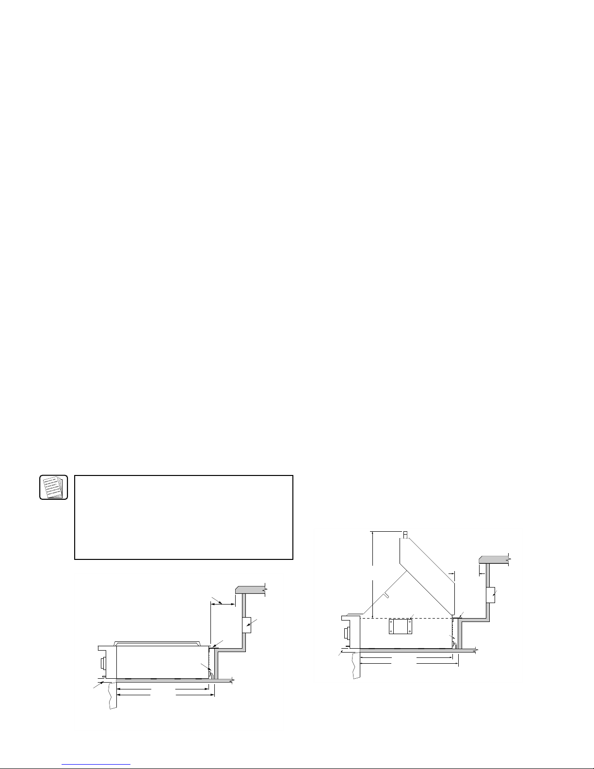
NOTE:
The rotisserie mounting bracket on the
right side of the grill chassis and the
slot in the right side finish trim must
line up for proper rotisserie motor
installation. (Selected models only)
EOSB162 Cutout Dimensions
Side View
EOG303/36/52 Cutout Dimensions
Side View
Page 3
 Loading...