

Page 1

Installation Instructions
Discovery® Built-In Refrigerator
Models: DYF30BFBPL, DYF30BFBPR, DYF30BFBSL,
DYF30BFBSR, DYF30BFTSL, DYF30BFTSR,
DYF36BFBPL, DYF36BFBPR, DYF36BFBSL,
DYF36BFBSR, DYF36BFTSL, DYF36BFTSR
Dacor Part No. 108790 Rev. C
Page 2

Table of Contents
Important Safety Instructions ......................... 1
Safety Symbols and Labels ............................ 1
General Safety Precautions ............................ 2
Product Specifications .................................... 3
Product Dimensions ........................................ 3
Installation Specifications ............................... 6
Electrical Specifications .................................. 6
Water Supply Specifications ...........................6
Preparing the Location .................................... 6
Custom Door Panel Overview ......................... 9
Custom Door Panel Construction ................. 10
Custom Grill Panel Construction ................... 12
Installation Instructions ................................. 13
Unpacking the Refrigerator ........................... 13
Moving the Unit Into the House .................... 13
Custom Panel Installation ............................. 14
Connecting the Power ................................... 16
Connecting the Water Supply .......................16
Moving the Unit into Final Position ............... 17
Leveling ......................................................... 17
Final Installation ............................................ 18
Verifying Operation ........................................ 20
Installation Checklist ..................................... 21
Before You Begin...
Important:
Installer: In the interest of safety and to minimize problems, read these installation instructions completely and
carefully before you begin the installation process. Leave these installation instructions with the customer.
Customer: Keep these installation instructions for future reference and the local electrical inspector’s use.
Customer Service Information
If You Need Help...
If you have questions or problems with installation, contact your
Dacor ® dealer or the Dacor Customer Service Team. For repairs to
Dacor appliances under warranty call the Dacor Distinctive Service
line. Whenever you call, have the model and serial number of the
appliance ready. The model and serial number are printed on the
product data label.
The product data label is located on the right door jamb. Open the
door to expose it.
Dacor Distinctive Service
(repairs under warranty only)
Phone: (800) 793-0093 ex. 2822 (U.S.A. and Canada)
Monday — Friday 6:00 a.m. to 4:00 p.m. Pacific Time
Dacor Customer Service
Phone: (800) 793-0093 ex. 2813 (U.S.A. and Canada)
Monday — Friday 6:00 a.m. to 5:00 p.m. Pacific Time
Web site: www.dacor.com
All specifications are subject to change without notice.
Dacor assumes no liability for changes to specifications.
© 2015 Dacor, all rights reserved.
Page 3
Important Safety Instructions
Important Information About
Safety Instructions
• The Important Safety Instructions and warnings in
these instructions are not meant to cover all possible
problems and conditions that can occur. Use common
sense and caution when installing, maintaining or
operating this or any other appliance.
• Always contact the Dacor Customer Service Team about
problems and conditions that you don’t understand. See
Customer Service Information.
DANGER
IMPORTANT: To prevent child entrapment and suffocation
when discarding an old appliance:
• Take off the door(s).
• Leave the racks in place so children cannot easily
climb inside.
• Cut the prongs off the power plug and discard them.
• Cut the power cable off and discard it separately from
the old appliance.
IMPORTANT: To avoid the possibility of explosion or fire,
do not store or use combustible, flammable or explosive
vapors and liquids (such as gasoline) inside or in the
vicinity of this or any other appliance.
State of California Proposition 65 Warnings:
WARNING: This product contains one or more chemicals
known to the State of California to cause cancer.
WARNING: This product contains one or more chemicals
known to the State of California to cause birth defects or
other reproductive harm.
Safety Symbols and Labels
DANGER
Immediate hazards that WILL result in severe personal
injury or death.
WARNING
Hazards or unsafe practices that COULD result in severe
personal injury or death.
CAUTION
Hazards or unsafe practices that MIGHT result in minor
personal injury or property damage.
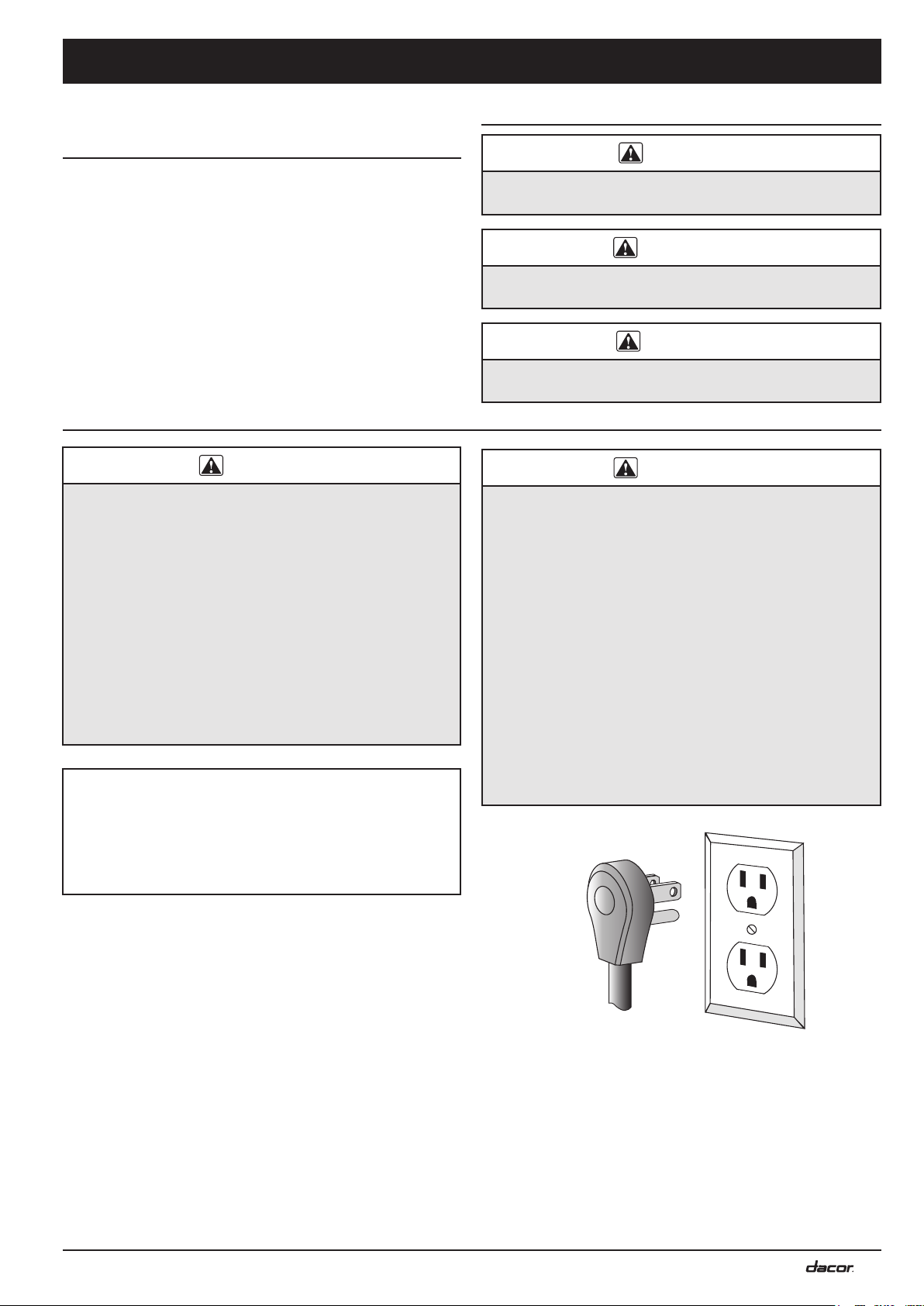
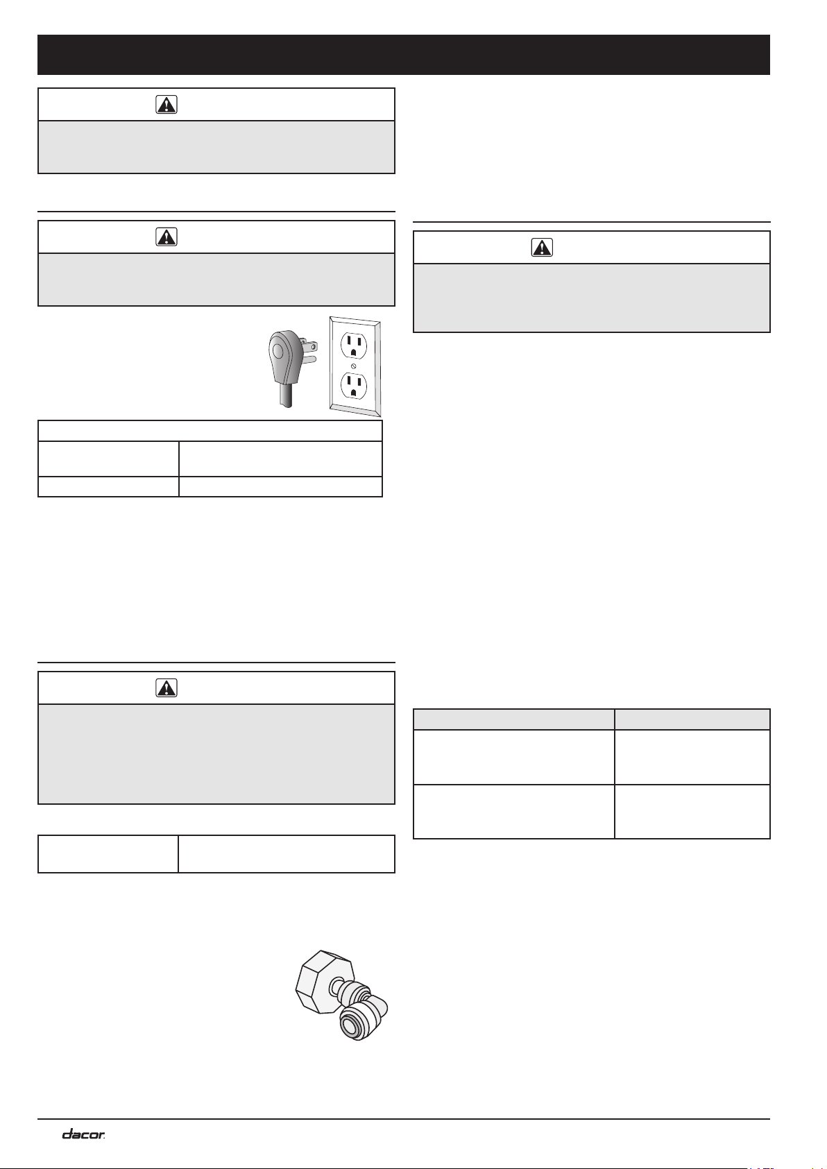
WARNING
IMPORTANT: This appliance is equipped with a three-
prong grounding electric plug for protection against
possible electric shock hazards. It must be plugged into a
dedicated, grounded, electrical outlet. If only a two-prong
electrical outlet is available, it is the responsibility of the
customer to have it replaced with a dedicated, properly
grounded three-prong electrical outlet.
• DO NOT cut or remove the third (ground) prong from
the power cord.
• DO NOT use an adapter plug.
• DO NOT use a power cord that is frayed or damaged.
• DO NOT connect the appliance to an extension cord.
• Keep the power cord away from heated surfaces.
NOTE: Use of an electrical outlet with a ground fault
interrupter (GFI) is not recommended.
Power cord with threeprong grounding plug
Grounded type
electrical outlet
READ AND SAVE THESE INSTRUCTIONS
1
Page 4
Important Safety Instructions
General Safety Precautions
WARNING - To reduce the risk of fire, electric shock, serious injury or death when using your appliance, follow basic safety
precautions, including the following:
WARNING
• If you receive a damaged product, immediately contact
your dealer or builder. Do not install or use a damaged
appliance.
• Make sure that this appliance has been properly
installed according to these installation instructions.
• Make sure you know the location of the electrical
outlet so that you know where and how to disconnect
power. Making sure the appliance is properly installed
is the responsibility of the customer.
• Refrigeration equipment and refrigerants must be
properly disposed of in a professional and appropriate
way, in accordance with the current local regulations
and laws which protect the environment. This applies
to your old appliance and to your new unit once it has
reached the end of its service life. DO NOT dispose of
the appliance in a landfill or with urban waste. Contact
local waste disposal centers for information on how to
dispose of recyclable waste.
• Take care when handling, moving, using or disposing
of the appliance to avoid damaging the refrigeration
system.
• Do not install or use outdoors or in wet conditions.
This appliance is not designed for installation in a
recreational vehicle or boat.
• Keep packaging materials away from children. Plastic
sheets and bags can cause suffocation.
• Connect this appliance to a 115 Vac, 15 Amp. circuit
that is controlled by a circuit breaker or fuse. This
appliance should have its own separate grounded
circuit.
• Do not kink or pinch the power supply cord of the
appliance. Never unplug the appliance by pulling on
the power cord. Always grip the plug firmly and pull
straight out from the electrical outlet.
• Disconnect this appliance when not in use.
• Do not install, repair, modify, or replace any part of
the appliance unless specifically recommended in
the literature accompanying it. A qualified service
technician should perform all other service.
• Before performing any type of service, disconnect the
unit from the electrical outlet or disconnect power at
the circuit breaker panel or fuse box.
• Use this appliance only for its intended purpose: the
storage of food and beverages. It is not intended for
commercial or industrial use.
WARNING
• This appliance is not intended for use by persons
(including children) with reduced physical, sensory
abilities, or lack of experience and knowledge, unless
they are properly supervised by a person responsible
for their safety. Children must be supervised for their
safety.
• Never allow anyone, including children to sit, stand or
climb on any part of the appliance, including the door.
Doing so may cause damage, serious injury or death.
• If the power cord is damaged, it must be replaced by
the manufacturer or a qualified service technician in
order to avoid a safety hazard. Do not tamper with the
controls.
• Clean this appliance regularly as instructed in the
Care and Cleaning section of the use and care
manual. Clean the ice bucket or drawer regularly.
• The appliance features a lighting system with high
intensity LED lamps. Do not stare into these lamps
when they are on to avoid possible eyesight damage.
• When the freezer is functioning, do not touch the inner
stainless steel surfaces with wet or damp hands, since
skin may stick to the very cold surfaces.
• Do not use any type of electrical equipment inside the
refrigerator or freezer compartments.
• When positioning the shelves, do not place fingers in
the shelf slide guides.
• Do not obstruct any of the vents or openings on the
appliance.
• To avoid risk of the appliance tipping over it is
mandatory to secure the appliance to the wall by
means of the two supplied anti-tip brackets.
• Do not obstruct any of the vents or openings on the
appliance.
2
Page 5
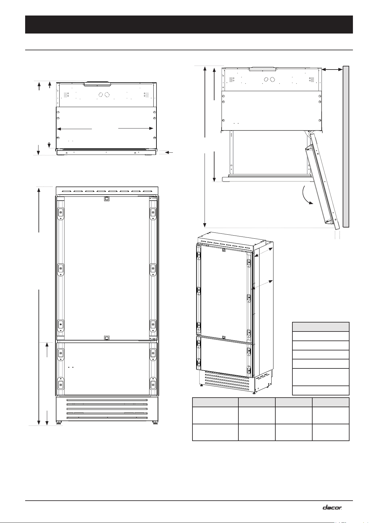
Product Specifications
A
B
C
A
B
C
28 7/8” (73.2 cm)
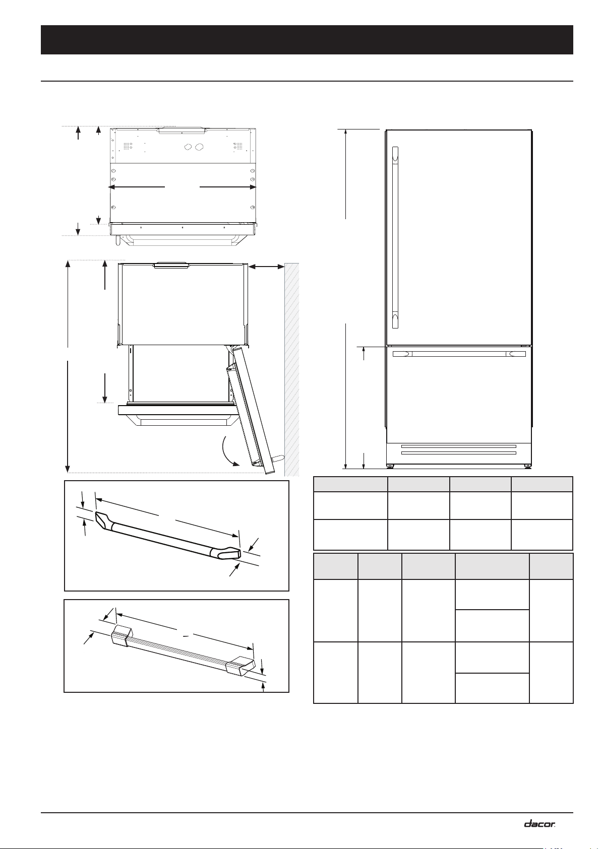
Product Dimensions: Stainless, Bottom Compressor
Models DYF30BFBSL DYF30BFBSR, DYF36BFBSL DYF36BFBSR
Depth Dimensions
2
1
3
in (58.7 cm)
in (63.8 cm)
⅛
⅛
22
25
a
7
6
C
1
B
40 in (101.6 cm)
Product tolerances: ±1/16” (±1.6 mm)
Height Dimensions
83 1/2” (212.1 cm)
7
D
Epicure handle
(standard on bottom compressor models)
F
Pro handle (optional)
Electric cord length: 90 inches (2.3 m)
1
Excludes depth of door handle.
2
For cabinet depth, with side trim removed,
subtract 3/4 in (1.9 cm).
3
For cabinet width, with side trim removed,
subtract 1/2 in (1.3 cm).
4
30-inch wide models.
105°
Model A
DYF30BFBSL
E
F
DYF30BFBSR
DYF36BFBSL
DYF36BFBSR
Handle D
Epicure
13/16 in
(2.1 cm)
E
D
1 1/2 in
(3.8 cm)
Pro
5
36-inch wide models.
6
Dimensions are with standard, Epicure style door handle
installed. Distance to side wall is required to allow door to
open 105-degrees. However, a 90-degree door opening is
sufficient to allow all drawers to open to full extension.
7
Height can be increased up to 1 inch (2.5 cm) using the
adjustable legs.
3
29 1/2 in
(74.9 cm)
35 3/8 in
(89.9 cm)
E - Refrig
Door
37 3/8 in
(94.9 cm)
37 3/4 in
(95.9 cm)
B C
52 in
(132.0 cm)
57 7/8 in
(147.0 cm)
E - Freezer
Door
25 1/2 in 4
(94.9 cm)
31 1/2 in 5
(80.0 cm)
25 15/16 in4
(65.8 cm)
31 13/16 in 5
(80.8 cm)
6
4 3/8 in
(11.2 cm)
5 1/2 in
(13.8 cm)
F
2 3/8 in
(6.0 cm)
2 1/2 in
(6.4 cm)
3
Page 6
Product Specifications
A
B
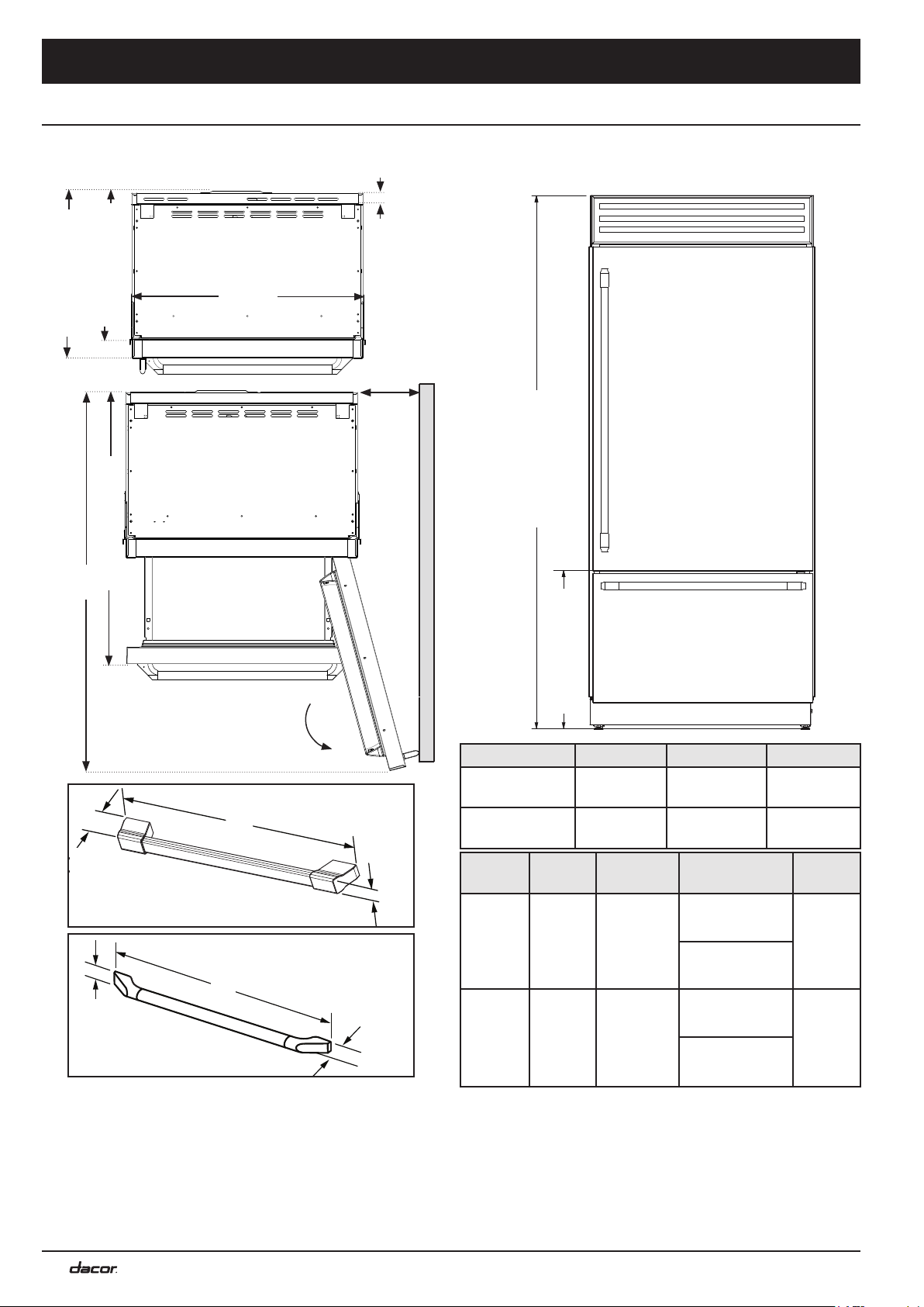
24 1/8” (61.3 cm)
Product Dimensions: Stainless, Top Compressor
Models DYF30BFTSL DYF30BFTSR, DYF36BFTSL DYF36BFTSR
Depth Dimensions Height Dimensions
2
1
in (58.7 cm)
in (63.8 cm)
⅛
⅛
22
25
1
40 in (101.6 cm)
B
3
a
3/8 in
(1.0 cm)
6
C
Product tolerances: ±1/16” (±1.6 mm)
7
83 1/2” (212.0 cm)
7
105°
E
D
F
Pro handle
(standard with top compressor models)
E
B
D
A
C
F
Epicure handle
(optional)
Electric cord length: 90 in (2.3 m)
1
Excludes depth of door handle.
2
For cabinet depth, with side trim removed,
subtract 3/4 in (1.9 cm).
3
For cabinet width, with side trim removed,
subtract 1/2 in (1.3 cm).
4
30-inch wide models.
Model A
DYF30BFTSL
DYF30BFTSR
DYF36BFTSL
DYF36BFTSR
Handle D
Epicure
Pro
5
36-inch wide models.
6
Dimensions are with standard, Pro style door handle
installed. Distance to side wall is required to allow door to
open 105-degrees. However, a 90-degree door opening is
sufficient to allow all drawers to open to full extension.
7
Height can be increased up to 1 inch (2.5 cm) using the
adjustable legs.
13/16 in
(2.1 cm)
1 1/2 in
(3.8 cm)
3
29 1/2 in
(74.9 cm)
35 3/8 in
(89.9 cm)
E - Refrig
Door
37 3/8 in
(94.9 cm)
37 3/4 in
(95.9 cm)
B C
52 in
(132.0 cm)
57 7/8 in
(147.0 cm)
E - Freezer
Door
25 1/2 in 4
(94.9 cm)
31 1/2 in 5
(80.0 cm)
25 15/16 in4
(65.8 cm)
31 13/16 in 5
(80.8 cm)
6
4 5/8 in
(11.7 cm)
5 3/4 in
(14.6 cm)
F
2 3/8 in
(6.0 cm)
2 1/2 in
(6.4 cm)
4
Page 7
Product Specifications
Product Dimensions: Panel Ready, Bottom Compressor
Models DYF30BFBPL DYF30BFBPR, DYF36BFBPL DYF36BFBPR
Depth Dimensions
2
1
)1
in (56 cm)
3
1/8
22
24 1/8 in (61 cm)
a
B
in (3.81 cm)
1/2
1
Height Dimensions
5
Product tolerances: ±1/16” (±1.6 mm)
39 in (99.2 cm
Depth Dimensions
105°
22 1/8 in
Depth
4
C
1 1/2 in
Door
Thickness
in (212.1 cm)
½
83
24 1/8 in
Depth
Depth Dimensions
DYF 30 & 36
Refrigerator Only:
22 1/8 in
Door Only Depth:
5
1 1/2 in
Refrigerator +
Door:
in (72.1 cm)
⅜
28
Model A
DYF30BFBPL
DYF30BFBPR
DYF36BFBPL
1
Excludes depth of custom panel and door handle.
2
For cabinet depth, with side trim removed, subtract 3/4 in (1.9 cm)
3
For cabinet width, with side trim removed, subtract 1/2 in (1.3 cm)
4
Distance to side wall is required to allow door to open 105 degrees. Does not include custom panel thickness and door
DYF36BFBPR
3
29 1/2 in
(74.9 cm)
35 3/8 in
(89.9 cm)
Electrical cord length: 90 in (2.3 m)
24 1/8 (+ padding)
B C
52 in
(132.0 cm)
57 7/8 in
(147.0 cm)
2 1/8 in
(5.3 cm)
3 1/8 in
(7.9 cm)
handle depth. However, a 90-degree door opening is sufficient to allow all drawers to open to full extension.
5
Height can be increased up to 1 inch (2.5 cm) using the adjustable legs.
4
5
Page 8
Installation Specifications
WARNING
Observe all governing codes and ordinances during
planning and installation. Contact your local building
department for further information.
Electrical Specifications
WARNING
Electrical and grounding connections must comply with the
applicable portions of the national electrical code and/or
other local electrical codes.
This appliance comes with an
electrical cord with a three-prong
grounding plug for a 115 Vac, 15
Amp. power supply. Plug it into a
115 Vac, three-prong, grounding
electrical outlet only.
Electrical Requirements
Electrical Circuit
Requirements:
Total Connected Load: See product data label.
15 Amp. 115 Vac, 60 Hz.
dedicated, grounded, circuit.
Circuit Requirements
The wiring from the electrical outlet shall be connected to
a circuit protected by a 15 or 20 Amp. circuit breaker or
time delay fuse, installed by a licensed electrician. Do not
use an outlet that can be turned off by a switch. Using an
electrical outlet with a ground fault interrupter (GFI) is not
recommended.
Water Supply Specifications
WARNING
The built-in water filter cannot be used to treat water that
is not suitable for human consumption. Do not connect this
appliance to a water supply that is microbiologically unsafe
or of unknown quality without adequate disinfection.
Systems certified for cyst reduction may be used on
disinfected water that may contain filterable cysts.
Water Supply Requirements
Water Supply
Pressure:
• The appliance is provided with a fitting for connection
to a 1/4-inch polyethylene water line. The customer
must provide the water line and any fittings required
to connect the water line to the
household water supply.
• The water line must be long enough
to provide enough slack to allow the
refrigerator to be moved for floor
cleaning and servicing, without the
need to first disconnect the water
line.
25 to 73 p.s.i.
(0.17 MPa to 0.50 MPa)
• Unless a whole house filtration system is installed,
the provided water filter cartridge, should be installed
according to the Use and Care Manual.
• Turn OFF the ice maker using the
water supply valve is turned off. The
the ice maker is on.
ICE key
ICE key
whenever the
is lit when
Preparing the Location
WARNING
Follow all cabinet dimensions shown on the following
pages to insure safe operation. All minimum product
dimensions must be met. Dimensions shown provide the
minimum required clearances.
• Your Dacor built-in refrigerator can be installed in a
cabinet opening (see facing page) or at the end of a
cabinet run, using a custom side panel to cover the
exposed side (see page 8).
• Carefully check the location where the appliance is to be
installed. Put it in a location with convenient access. The
power supply shall meet the Electrical Specifications.
Also, the utilities need to be installed close by in a
cabinet adjacent to the location selected so that the
power plug can be disconnected and the water supply
shut off without removing the appliance from the cutout.
• The location should allow the refrigerator door
and freezer drawer to open freely. See Product
Dimensions.
• For best performance, place the refrigerator away from
sources of heat such as cooking appliances, household
heating outlets or other sources of heat.
• Do not install the appliances in a location where the
water line could freeze.
• The floor must be capable of supporting the weight of
the appliance.
Model Weight
DYF30BFBPL, DYF30BFBPR
DYF30BFBSL, DYF30BFBSR
DYF30BFTSL, DYF30BFTSR
DYF36BFBPL, DYF36BFBPR
DYF36BFBSL, DYF36BFBSR
DYF36BFTSL, DYF36BFTSR
• The floor must be solid, level and all cutout surfaces
must be at right angles.
• In the interest of safety, the surrounding cabinet must
have sufficient material for attachment of the anti-tip
brackets in the areas shown in the cutout diagrams on
the following pages.
• Plan the installation so that the appliance can be
removed easily if service is required. Dacor is not
responsible for additional service costs charged for
removal of customer installed molding or decorative
panels to allow access for servicing the refrigerator.
606 lb (275 kg)
650 lb (295 kg)
• The water line must be routed so that no part of it is
located in areas that will fall below freezing.
6
Page 9

Installation Specifications
Refrigerator
Side trim attached to
surrounding cabinet
Full Built-in Installation
The refrigerator is shipped with the side trim pieces installed.
These trim pieces have screw holes that allow the unit to
attach to the surrounding cabinets or side panels for a builtin installation using 1/8” diameter wood screws.
These trim pieces may be removed if:
• the cabinet depth is shallow
• a side panel is not required
Refer to the tables on this page for additional information.
Minimum Cabinet Depth (all models)
These depth dimensions allow for minimum ventilation
requirements at the rear of the appliance.
Configuration Minimum Cabinet Depth
Side trim installed
Without side trim installed
.
23 7/8 in (60.6 cm)
23 1/8 in (58.7 cm)
Cutout tolerances: +1/16” -0” (+1.6 mm)
5 1/2 in (14 cm) 5 1/2 in (14 cm)
4 in (10 cm)
A A
B
C
E W E W
4 in (10 cm)
Full Built-In Installation
Cabinet Cutout (Front View)
A: Areas to be left clear for the anti-tip brackets
E: Recommended electrical outlet locations
W: Recommended water supply locations
Models
(B) Cabinet
Width for Built-in
Installation
1
(C) Minimum
Cabinet Height
DYF30BFBPL
DYF30BFBPR
DYF30BFBSL
29 5/8 in (75.2 cm) 84 in (213.4 cm)
DYF30BFBSR
DYF30BFTSL
DYF30BFTSR
29 5/8 in (75.2 cm) 84 in (213.4 cm)
DYF36BFBPL
DYF36BFBPR
DYF36BFBSL
35 1/2 in (90.2 cm)
84 in (213.4 cm)
DYF36BFBSR
DYF36BFTSL
DYF36BFTSR
35 1/2 in (90.2 cm)
84 in (213.4 cm)
2
Full Built-in Installation (Top View)
1
Installation inside a cabinet of this width allows the
refrigerator trim to be attached directly to the surrounding
cabinets. This width is the minimum that must be kept when
the side trim is removed to allow for proper ventilation.
2
Installation in cabinets of this height requires that the back
of the cabinet be ventilated through the top. Otherwise, a
2-inch increase in cabinet height is required for adequate
ventilation.
7
Page 10

Installation Specifications
Support board
cabinet
Side trim attached
to
side panel
side panel
cabinet
Built-in Installation with Custom Side Panel
• A custom side panel is necessary when the refrigerator
is installed at the end of a cabinet run. The side panel
covers the side of the refrigerator chassis.
• The required depth of the side panel is the same as the
depth of the cabinet on the opposite side of the unit.
• A support board is mounted to the wall behind the
refrigerator. It will act as a bracket to attach the custom
side panel to the wall behind the refrigerator.
• The refrigerator is shipped with the side trim pieces preinstalled. These trim pieces have screw holes that allow
the unit to attached to the cabinet and side panel using
1/8” diameter wood screws.
• See tables on this page for cutout dimensions.
5 1/2 in (14 cm) 5 1/2 in (14 cm)
4 in (10 cm)
C
Cutout tolerances: +1/16” -0 (+1.6 mm)
A A
4 in (10 cm)
Cabinet
B
Custom Side Panel
Built-in Installation with Custom Side Panel
E W
Cabinet Cutout with Side Panel (Front View)
A: Area to be left clear for the anti-tip brackets
E: Recommended electrical outlet location
W: Recommended water supply location
Minimum Cabinet Depth: 23 7/8 in (60.6 cm)
Models
DYF30BFBPL
DYF30BFBPR
DYF30BFBSL
DYF30BFBSR
DYF30BFTSL
DYF30BFTSR
DYF36BFBPL
DYF36BFBPR
DYF36BFBSL
DYF36BFBSR
DYF36BFTSL
DYF36BFTSR
(B) Cabinet
Width for Built-In
Installation
29 5/8 inches
(75.2 cm)
29 5/8 inches
(75.2 cm)
35 1/2 inches
(90.2 cm)
35 1/2 inches
(90.2 cm)
1
(C) Minimum
Cabinet Height
84 inches
(213.4 cm)
84 inches
(213.4 cm)
84 inches
(213.4 cm)
84 inches
(213.4 cm)
2
Built-in Installation with Custom Side Panel (Top View)
8
1
Installation inside a cabinet of this width allows the
refrigerator trim to be attached directly to the surrounding
cabinets.
This width is the minimum that must be kept when the side
trim is removed to allow for proper ventilation.
2
Installation in cabinets of this height requires that the back
of the cabinet be ventilated through the top. Otherwise,
a 2-inch height increase in cabinet height is required for
adequate ventilation.
Page 11

Supplied grill
Custom panel
Installation Specifications
Custom Door Panel Overview
Models DYF30BFBPL, DYF30BFBPR, DYF36BFBPL
and DYF36BFBPR Only
• Custom overlay panels and handles for the above
models allow you to blend the exterior of your
refrigerator into your overall kitchen décor.
• The panels are mounted and adjusted using the
supplied mounting hardware.
• The mounting brackets attach to your custom panels.
The brackets slip over the mounting studs installed on
the front of the refrigerator door and freezer drawer. See
the following pages for panel and mounting dimensions
and specifications.
Panel
Mounting
Studs
Mounting
Brackets
Handle Specifications
Before installing the custom panels, you must first install the
door/drawer handles.
• With custom panel models, you
have the advantage of being able
to select a handle style that meets
your own personal taste. Dacor
recommends handles with larger
D-style pulls. Any handle designed
for use with an appliance should
produce satisfactory results.
• Handles are not provided with
custom panel models. Selected
handle kits are available through
your Dacor dealer. Dacor does not
advise the use of single pull knobs.
• Most handle kits do not include
the necessary mounting screws
because screw lengths varies
with panel thickness.
• The panel craftsman needs to select
and purchase the required fasteners for the installation.
The screw heads must be countersunk into the panel to
prevent interference during depth adjustment (page 15).
D-Style Handle
36 inch
MAX
Customer
Supplied
1/8-inch gap
between panels
Mounting Hardware for Custom Panel
Custom Grill Cover
The refrigerator grill does not come with hardware for
attaching a custom grill panel. However, it is possible to
create a custom panel for the grill by using the dimensions
on page 12, to avoid loss of air flow. The custom panel
attaches by drilling holes in the existing magnetically
attached (white) grill and using wood screws to secure it.
Handle
Countersunk
screw
Custom
panel
Appliance
door/drawer
Handle Installation for Units with
Custom Door Panels (Top View)
9
Page 12

Installation Specifications
C
L
Custom Door Panel Construction
Models DYF30BFBPL, DYF30BFBPR, DYF36BFBPL
and DYF36BFBPR Only
The door and freezer panels can extend above and
below the edges of the unit.
The dimensions can be adjusted according to your
unique and specific requirements, cabinetry setup, and
design style.
• Use a 1/16” drill bit for all holes.
• Be careful not to penetrate the front finish.
Refrigerator Door Panel
1/4 in (0.65 cm)
1 3/8 in
(3.4 cm)
Maximum
Weight
Panel
Thickness
B
Panel Weight/Thickness Specifications
Refrigerator Door Freezer Drawer
51 lb (23 kg) 25 lb (11 kg)
3/4 in (18 mm) min.
1 1/8 in (28 mm)
max.
A
B
1/4 in (0.65 cm)
3/4 in (18 mm) min.
1 1/8 in (28 mm)
max.
Tolerances: ±1/16” (±1.6 mm)
Freezer Drawer Panel
1 3/8 (3.4cm)
26 in (66 cm)
45 3/4 in (116.3 cm)
50 1/8 in (127.3 cm)
6 1/4 in
(15.7 cm)
An 1/8” gap between panels is recommended
a
BB
54 3/4 in (139 cm)
C
L
Refrigerator Door
DYF30BFBPL
DYF30BFBPR
a 29 3/8 in ( 74.7 cm) 35 1/4 in (89.7 cm)
B 13 1/2 in (34.2 cm) 16 1/2 in (4.17 cm)
DYF36BFBPL
DYF36BFBPR
10
4 in (10 cm)
15 ⅛ in (38.2 cm)
20 in (50.8 cm)
1/2 in (1.3 cm)
C
Freezer Drawer
DYF30BFBPL
25 in MAX (63.5 cm)
C
DYF30BFBPR
a 29 3/8 in ( 74.7 cm) 35 1/4 in (89.7 cm)
B 13 1/2 in (4.17 cm) 16 1/2 in (4.17 cm)
C 11 in (27.95 cm) 14 in (35.45 cm)
DYF36BFBPL
DYF36BFBPR
Page 13

Installation Specifications
Details of the bracket hardware used on the panels.
Install the brackets according to the templates on
page 10:
• Mounting Brackets
• Leveling Bracket (refrigerator)
• Leveling Bracket (freezer)
B - Refrigerator door (top)
leveling bracket
A - Mounting bracket
A 6 pc
B 1 pc
Mounting Hardware
C - Freezer drawer
(bottom) leveling bracket
A 4 pc
C 2 pc
Freezer Panel with Hardware
Refrigerator Panel with Hardware
11
Page 14

Installation Specifications
Drill hole in supplied grill,
4 places
Customer supplied
screw, 4 places
Custom panel
8 1/2”
(21.6 cm)
A
C
D
E
B
Custom Grill Panel Construction
Optional for models DYF30BFBPL, DYF30BFBPR,
DYF36BFBPL and DYF36BFBPR.
Construct the custom grill panel to the dimensions below.
Tolerances: ±1/16” (±1.6 mm)
DYF30BFBPL
DYF30BFBPR
29 3/8” (74.7 cm) 35 1/4” (89.7 cm)
A
27 7/8” (708 mm) 27 7/8” (708 mm)
B
13/16” (20 mm) 13/16” (20 mm)
C
D
E
5/8” (15 mm) 5/8” (15 mm)
15/16” (25 mm) 15/16” (25 mm)
Grill Panel Weight/Thickness
Maximum Weight
Panel Thickness
DYF36BFBPL
DYF36BFBPR
Specifications
10 lb (4.5 kg)
3/4” (18 mm) min.
1 1/8” (28 mm) max.
12
Page 15

Installation Instructions
B
A
A
C
D
Unpacking the Refrigerator
1. Wait to remove the packing materials and tape from the
inside and outside of the unit until it is moved into the
house. It is best to leave the unit on the shipping pallet
until it is positioned in front of the cabinet cutout.
2. Verify that all required components have been provided.
Inspect the unit for shipping damage (including cosmetic
damage). If any item is missing or damaged, please
contact your dealer immediately. Do not install a
damaged or incomplete appliance.
Parts included
• 1/4” to 3/4” self-locking water supply line adapter
• Anti-tip bracket kit with fasteners
• Water filter
• Ice scoop
• Cleaning cloth
• Cleaning sponge
• User manuals
• Grill (bottom grill units only, ships in place on some
models, on others, it is taped to the back or side of the
unit)
• Kick panel (top grill units only, taped to back or side of
unit)
• Trim covers, white (taped to the back or side of the unit)
• Custom panel mounting kit - for model numbers ending
in PL and PR only
• Vinyl door trim - for model numbers ending in PL and
PR only
Tools/parts required for installation (not provided)
• 1/4” O.D. plastic water line
• Fittings necessary to connect water line to household
water supply
• 1/8 inch diameter wood screws (required if side trim will
be attached to surrounding cabinets or if custom side
panels will be used, 5 required per side)
• Phillips head screwdriver
• Electric drill
• 1/16” (2 mm) drill bit for wood
• 3/8” (8 mm) bit for walls
• Crescent wrench
Make sure you have everything necessary for proper
installation before proceeding.
Moving the Unit Into the House
WARNING
• TIP OVER HAZARD: This appliance is large, heavy
and tips easily when not installed. Always transport
in an erect position if possible. If this is not possible,
transport laying on the back side. Keep doors taped
shut during transport.
• Move and install with a minimum of two persons.
• Be very careful to avoid floor damage. Delicate flooring
should be protected with plywood, hard cardboard, or
similar material.
1. Before transporting the appliance, check access to the
location where it will be installed (door size, maneuvring
space in stairwells, etc.).
2. Use a dolly to transport. Once at the final location,
remove the appliance from the pallet as instructed
below. The unit is equipped with rollers to allow it to be
pushed into place after connection of the water supply
and power.
3. Take a crescent wrench, and remove the four (4) screws
bolted to the pallet A .
4. Lift and remove the two (2) L- brackets from the rear of
the refrigerator B .
5. Lift and remove the two (2) L- brackets on the front of
the refrigerator D .
• If necessary, use a crescent wrench to loosen the bolts
C . Turn twice to release, then retighten. Do not
overtighten.
6. With the help of at least one additional person, remove
the refrigerator from the pallet.
13
Page 16

Installation Instructions
Custom Panel Installation
Models DYF30BFBPL, DYF30BFBPR, DYF36BFBPL
and DYF36BFBPR Only
NOTE: Before proceeding with door panel installation, all
mounting brackets must be installed according to the panel
specifications starting on page 9.
Handle Installation
Install the door handles on the custom panels according
to the handle installation instructions prior to custom panel
installation. Reference the Handle Specifications on
page 9.
Preparing for Installation
1. Make sure that all tape has been removed from the
door.
2. Hand thread the ten (10) set screws A . Insert the
hex end first, and thread each set screw as deep as
possible.
3. Hand thread the ten (10) adjustment studs B . Each
stud will grip the panel hardware, so thread the stud
only until half remains above the surface.
A Set screw
Freezer Drawer Panel Installation
1. Make sure that all tape has been removed from the
drawer.
2. Place washers on two (2) of the hex bolts. Hand thread
the two bolts into the holes in the bottom of the freezer
drawer. Thread each bolt half way.
3. Attach the freezer drawer panel to the freezer drawer
by hooking the four (4) brackets on the panel over the
adjustment studs (previously installed).
Wait to make final adjustments until the refrigerator door
panel is in place.
(insert hex end first)
B Adjustment stud
Freezer Drawer
Bottom of Freezer Drawer
Freezer Drawer Panel
14
Page 17

Installation Instructions
Refrigerator Door Panel Installation
1. Attach the refrigerator door panel to the refrigerator
face by hooking the six (6) brackets on the back of the
custom panel over the adjustment studs on the door
face. During installation, the adjustment brackets on the
top of the panel need to be inserted into the slots at the
top of the door face.
Align the refrigerator door panel vertically and
horizontally by adjusting the bolts on the top of
the refrigerator door face using the hex wrench.
Top of refrigerator door
To Adjust the Depth of the Panels
1. Push the magnetic seal aside on the back side of the
refrigerator door face and the freezer drawer face to
expose the adjustment holes.
• There are 3 sets of adjustment holes on each side of the
refrigerator door and 2 sets of holes on each side the
the freezer drawer. See diagrams below.
2. Insert the hex wrench into the holes labeled
ADJUSTMENT and turn to adjust the panel depth.
3. Lock the the panel into place by inserting the hex
wrench into the holes labeled LOCK and turning each
set screw clockwise until it stops. See diagrams below.
2. Place a washer on one of the hex bolts. Hand thread
it into one of the holes in the top of refrigerator door.
Thread it half way. Do the same for the other hole.
Top of refrigerator door
Final Panel Alignment
1. Align the freezer drawer panel vertically and horizontally
by adjusting the bolts on the underside of the freezer
drawer face using the hex wrench (included).
IMPORTANT
To ensure the doors shut correctly, pull the magnetic seals
back into position so that they are straight.
Magnetic seal
Panel Depth Adjustment (Refrigerator)
Magnetic seal
Bottom of
freezer drawer
Panel Depth Adjustment (Freezer)
15
Page 18

Installation Instructions
EW
E W
W
ON/OFF
Back of
unit
Connecting the Power
1. Unwind the power cord and connect it directly to the
electrical outlet.
2. Make sure the appliance is
in Stand-by mode (Standby is flashing on the control
panel display) and that all
lights are off. If the unit is
not in Stand-by mode, touch the ON/OFF key to turn it
off.
3. Also make sure the ICE light on the control panel is off. If
it is on, touch the ICE key to turn it off.
Connecting the Water Supply
Units with grill on bottom:
1. Connect one end of a 1/4 inch O.D. polyethylene water
line to the household water supply valve.
2. Hold the other end of the water line over a bucket. Turn
on the water valve to flush out impurities and air. When
the water is clear, turn off the valve.
3. Connect the water supply fitting to the back of the
refrigerator as shown below. Make sure it is tightened
firmly into place, but do not overtighten.
4. Insert the end of the water line into the self locking water
supply fitting as shown below. Push in until it stops.
3. Insert the water supply line into the water connection
access hole on the back of the unit as shown.
Water connection
access hole
Back of unit
4. Reach through the opening on the bottom front of the
unit, and pull the end of the water line out of the front.
Hold it over a bucket. Turn on the water valve and flush
out impurities and air. When the water is clear, turn off
the valve.
5. Insert the end of the water line into the self locking
water supply fitting as shown directly below. Push it
until the line stops.
6. Turn the water valve ON and check for leaks. Tighten
connections as needed.
Water
line
Front of
unit
Water
supply fitting
5. Turn on the water valve and check for leaks. Tighten
connections as necessary.
Water
line
Units with grill on top:
1. Reach under the bottom front of the unit and connect
the water supply fitting to the water supply connection,
as shown below. Tighten it firmly into place, but do not
overtighten.
2. Connect one end of a 1/4 inch O.D. plastic water line to
the household water supply valve.
Front of unit
Water supply
connection
Water line:
bottom grill
models
Water line: top
grill models
Power
cord
16
E = Electrical Connection W = Water supply connection
Utility Connections (Top View)
Page 19

Installation Instructions
Moving the Unit into Final Position
1. If a custom side panel will be installed on one side of
the unit, attach the required support board to the wall
prior to pushing the unit into position (see page 18).
2. Before moving the unit to its final position, make sure
the front leveling legs are in the up position. Using a
crescent wrench, turn the legs A (see diagram below)
to the right until they clear the floor. On some bottom
grill models, you may need to remove the grill to access
the legs.
WARNING
• Be careful when installing or removing the appliance
to reduce the likelihood of damage to the floor, to the
power cord and the water supply line.
• After moving the unit into place, be sure to lower the
front leveling legs to help support the refrigerator. See
Leveling.
3. Remove the trim covers taped to the back or side of the
unit. On some models the ventilation grill or kick panel
is taped to the unit and needs to be removed before
performing the following steps.
If the unit is to be installed without the side trim attached
(the unit will not be attached to the surrounding
cabinets):
4. Remove the screws that hold the side trim pieces in
place.
5. Slowly and gently push or walk the unit backward into
place. As you do this, have someone gently pull the
water supply line’s slack and power cord’s slack through
the access holes into the adjacent cabinetry. This will
help prevent the unit from landing on the line and cord.
Leveling
Use the leveling feet to level the appliance all directions. On
units with a bottom grill, make sure that the grill is removed
before proceeding.
1. Adjust the height of the front legs A by turning them
with a crescent wrench.
2. Adjust the height of the rear wheels by turning the
adjusting bolts B located on the front of the unit.
B
B
A
A
IMPORTANT: The leveling legs must contact the floor to
properly support the weight of the refrigerator. The front
rollers are for moving the refrigerator and not for permanent
support.
3. Some units have a plastic coating over the grill or kick
panel. Remove any plastic coating on the grill or kick
panel (depending on the model). Install the grill/kick
panel on the bottom of the unit, behind the freezer
drawer. The grill/kick panel is held in place by magnets.
continued...
Side Trim
Showing Screws
Grill Installation -
Bottom Grill Models
Kick Panel Installation -
Top Grill Models
17
Page 20

Installation Instructions
Support board
cabinet
Side trim attached
to
side panel
side panel
cabinet
Final Installation
Attach Unit to Cabinets (optional)
1. Drill pilot holes (for the wood screws) through the side
trim and into the adjoining cabinet(s).
2. Attach the refrigerator to the adjacent cabinets using
1/8-inch wood screws.
• If a custom side panel will be installed, see the side
panel attachment instructions.
3. After tightening the screws, open and close the
refrigerator door and freezer drawer to check for
interference.
Attach Custom Side Panel (optional)
IMPORTANT: Dacor is not responsible for additional service
costs charged for removal of customer installed molding or
decorative panels required to service the refrigerator.
1. Attach the side panel to the support board in back and
attach to the refrigerator trim piece in front.
2. See diagrams below.
Side panel
Side panel
support board
Refrigerator
side trim
Pilot Holes in Side Trim
Built-in Installation with Side Panel
Built-in Installation with Side Panel (Top View)
Refrigerator
Side trim attached to
surrounding cabinet
18
Full Built-in Installation (Top View)
Page 21

Installation Instructions
Attach Trim Covers (optional)
1. The trim covers cover the inner surface of the side trims
and the screws heads.
2. To install the side trim pieces, open the refrigerator door
and freezer drawer to access the inner surfaces of the
side trims.
3. Slide the trim covers into place, as shown, until they
“click” into place. See diagrams below.
4. Close the doors.
Refrigerator
side trim
Trim
cover
Anti-tip Bracket Installation
It is mandatory to install the anti-tip brackets (included)
on the upper part of the refrigerator and secure it to the wall.
The method of installation depends on the appliance model.
Anti-tip Bracket Installation for Bottom Grill
Models
Models DYF30BFBSL DYF30BFBSR, DYF36BFBSL
DYF36BFBSR, DYF30BFBPL DYF30BFBPR,
DYF36BFBPL DYF36BFBPR
Read and familiarize yourself with the diagrams
below before beginning the following bracket
installation.
1. Place a anti-tip brackets (included) on the top of the
appliance.
2. Line up the bottom slot in the bracket with the screw
holes on the top of the appliance. See diagrams below.
3. Use the slot on the bracket to mark the hole position on
the wall.
4. Remove the bracket and drill a 3/8” (8 mm) hole in the
wall at the point marked in step 2. Insert the provided
wall anchor into the wall.
5. Reposition the bracket and attach it to the top of the
refrigerator. Use two (2) of the machine screws in the
anti-tip bracket kit (included).
6. Attach the bracket to the wall with one (1) wood screw.
Repeat the above steps for the other anti-tip bracket.
Trim Cover Installation
Refrigerator
side trim
Bottom Grill Models
Wall
Top of refrigerator
Anti-Tip Parts Detail
Wall
Top of refrigerator
Anti-Tip Finished Install
Trim Cover Installation (Top View)
Trim cover
19
Page 22

Installation Instructions
Anti-tip Bracket Installation for Top Grill
Models
Models DYF30BFTSL DYF30BFTSR, DYF36BFTSL
DYF36BFTSR
Read and familiarize yourself with the diagrams
below before beginning the following bracket
installation.
1. Remove the sheet metal screw located at the top back
of the appliance, located inside the chassis, on the right
side (see diagrams below).
2. Use the screw removed in step 1 to loosely attach the
anti-tip bracket to the appliance. Push the back of the
bracket up against the wall.
3. Use the slot on the bracket to mark the hole position on
the wall.
4. Rotate the bracket out of the way, and drill a 3/8” (8 mm)
hole in the wall at the point marked in step 3.
5. Insert the wall anchor into the wall.
6. Reposition the bracket against the wall and tighten the
sheet metal screw.
7. Attach the bracket to the wall using a wood screw.
8. Repeat the above steps for the other anti-tip bracket.
Top Grill Models
Wall
Verifying Operation
1. Read the use and care manual completely before using
the refrigerator.
2. When the appliance is first plugged in, Stand by should
appear on the display.
3. Turn to the Switching On and Off in the Operation
section of the use and care manual for first time start up
instructions.
4. After turning on the refrigerator turn to Using the Ice
Maker for the First Time on the following page of
the use and care manual for important information on
setting up the ice maker.
IMPORTANT
Adjustment of the control panel settings is not possible
when the refrigerator is starting up for the first time.
Changes made to the control panel settings may not be
saved until the compartments have reached operating
temperature.
If the appliance fails to operate properly:
• Verify that power is supplied to the electrical outlet and
that the appliance is plugged in.
• Check all plumbing connections.
• Check for kinks in the water supply line.
• If the appliance still does not work, contact
Dacor Distinctive Service at (800) 793-0093 ex. 2822
• Do not attempt to repair the appliance yourself. If you
need service, be sure to
• have the model and serial numbers available when you
call. See the inside cover for location.
Dacor is not responsible for the cost of correcting problems
caused by a faulty installation.
Top of
refrigerator
Anti-Tip Parts Detail
Wall
Top of
refrigerator
Anti-Tip Parts Detail
20
Existing
screw
Page 23

Installation Instructions
Installation Checklist
WARNING
• To ensure a safe and proper installation, the following
checklist should be completed by the installer to
ensure that no part of the installation has been
overlooked and the unit is working properly.
• Proper installation is the responsibility of
the homeowner. The importance of proper
installation of your Dacor appliance cannot be
overemphasized.
□ Has the unit been inspected for cosmetic damage?
□ Has the water supply line been properly installed
according to specifications and checked for leaks?
□ Is the unit properly aligned with the adjacent cabinets?
□ Do all doors, drawers and shelves operate smoothly,
without interference?
□ Has all packaging, tape, and literature been removed
from inside and outside of the appliance?
□ Is the power cable connected to a three-prong grounded
electrical outlet that meets the electrical specifications?
□ Has the unit been properly leveled?
□ Have the anti-tip brackets been properly installed?
□ Has proper operation been verified?
□ Has the warranty been activated on-line or the warranty
card filled out and mailed?
21
Page 24

Dacor ● 14425 Clark Avenue, City of Industry, CA 91745 ● Phone: (800) 793-0093 ● Fax: (626) 403-3130 ● www.dacor.com
 Loading...