

Page 1
DHDxx
Doc #: PGH-DHD.01 Revised 19 Sept 2018 Page 1 of 3
All tolerances: ±¹/₁₆” (±1.6 mm) unless otherwise stated.
Modernist 30”, 36", 48" Wide
General Specifications
All Models: DHD30/36/48
Features Description
Blower Speeds Four (4)
Filters Baffle style, dishwasher safe
Exhaust(s) 8” duct diameter
Total
Connected
Load
Lights
Individual Models: DHD30/36/48
Components 48” 36” 30”
30”, 36”: 120V, 60 Hz, 15 Amp (actual load 3.3 Amp, 6
Amp initial surge)
48”: 120V, 60 Hz, 15 Amp (actual load 6.1 Amp, 12 Amp
initial surge)
Dimmable LED: PAR16 E26/27; 120V, 7.5W (75W Max.
other bulbs)
Wall Hood
• Observe all local ordinances during planning and installation.
Contact your local building department for details.
• This unit must be installed according to its installation instructions.
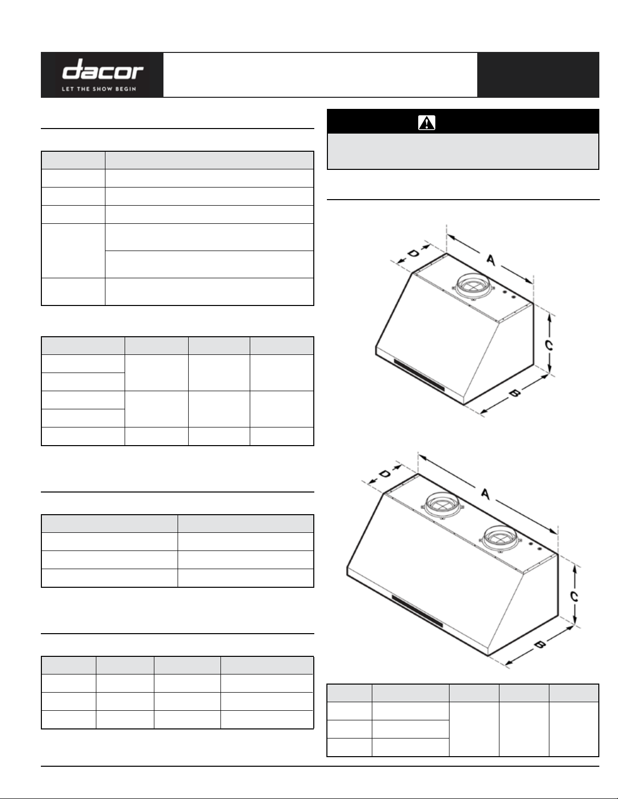
Dimensions
Single Blower DHD30/36
PLANNING
WARNING
GUIDE
Lights
4 3 2
Filters
Blowers
2 1 1
Exhaust Vents
Blower Rating 1200 CFM 600 CFM 600 CFM
Weight Specifications
Individual Models: DHD30/36/48
Model Weight
30 53 lbs (24 kg)
36 57 lbs (26 kg)
48 77 lbs (35 kg)
Ventilation
Individual Models
Dual Blower DHD48
Model Top Vent Rear Vent Rotatable Fan
30 X X X
36 X X X
48 X X X
All specications subject to change without notice. www.dacor.com Ph. 800.793.0093
Model A B C D
30 29 ” (75.9 cm)
36 35 ” (91.1 cm)
48 47 ” (121.6 cm)
24”
(61 cm)
18”
(45.7 cm)
11 ”
(30.2 cm)
Page 2
DHDxx
All tolerances: ±¹/₁₆” (±1.6 mm) unless otherwise stated.
Page 2 of 3
Modernist 30”, 36", 48" Wide
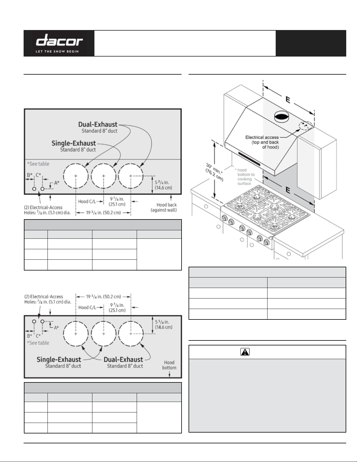
Wall Hood
Electrical/Duct Connections
Connect wiring/ducting through the top or rear of the hood. Before
installing the hood, mark the access holes per these diagrams.
Top Connections—All Models
PLANNING
GUIDE
Cabinet Layout Dimensions
Dimension: Top Electrical/Ducting Holes
Model A B C
48 1 ½ in. (3.81 cm) 5 in. (12.7 cm)
3 in. (7.62 cm)36 1 ½ in. (3.81 cm) 4 ½ in. (11.43 cm)
30 1 ½ in. (3.81 cm) 5 ½ in. (13.97 cm)
Rear Connections—All Models
Dimension: Rear Electrical/Ducting Holes
Model A B C
48 1 in. (2.54 cm) 5 in. (12.7 cm)
3 in. (7.62 cm)36 1 in. (2.54 cm) 4 ½ in. (11.43 cm)
30 1 in. (2.54 cm) 5 ½ in. (13.97 cm)
Min. Width of E (Upper-Cabinet Cutout, Appliance Width)
DHD Model E
30 30 in. (76.2 cm)
36 36 in. (91.5 cm)
48 48 in. (121.9 cm)
Planning the Ductwork
WARNING
• To prevent combustion by-products, smoke, or odors from entering
the home, and to improve efficiency, tape all duct joints securely.
• Range hoods may impede proper flow of smoke and combustion
gases from furnaces, gas waterheaters, and fireplaces. To avoid
drawing lethal gases into the home, follow manufacturer and NFPA/
ASHRAE directions for these devices.
• Failure to install a remote blower or proper ductwork may cause a
backdraft and insufficient venting of smoke/fumes.
• DO NOT add an in-line/external blower to the ducting. Even small
differences between blower air-flow rates can greatly reduce the
hood’s air draw.
All specications subject to change without notice. www.dacor.com Ph. 800.793.0093
Page 3

DHDxx
All tolerances: ±¹/₁₆” (±1.6 mm) unless otherwise stated.
Page 3 of 3
Modernist 30”, 36", 48" Wide
Wall Hood
Planning the Ductwork, cont.
CAUTION
To reduce risk of fire and to properly exhaust air, duct air to the outdoors
only (not into walls, attics, crawlspaces, or garages).
WARNING
During duct installation, ensure the damper flaps on top of the hood can
open freely.
• Local building may codes require makeup air systems for use with
ventilation systems that move air at greater than the specified
rate (CFM). In designing the system, consult an HVAC specialist
for local requirements and to ensure best performance.
• All ductwork material (incl. screws and foil tape) shall be bought
by the customer.
• Ductwork must not interfere with floor joists or wall studs.
• On dual-exhaust models, the two 8” exhausts may be merged
into one 10” duct using the optional Dacor transition kit AHT10
(Contact Dacor Customer Assurance for details: 833-353-5483).
• Fasten all joints with sheet-metal screws, and seal with certified
duct/foil tape.
• Usually, the blower vents through the hood top (A) but can be
rotated to vent through the hood rear (B). When planning ducting,
always find the shortest, most direct route to the outside.
A B
Duct-Length Calculation Table
The ducting determines the hood’s maximum straight duct length.
Duct Type Max. Duct Run
PLANNING
GUIDE
Ductwork Equivalent Lengths
Piece Subtract
8” 90° Elbow 7 feet
8” 45° Elbow 3 feet
10” 90° Elbow 5 feet
10” 45° Elbow 2 feet
3” x 10” to Round 90° Transition 25 feet
3 1/4” x 10” to 8”/10” Round Transition 4 feet
Wall Cap w/Damper
*
Roof Cap
*Equivalent lengths of roof and wall caps vary with model and configuration.
Ductwork Tips
• Minimize transitions/turns/sharp angles (ex: two staggered 45°
angles are better than one 90° angle).
• Keep turns as far from the hood exhaust as possible; keep as
much space between bends as possible.
• For best performance, use round ducting, especially for elbows.
• Try to keep at least 24 in. of straight duct between each elbow.
• Avoid using “S” or back-to-back adjacent elbows.
• In extremely cold-weather regions, use thermal breaks (i.e., short
sections of non-metallic duct) to avoid indoor heat loss. Put the
break as close to the outside pass-through point as possible.
• Do not use flexible metal ducting, or ductwork smaller than what
the tables advise.
• The hood exhaust connects to an 8” round duct. You can increase
the duct size over the duct run if desired.
• To prevent backdraft, never decrease the duct size over the run.
If existing ductwork is less than 8 inches in diameter, replace it
with 8” ductwork.
• Join ducting with sheet-metal screws, then seal with certified
duct/foil tape. Never join ducting with tape only.
• Support the weight of the ducting with sheet-metal screws as
needed.
• To avoid backdraft, a damper at the duct outlet may be required.
8" Round 60 feet
10" Round
50 feet
3 ¼" x 10" Rectangular
For each new elbow and transition, you must subtract “equivalent
lengths” from your total maximum duct run length to compensate
for wind resistance.
To determine your maximum length, start with the duct run’s total
max. length, then subtract all of the ductwork equivalent lengths.
All specications subject to change without notice. www.dacor.com Ph. 800.793.0093
• Have electricity to the range hood installed by a licensed electrician.
• Observe all local codes during site preparation and installation.
Contact your local building department for details.
• Follow wall anchoring directions precisely to ensure the hood does
not fall.
• To avoid electric-shock injury and water damage, know in-wall
utilities locations before breaching the wall.
• Remove temporary holding brackets after anchoring the hood
permanently.
WARNING
 Loading...