

Page 1
Installation
Instructions
Distinctive Series
Models DCT305, DCT365
Cooktop
Part No. 106927 Rev. E
Page 2
ii
d
Important Safety Instructions .......................................... 1
Important Information About Safety Instructions .............. 1
General Safety Precautions ............................................. 2
Installation Specifications ................................................ 3
Product Dimensions ......................................................... 3
Electrical Requirements ................................................... 4
Gas Supply Requirements ............................................... 4
Cabinet and Countertop Layout ....................................... 5
Installation Instructions .................................................... 7
Verify Package Contents .................................................. 7
Installing the Cooktop ...................................................... 7
Connecting the Gas Line ................................................. 7
Installing the Burner Components .................................... 8
Verifying Proper Operation ............................................... 9
Installation Checklist ...................................................... 10
Wiring Diagram ................................................................ 11
important:
• Installer: In the interest of safety and to minimize problems, read these installation instructions completely and care-
fully before you begin the installation process. Leave these installation instructions with the customer.
• Customer: Keep these installation instructions for future reference and the local electrical inspector's use.
NOTE: Dacor ®is not responsible for service required to correct a faulty installation.
If You Need Help...
Product Data Label
If you have questions or problems with installation, contact
your Dacor dealer or the Dacor Customer Service Team. For
repairs to Dacor appliances under warranty call the Dacor
Distinctive Service line. Whenever you call, have the model
and serial number of the appliance ready. The model and
serial number are printed on the product data label.
Dacor Customer Service
Phone: (800) 793-0093 (U.S.A. and Canada)
Monday -- Friday 6:00 A.M.to 5:00 P.M.Pacific Time
Web site: www.dacor.com
Dacor Distinctive Service (repairs under warranty only)
Phone: (877) 337-3226 (U.S.A. and Canada)
Monday -- Friday 6:00 A.M.to 4:00 P.M.Pacific Time
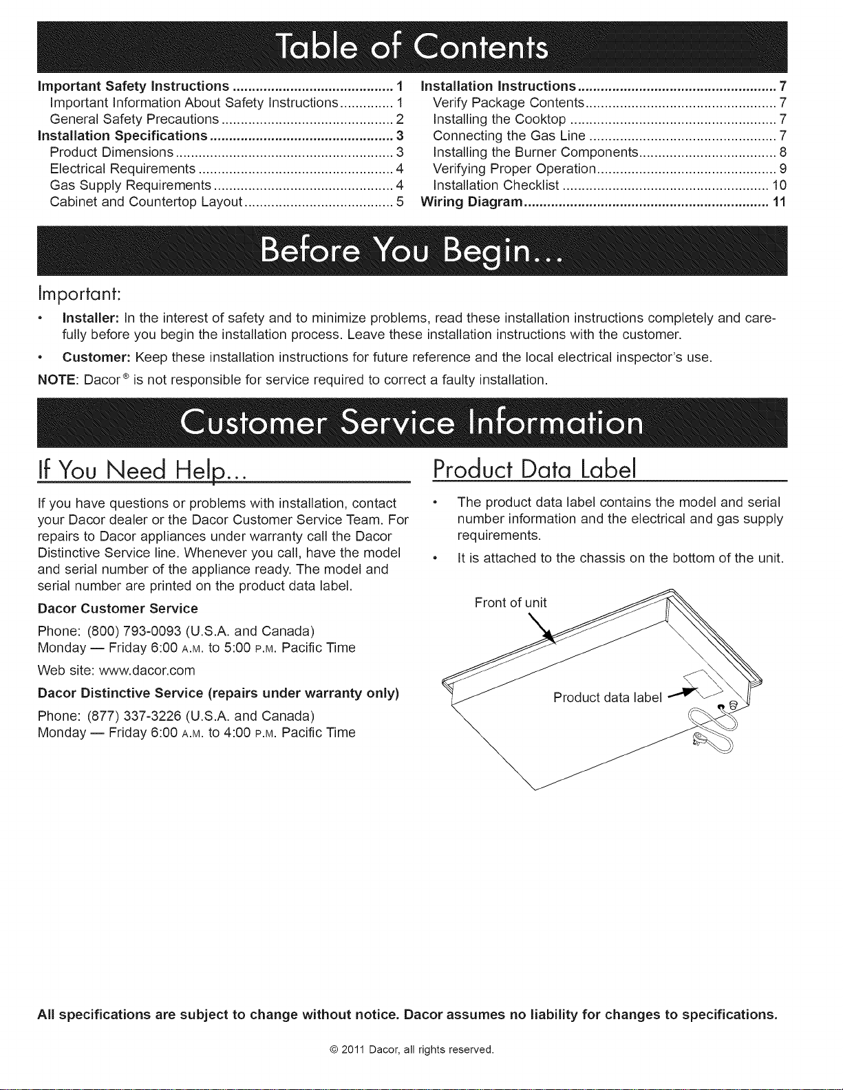
The product data label contains the model and serial
number information and the electrical and gas supply
requirements.
It is attached to the chassis on the bottom of the unit.
Front of unit
All specifications are subject to change without notice. Dacor assumes no liability for changes to specifications.
© 2011 Dacor, all rights reserved.
Page 3

Important Information About
Safety Instructions
The important Safety instructions and warnings in
these instructions are not meant to cover all possible
problems and conditions that can occur. Use common
sense and caution when installing, maintaining or oper-
ating this or any other appliance.
• Always contact the Dacor Customer Service Team
about problems and conditions that you don't under-
stand. See Customer Service information.
Safety Symbols and Labels
[ 1 med,ate haz_t gwANe?uE Rsevere ersonal ]
m ! i iaii
njury or death.
WARNING
HaZards or UnSafe practices that COULD result in SeVere
personal injury or death.
WARNING
TO REDUCE THE RISK OF INJURY TO PERSONS IN
THE EVENT OF A RANGE TOP GREASE FIRE:
a: SMOTHER FLAMES with a close:fitting l!d;cookie
sheet or metal tray, then turnoff the burner: BE
CAREFUL TO PREVENT BURN& If the flames do
not go out immediately, EVACUATE AND CALL THE
b. NEVER PICK UPA FLAMING PAN. youmay
cl DO NOT USE WATER; includ!ng wet dish cloths or
towels- a Violent steam exptosi0n may resu]L
di Use a fire extinguisher ONLY if:
You have a clasS ABC eXtingUisheg and Y0u
already kn0w hoW to 0perate it
0 The fire is small and contained in the area where
it started!
_ The fire department iS being Called
YoU can fight the fire with your back t0 an exit.
WARNING
CAUTION
Hazards or unsafe practices that COULD result in minor
perSonal injury Or property damage:
[ DANGER
IoMPORTANT: !f you smell gas:
Do n0t use 0r l!ght any apPliancel
' Do not touch any electrical Switch or Use any electrical
devices including the telephone in your build ng.
, From aneighbor's phone; mmediately call the gas
Supplier. FOllOWthe gas suppl!er,s instructions:
Y0Ucannot contact the gaS sUpplier. Call the fiie
department:
DANGER
IMPORTANT: DO not stOre OrUse C0mbustible;flammable
oi explosive VaPors and liquids (such as gaS0line)0n 0r
in the vicinitY of this or any 0thor appl!ance! AIs0 keep
!tems that coUld exPlode, Such as aerosol cans, aWay
from the c0okt0p; DO not St0re flammable or exploS!ve
materials in adjacent cabinets or areas (including above
and below the cooktop)i
WARNING ,NEVER use th!s appliance as a space
heater to heat or warm the rooml Doing so may result
in carbon monoxide poisoning and overheating 0fthe
appliance.
WARNING
WARNING _ NEVER
Onthe c00kt0p and c00kt0P Chassis, DOing so blocks
air flow through the c0oktop and may Cause carbon
m0n0X!de poisoningl A!um!num foil linings may als0 trap
heat, caUs!ng a fire hazardl Keep all slots; h01es and
passages clear of grease and grime:
CALIFORNIA PROPOSITION 65 WARNING
The bUrning of gas c0oking fuel generateS some
byZpr0ducts that are on the !ist of substances Which
are kn0wn by the state 0f California t0 Cause Cancer 0r
reproductive barrel California law requires businesses
to warn customers of p0tentia! exposure to such
Substances: To m!nimize exposure t0 these Substancesl
always operate this Unit acc0rding t0 the use and care
manual; enSuring YOu Provide g0Od Ventilati0n when
cooking with gas:
READ AND SAVE THESE INSTRUCTIONS
_a_D_ 1
Page 4
General Safe.'ry_Precautions
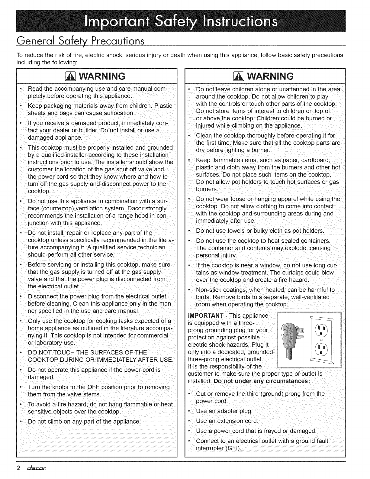
To reduce the risk of fire, electric shock, serious injury or death when using this appliance, follow basic safety precautions,
including the following:
WARNING
- Read the accompanying use and care manual com-
pletely before operating this appliance.
• Keep packagmg materials away from children. Plastic
sheets and bags can cause suffocation.
- If you receive a damaged product, immediately con-
tact your dealer or builder. Do not install or use a
damaged appliance.
This cooktop must be properly installed and grounded
by a qualified installer according to these installation
instructions prior to use. The installer should show the
customer the location of the gas shut off valve and
the power cord so that they know where and how to
turn off the gas supply and disconnect power to the
cooktop.
- Do not use this appliance in combination with a sur-
face (countertop) ventilation system. Dacor strongly
recommends the installation of a range hood in con-
junction with this appliance.
• Do not install, repair or replace any part of the
cooktop unless specifically recommended in the litera-
ture accompanying it. A qualified service technician
should perform all other service.
- Before servicing or installingthis cooktop, make sure
that the gas supply is turned off at the gas supply
talve and that the power plug is disconnected from
he electrical outlet.
Disconnect the power plug from the electrical outlet
before cleaning. Clean this appliance only in the man-
ner specified in the use and care manual.
- Only use the cooktop for cooking tasks expected of a
home appliance as outlined in the literature accompa-
nying it. This cooktop is not intended for commercial
or laboratory use.
- DO NOT TOUCH THE SURFACES OF THE
COOKTOP DURING OR IMMEDIATELY AFTER USE.
- Do not operate this appliance if the power cord is
damaged.
- Turn the knobs to the OFF position prior to removing
them from the valve stems.
| WARNING
Do not leave children alone Or unattended in the area
around the cooktop: Do not allow children to play
Withthe controls or t0uch 0ther parts of the cookt0pl
Do not store items of interest to children on top of
or above the c0okt0p Children could be burned or
injured While climbing On the appliance:
Clean the cooktop thoroughly before operating it for
the first time:Make sure that all the cooktop parts are
dry before lighting a burnerl
, Keep flammable items; such as paper, cardboard;
plastic and cloth awaY from the burners and other hot
surfaces:Do not place such items on the cooktop:
DO not alloW pot holders tO touch hot surfaces orgaS
' De not wear ioose Orhanging apparel while us!ng the
cooktop: Do not allow clothing to come into contact
With the cooktop and surrounding areas dunng and
immediately after Usel
;Do not Use t0wels or bUlky Cl0th as pot h01ders:
, Do not use the cooktop to heat sealed containers:
The container and contents may explode, causing
personal !njUryl
' the Cooktop iS near a w!ndOW, dO nOt use long cur_
tains as window treatment. The curtainS could blow
over the CooktoP and create a fire hazard!
Nomstick coatings; when heated, can be harmful to
birds: Remove birds to a separate; welFventi!ated
room when operating the cooktop:
Prong grounding plug for your :i_i _--
protection against possible _
electric shock hazards: Plug it
only !ntoa dedicated;grounded
three-prong electrical Outlet.
tt is the responsibility of the .........
customer tO make sure the proper type 0f outlet is
installed Donot under any circumstances:
Cut or remove the third (ground) prong from the
- To avoid a fire hazard, do not hang flammable or heat
sensitive objects over the cooktop.
- Do not climb on any part of the appliance.
2 _8C0_
,,, Use an adapter plug
; use an eXtensiOn Cord
i' Usea pOWer cord that is frayed or damagedl
' Connect toan electrical Outlet With a ground fault
interrupter (GFt).
Page 5
[ WARNING !
ObserVe all governing Codes and ordinances during planning and inStallation! contaCt your local building department for I
further informationl
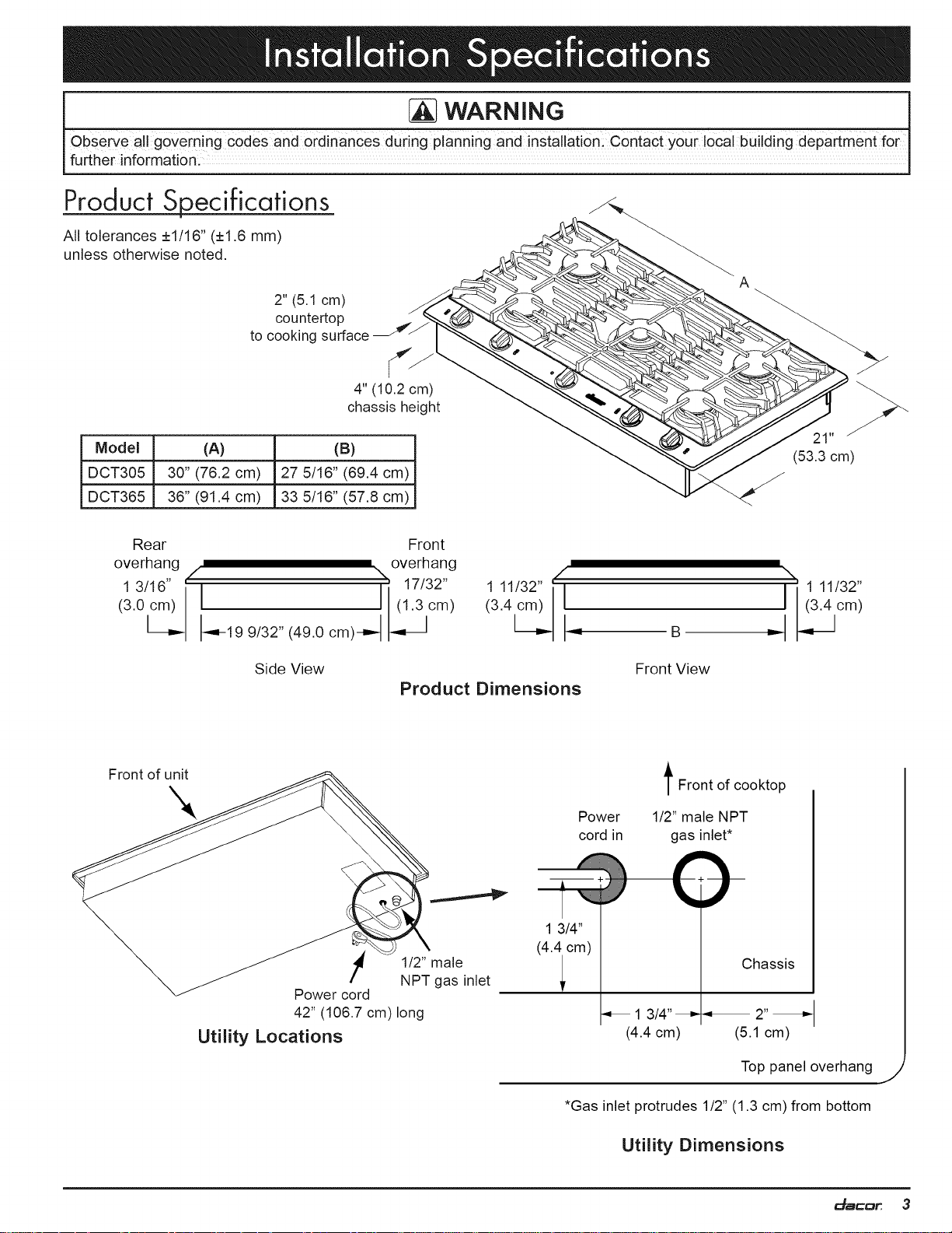
Product Specifications
All tolerances ±1/16" (±1.6 ram)
unless otherwise noted.
A
2" (5.1 cm)
countertop
to cooking surface _/
4" (10.2 cm)
chassis height
Model (A) (B)
DCT305 30" (76.2 cm) 27 5/16" (69.4 cm)
DCT365 36" (91.4 cm) 33 5/16" (57.6 cm)
Rear Front
overhang overhang
13/16" i'/ %: 17/32" 111/32" ]I
Side View
Product Dimensions
Front of unit
Power
cord in
B
Front View
t Front of cooktop
1/2" male NPT
gas inlet*
()--
(53.3 cm)
i i 111/32"
_il_ °m)
Power cord
42" (106.7 cm)long
Utility Locations
1 3/4"
!
1/2" male
NPT gas inlet
(4icm)
_13/4" =< 2"_
(4.4 cm) (5.1 cm)
*Gas inlet protrudes 1/2" (1.3 cm) from bottom
Utility Dimensions
Chassis
Top panel overhang
_a_D_ 3
/
Page 6

Electrical Requirements Gas SuRply Requirements
WARNING
To prevent an electriC shoCk hazardl the p0wer supply
must meet the specificat!ons stated below, Itis the owm
er,s responsibility to make sure that the electrical service
meets electrical [equirements and that the electrical outlet
has been properly installed by a licensed electrician.
The cooktop is supplied with a factory installed, 42
inch long, power cord with a three-prong, grounding
electrical plug. It is connected to the chassis at the bot-
tom right rear corner (see Chassis Bottom Diagram
below). It must be connected to a dedicated, grounded .
three-prong electrical outlet installed by a licensed elec-
trician.
The electrical installation, including minimum supply
wire size and grounding, must be done in accordance
with National Electric Code ANSI/NFPA 70 and local
codes and ordinances. A copy of this standard may be
obtained from:
National Fire Protection Association
1 Batterymarch Park
Quincy, MA 02269-9101
• The correct voltage, frequency and amperage must be
supplied to the electrical outlet according to the product
data label located on the bottom of the chassis. See
the Gas and Electrical Requirements table on this
page for reference.
• Be certain to locate the electrical outlet so that the
power cord may be easily disconnected if the unit
requires service.
Front of unit
Be certain that the cooktop being installed is correct for
the gas service being provided (natural gas or LP gas).
Also, if operating the cooktop at an altitude above 4000
ft. (1219 m) make sure it is equipped for high altitude
operation.
Units equipped for LP operation have "LP" in the
model number listed on the product data label. See the
Chassis Bottom Diagram for label location.
Units equipped for high altitude operation have an "H"
at the end of the model number listed on the product
data label.
Check your local building codes for the proper method
of installation. In the absence of local codes, this
appliance should be installed in accordance with the
National Fuel Gas Code ANSI Z223.1/NFPA 54.
• An external manual shut-off valve must be installed
between the gas inlet and the cooktop for the purpose
of turning on or shutting off gas to the appliance.
The cooktop comes from the factory with a regulator in
the shipping carton. Use only the regulator provided.
The regulator must be installed in the gas line that runs
from the cooktop gas inlet to the gas shut off valve.
• The regulator inlet (female) accommodates a 3/4" gas
line. It can also accommodate a 1/2" gas line using
the included reducer. The inlet to the cooktop itself is
equipped with a 1/2" male NPT fitting.
The cooktop gas connection is located on the bottom of the
cooktop in the back right corner as you face the front of the
unit. See the Chassis Bottom Diagram on this page.
DOT305 NG DOT305 LP
DCT365 NG DCT365 LP
Gas type Natural gas LP gas
Manifold 5" Water 10" Water
pressure column column
Min. gas supply 6" Water 11"Water
pressure * column column
4 _SCD_
Chassis Bottom Diagram
Max. gas supply 1/2 psi 1/2 psi
pressure
Total connected 0.25 Amp. 0.25 Amp.
load (30 Watts) (30 Watts)
Circuit 120 Vac, 120 Vac,
requirement 60 Hz, 15Amp. 60 Hz, 15 Amp.
Gas and Electrical Requirements**
* The gas supply pressure for testing the regulator setting
shall be at least 1 inch water column (249 Pa) above the
specified manifold pressure.
** The electrical and gas data on this page is for reference
only. If the above data does not agree with the product data
label, use the data on the product data label.
Page 7

Cabinet and Countertop Layout
| WARNING
Allow a minimum 1/4" (6 mm) clearance between the
bottom of the cooktop chassis and all combustible sur-
faces, including the upper edge of a drawer installed
below the cooktop.
, Failure to meet or exceed the maximum and minimum
dimensi0nsiclearances stated inthese instructions
may result in afire hazard:
,Follow the countertop manUfactUrerls instruct ons
regarding the minimum c0rner radiUs, use 0f heat
reflective tape; reinforcement of corners; etc:
Carefully check the location where the cooktop will be
installed. For best performance, the cooktop should be
placed away from drafts that may be caused by doors,
windows and heating and air conditioning outlets.
• This appliance is to be used in conjunction with a suit-
able vent hood or approved Dacor raised vent system.
All tolerances +1/16" (+1.6 mm),-0
unless otherwise noted.
1 3"
(33.0 cm)
18" min. 1'3
(45.7 cm)
Combustible
surface to rear
See cutout
dimensions
5/8" min.
(4.1 cm)
See cutout
dimensions
I Distance to combustible surfaces measured from cooking
surface (top of cooktop grate).
2If installing with an overhead range hood, check the hood
specifications for minimum required clearances.
3This specification does not apply for cabinets located
greater than a horizontal distance of 5 1/2" (14.0 cm) from
edge d cooktop. Allow 6 7/8" (17.5 cm) from cutout edge.
Minimum Required Clearances Around the Cooktop
/
"//////// V
1/4" (6 mm)
mimimum clearance
g
to combustible
surfaces
* Allows for clearance between hold down brackets
Model (B) Minimum
DCT305 29 1/4" (74.3 cm)
DCT365 35 1/4" (89.5 cm)
Under Cabinet Clearances
The gas supply piping, gas shut-off valve and the elec-
trical outlet must be located so that they do not inter-
fere with the cooktop when it is installed. If installing
another appliance in the cabinet below, allow for the
routing of gas and electrical service behind it.
The installation must allow for the following:
• Access to the gas shut-off valve and regulator when
the unit is installed.
Access to the electrical outlet when the cooktop is in
place. The 42" (106.7 cm) power cord must be able to
reach the electrical outlet.
Access to the underside of the cooktop for service and
inspection purposes.
Clearance inside the cabinet to allow for proper hold
down bracket installation.
To allow access to the utilities and cooktop bottom, a fixed
shelf should not be installed below the cooktop. See the fol-
lowing pages for countertop cutout dimensions.
Raised Vent CompatibiJity
Model DCT305 is not compatible with a raised vent. If
installing cooktop model DCT365 with a raised vent, install
only Dacor raised vent model ERV3615. Installation of any
other raised vent model may cause improper operation.
Model (A) Minimum (A) Recommended
DCT305 30" (76.2 cm) 36" (91.4 cm)
DCT365 36" (91.4 cm) 42" (106.7 cm)
_a_D_ 5
Page 8

Cutout Dimensions All tolerances +1/16"-0 (+1.6 mm, 0) unless otherwise noted.
Rear
wall
Vertical
combustible
surface
4 1/4" (10.8 cm) min.
from mounting surface to
combustibles below
cooktop chassis
Minimum distance to combustible side
wall above countertop (both sides)
Countertop Cutout Dimensions
Installation Type (C) Minimum (D) (E) (F) Minimum
DCT305* 3 1/4" (8.3 cm) 19 5/8" (49.9 cm) 27 5/8" (85.4 cm) 6 7/8" (17.5 cm)
•DCT365 with no raised vent _ 3 1/4" (8.3 cm) L 19 5/8" (49.9 cm) _ 33 5/8" (85.4 cm) _ 6 7/8" (17.5 cm)
DCT365 with ERV3615 raised vent 3/8" (1.0 cm) 22 3/4" (57.8 cm) 33 5/8" (85.4 cm) 6 7/8" (17.5 cm)
Model DCT305 is not compatible with a raised vent
3/8" min. (1.0 cm)
flat countertop overhang Countertop
., required behind cutout \
Stiffener
DCT365 cooktop
I I ,, Cabinet face '_
Ir-]l.........3/8 min. (1.0 cm) space ,,
/ , • I I
_'11 behind raised vent ,,
II II chassis t° clear stiffener ''I'I'
II IL_ ERV3615 raised vent, ,,
iut • ,,,,
I 1 dimensions/specifications ,,
Check raised vent ,,
I I
I I
I I
IF[ ....to determine proper fit ,,,,
I I
I I
I I
I I
I I
Floor ,,"
iI
6 _SCD_
Side View - DCT365 Cooktop with ERV3615 Raised Vent
Page 9

Verify Package Contents Connecting the Gas Line
• Hold down brackets (2)
• Grates (3)
• Burner sets (5)
• Gas pressure regulator with 3/4" to 1/2" reducer
• Stainless steel cleaner
Installing the Cooktop
WARNING
-Verify that the power supply meets the specifications
• To prevent damage to the gas pressure regu!ator,
install it only after the cooktop is mounted in its perma_
nent position.
CAUTION
-Do not oVer4ighten the hold doWn boltsl OverL
t ghten!ng the hold down bo!ts may result in improper
operation of the dual gaS bUrnersl
; DO not Use a hardening compound or caulk to perma:
nentlY seal the cooktoP into place. The cooktop must
be readily removable if service is requiredl Remova!
sealant tO service the unit will be performed at the
customer,s expense!
,
If the cooktop will be used with a raised vent, install the
vent according to it's installation instructions first.
2. Lower the cooktop into the cutout. Slide it forward as
far as possible and center it side to side.
3. Secure the cooktop to the countertop using the two (2)
provided hold-down brackets as shown.
Hold down _
bracket mounting holes
(both sides)
inlet
t
Power cord
WARNING
- Verify that the gas supply meets specifications before
connection. See page 4.
- Do not install the cooktop without also installing the
included gas regulator. Do not use the cooktop without
the regulator installed.
o Ensure that the arrow on the regulator points in the
direction of the gas flow, towards the cooktop.
- Do not apply excessive pressure when tightenng gas
connections and fittings.
- Do not use Teflon tape, pipe thread sealant or any
other sealing compound on the seat of flared gas line
connections.
• Test the gas lines for leaks as instructed before use.
Do not use a flame to check for leaks.
- The maximum gas supply pressure to the regulator
must never exceed 1/2 psi (3.5 kPa).
- The cooktop and shut-off valve must be disconnected
from the gas supply piping system during any pres-
sure testing exceeding 1/2 psi (3.5 kPa).
• The cooktop must be isolated from the gas supply pip-
ing system by closing the shut-off valve to the cooktop
during any gas supply piping system pressure testing
equal to or less than 1/2 psi (3.5 kPa).
• For LP gas installations, the LP gas tank must have its
own high-pressure regulator in addition to the pressure
regulator supplied with the cooktop.
,
Attach the gas pressure regulator (included with the
cooktop) to the cooktop pipe nipple inlet. For tight
installations, the regulator may be installed upstream
from the pipe nipple, anywhere between the shut-off
valve and the cooktop. For best performance, minimize
gas pressure loss by attaching the regulator as close
as possible to the cooktop gas inlet.
,
Complete connection of the gas supply to the cooktop
by installing a minimum 1/2" flexible gas line (not
included) between the pressure regulator and the shut-
off valve.
,
Check for gas leaks:
¢ Turn all cooktop control valves to the OFF position.
0 Turn on the gas supply valve and check all lines
and connections for leaks using a soap and water
solution or a gas leak detector.
0 Turn the gas supply off.
Hold Down Bracket Installation
_aC'DII, 7
Page 10

Installing the Burner Components
WARNING
, Never attempt to operate the cooktop with any o t e
burner parts removed:
, D0not attempt to adjust the burner air mixture set,
tingS: AHadjustments are preset at the factory
1. Remove the burner rings, burner caps and grates from
their shipping packages.
, Assemble the burners as shown. Match the burner
parts to the correct size and type of burner. When
installing the burner components, make sure they are
centered. Twist each piece back and forth slightly until
it drops completely into place. The burners will not
operate properly unless all of the burner pieces are
properly seated. On model DCT305, the left rear burner
cap has tabs on the bottom that fit into the slots on the
top of the burner ring.
I
Inner burner cap
(bottom shown)
Outer burner ca
Burner ring
Line up
indentations on
bottom of burner
ring with pins on
top of base.
Burner base
SimmerSear TM Burner Assembly
(center of cooktop)
Burner cap
(bottom shown) Fit hole in burner
ring over igniter
/
Igniter
[_ CAUTION:. Top of
igniter is sharp
Burner base
Standard Burner Assembly
Burner cap
(bottom shown)
ring over igniter
Fit hole in burner
Burner rin(@4._
_ Igniter
Burner base igniter is sharp
Left Rear Standard Burner Assembly - DCT305
[_CAUTION: Top of
8 _SCD_
Page 11

IMPORTANT: Install the grates as instructed below for
longest life. When installed properly, the openings in the
grates are centered over the burners.
3. Locate the notch on the bottom of each grate.
,
Use the notch on the bottom of each grate to determine
location and orientation. See diagram below. The notch
on the bottom of each grate goes towards the back of
the cooktop. The notches on the left and right grates go
toward the outside.
5. Gently lower the legs of each grate into the corre-
sponding dimples on the cooktop.
Left grate,
curved fingers
on left
Notch on bottom
toward back
Center grate =
Notch on bottom
toward back
Notch on
bottom toward
back
I
I
I
NOTE: Burner and grate size vary with model
Right grate,
curved fingers on
right
I
I
I
Standard
burner
_a_D_ 9
Page 12

Fiv£ogP Op ,,,.ocoo.,o..oo °o,o.oro,o.ro.or, ,,o,,ow
Ver[ roper er(3tion thesetroubleshootingsteps:
e
WARNING
, Make sure that power to the electrical outlet is turned
Off at the circuit breaker panel Or fuse box and that the
gas is turned offat the gas supply valve before pro-
Ceedingl
' The c0okt0P must be pi0peily gF0Unded at allfimes
when electrical power is applied
Prior to operating the cooktop, read the accompanying use
and care manual carefully.
,
If the control knobs are not already in place, install the
SimmerSear knob (see knob diagrams, bottom right) on
the center valve stem. The remaining knobs install on
the valve stems to the right and left of the center knob.
,
Make sure all the cooktop burner controls are in the
OFF position.
3. Connect the power cord to the electrical outlet.
Verify that power and gas are supplied to the cooktop.
e
Check to make sure that the power plug is connected
to the electrical outlet and that power is turned on at
the circuit breaker panel or fuse box.
Check to make sure that the burner parts are properly
seated.
• If the burner continues to spark after ignition without
stopping, have a licensed electrician check the electri-
cal outlet for proper grounding or reversed polarity.
• Repeat the above burner ignition test.
• If the appliance still does not work, contact Dacor
Distinctive Service at (877) 337-3226. Do not attempt
to repair the appliance yourself. Ifyou need service, be
sure to have the model and serial numbers available
when you call. See inside cover for location.
Dacor is not responsible for the cost of correcting problems
caused by a faulty installation.
4. Turn on power to the electrical outlet at the circuit
breaker panel or fuse box.
, Push down and turn the left front burner control knob
slowl_ counterclockwise to the HIGH posi-
tion. The corresponding burner indicator light
should come on. Verify that the burner igniter
sparks, then return the knob to the OFF
position. Repeat for all of the remaining
control knobs.
,
Turn on the gas supply valve.
7.
Perform the following ignition test for all of the burners,
HIGH
position
one at a time:
HIGH
position
Push down and turn the control knob slowly_coun-
terclockwise to the HIGH position. All of the burner
igniters will spark. It may take up to 4 seconds for
the burner to ignite, at which time the igniters will
stop sparking. If ignition does not occur within 4
seconds, turn the knob to the off position. Wait for at
least 5 minutes to allow any gas to dissipate, then
repeat the test.
Once the burner lights, rotate the control knob coun-
terclockwise from HIGH to LOW to adjust the flame
height progressively. On the SimmerSear burner,
only the center of the burner should be lit when the
knob is in the low position.
When the unit is installed
properly, the flame will be
steady. It will also have a
sharp, blue inner cone pro-
portional to the burner size.
The flame will be reduced
by the Smart Flame TM fea-
ture under the grate fingers
to increase grate life.
Normal Flame
Appearance
10 dacDr
SimmerSear Control Knob (Center)
position
_ HIGH
LOW
position
Standard Burner Control Knob
Page 13

Installation Checklist
| WARNING
To ensure a safe and proper installation, the follow-
ing checklist should be completed by the installer to
ensure that no part of the installation has been over-
looked.
• Proper installation isthe responsibility of the home-
owner. The importance of proper installation of your
Dacor cooktop cannot be overemphasized.
[]
Is the electrical outlet for the cooktop grounded and
located according to these instructions and in accor-
dance with all applicable electrical codes? See page
4.
[]
Is the gas service for the cooktop located and installed
according to these instructions and in accordance with
all applicable codes? See page 4.
[]
Has the gas supply inlet pressure been measured to
ensure that it does not exceed the maximums stated in
these instructions? See page 4.
[]
Is the cooktop secured using the provided hold-down
brackets? See page 7.
[]
Is the cooktop connected to the gas supply according
to these instructions and in accordance with all appli-
cable codes? Did the installer check the gas supply for
leaks? See page 7.
[]
Are the burners and grates properly installed according
to these instructions? See page 8.
[]
Has proper operation been verified?
[]
Has the warranty been activated on-line or the warranty
card filled out completely and mailed?
dacDr_ 11
Page 14

WARNING
Labe! aftw!res pr!ortOdis_c0nnect!0n When se[vicing
controlsl wiring errors can cause improper and J
dangerous operation.
IGNITERS
m
1]
$5
D
$4
FL
[I
D
D
$3
$2
Si
5 PDINT
GAS
RE-IGNITER
120 Vac, 60 Hz.
power supply
m
G
GND
V
N
BK
A
i
]3K
5
]3K
4
i
])K
3
i
BK
2
]3K
i
Verify proper operation
after servicing
I])K
G
±
$5
$4
MC
$3
12 dater
@RL LIGHT
@FL LIGHT
MC LIGHT
FR LIGHT
V@RR LIGHT
Wiring Diagram - DCT305/DCT365
!
0
BK
$2
Page 15

Family Owned
The Life of the Kitchen?
Dacor • 600 Anton Blvd. Suite 1000 Costa Mesa, CA 92626 • Phone: (800) 793-0093 • Fax: (626)403-3130 • www.dacor.com
American Made
 Loading...