

Dacor DARERADWRH105 Installation manual
Installation Instructions
Modernist Range Hood
DHD30M967/DHD36M987/DHD48M987
Part No. 110452 Rev E

Contents
Before You Begin
Important Notes
Customer-Assurance Information
Important Safety Instructions
Related Equipment Safety
Installation Safety
Installation Requirements
Checklist
Preparing to Install the Hood
Installation Planning
Hood Specifications
Electrical/Ductwork Connections
Overall Hood Dimensions
Cabinet Layout Dimensions
Installation Instructions
Meeting Electrical Codes
Preparation and Setup
Installing the Electrical Source
Meeting Installation Requirements
Planning th
Planning the Mounting Location
Marking the Exhaust-Duct Centerlines
Installing the Support Brackets
Rotating the Blowers for Rear Exhaust
Assembling the Filters
Using the Optional Dual-to-Single Transition Kit #AHT10
Hanging the Hood
Hardwiring the Hood
Inserting Light Bulbs
Verifying Proper Function
Wiring Diagram
e Ductwork
3
3
3
4
4
4
6
6
6
7
8
9
10
11
12
12
12
13
13
14
16
17
18
19
22
22
23
24
26
26
27
2 English
Before You Begin
Important Notes
Installer
• In the interest of safety and to minimize
problems, read this manual thoroughly before
starting the installation.
• Leave this manual with the customer.
• Show the owner how to shut off power to the
hood.
Customer
Keep this manual for personal and professional
reference.
Customer-Assurance Information
To resolve questions and installation issues, contact your Dacor® dealer or Dacor Customer
Assurance. Before calling, have the hood’s model and serial numbers available. (See the data label
inside the hood above the filters on the chassis' rear wall).
Phone: (800) 793-0093 x2813 (US, Canada)
Hours of Operation: Mon – Fri 5:00 a.m. to 5:00 p.m. Pacific Time
Website: www.dacor.com/customer-care/contact-us
All specifications are subject to change without notice. Dacor assumes no liability for such changes.
© 2017 Dacor, all rights reserved.
English 3

Important Safety Instructions
Related Equipment Safety
Remove and dispose of all packaging before using the hood. Do not let children play with the
packaging.
Never modify the construction of the hood (e.g., do not remove panels, wire covers, or screws).
DANGER
ELECTRICAL SHOCK HAZARD
To avoid risk of electrical shock, personal injury, or death; ensure the hood is properly grounded
according to local codes or in their absence, with the National Electrical Code (NEC). ANSI/NFPA 70latest edition.
WARNING
MOVING HAZARD
To avoid personal injury, use at least two people to handle the hood. Use an appliance dolly if
possible.
Installation Safety
The Important Safety Instructions and warnings in this manual cannot cover all possible issues.
Use common sense and caution when installing, maintaining, and operating the hood.
Contact Dacor Customer Assurance (Pg. 3) about issues and conditions you do not understand.
WARNING
To reduce risk of property damage, fire, personal injury, and death:
• Do not store or use combustible material (e.g., gas, alcohol, paint thinner, aerosol cans) on
nearby countertops or in adjacent cabinetry.
• Follow the directions in this manual exactly
• Use the hood only as intended by the manufacturer. If you have questions, contact Dacor (Pg. 3).
• Installation and wiring must be done by qualified person(s) according to applicable codes and
standards, including fire-rated construction.
• Sufficient air is needed for proper expulsion of cooktop gases to prevent backdraft; follow the
cooktop manufacturer’s guidelines and safety standards such as those published by the National
Fire Protection Assn (NFPA), and the American Society for Heating, Refrigeration and Air
Conditioning Engineers (ASHRAE), and the local code authorities.
• When cutting or drilling into a wall or ceiling, take care not to damage wiring and other utilities.
• Ducted fans must always be vented to the outdoors.
• Do not use the hood to vent hazardous/explosive materials or vapors. If you have questions,
contact Dacor (Pg. 3).
4 English

Important Safety Instructions
Installation Safety, cont.
WARNING
To reduce risk of property damage, fire, personal injury, and death:
• If you receive a damaged product, immediately contact the dealer/builder. Do not install/use a
damaged hood.
•
Install the hood as instructed in this manual and as specified by the cooktop/range manufacturer.
Improper installation, adjustment, alteration can cause serious personal injury or property
damage.
• Do not install/repair/replace any part of the range hood unless specifically instructed in this
manual. A qualified service technician should perform all other service.
• Do not use an extension cord or adapter plug with the hood.
• Do not tamper with the controls.
• Never let the filters become blocked/clogged, or foreign objects (e.g., cigarettes, napkins) be
sucked into the hood.
• Do not use window coverings that could blow over the cooking surface and hood.
• Use only metal ducting.
• The minimum vertical distance between the cooking surface and the lowest part of the hood
must be 30” (76.2 cm). See the instructions in this manual for this distance in your specific case.
• Do not try to operate the hood during a power outage.
• Always turn the hood ON if cooking at high heat or when flaming food.
• Clean ventilating fans frequently so grease does not collect on the filter or other hood parts.
English 5

Installation Requirements
Installation Checklist
The installer should review this checklist to verify the thoroughness/accuracy of the installation.
The owner is ultimately responsible for the unit's proper installation.
WARNING
The hood is properly attached to the wall as instructed (Pg. XX).
Ducting is fully installed; joints are secured with sheet-metal screws and wrapped with foil tape
(Pg. 21-23).
The hood is wired/grounded as instructed and per all applicable electric codes (Pgs. 18-19).
Filters are assembled as instructed (Pg. 30).
The setup was verified.
Any problems were noted on the warranty card or during the online warranty activation.
The warranty card was
Preparing to Install the Hood
completed and mailed, or the warranty was activated online.
Have these tools and hardware available before starting the installation.
Hood Installation
• Phillips screwdriver
• Flat-head screwdriver
• Pencil/marking tool
• Wire connector caps
• Wire stripper
• Drill, bits
• Level
• Junction box
• Jigsaw
• 8" ducting
• Foil tape
• Sheet-metal screws
Dual-to-Single Vent Transition Kit (option)
• Dacor Kit #AHT10 (DHD48 only)
• 10" ducts, ducting material
• Drill, bits
• Sheet-metal screws
• Foil tape
Blower Rotation (option)
• Phillips screwdriver
• 5/16" nutdriver
6 English

Installation Requirements
Preparing to Install the Hood, cont.
Parts List
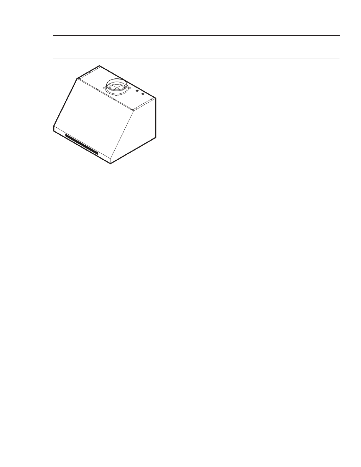
Hood (1)
(models vary in size)
Holding brackets, Hardware (2) Dimmable LED light bulbs
Product literature** (2) Dacor cleaning cream (1)
Grease channel (1)
48” (4), 36” (3), 30” (2)
Stainless-steel units only
Baffle-style filter* 48” (4),
36” (3), 30” (2)
Light-replacement tool (1)
* Ready-to-assemble kit
** Installation Instructions, User Manual
Installation Planning
• The owner shall ensure that the hood is installed by qualified personnel.
• The hood should be placed for convenient access. Ensure that electrical power can be provided
to the selected location and that the outlet is easily accessible for service/emergency shutoff
• All minimum clearances must be met. Dimensions shown provide minimum clearances unless
otherwise noted.
• The specified minimum cabinet depth and width must be provided.
• Ensure that you have all tools/materials needed for proper installation before starting.
.
English 7
Installation Requirements
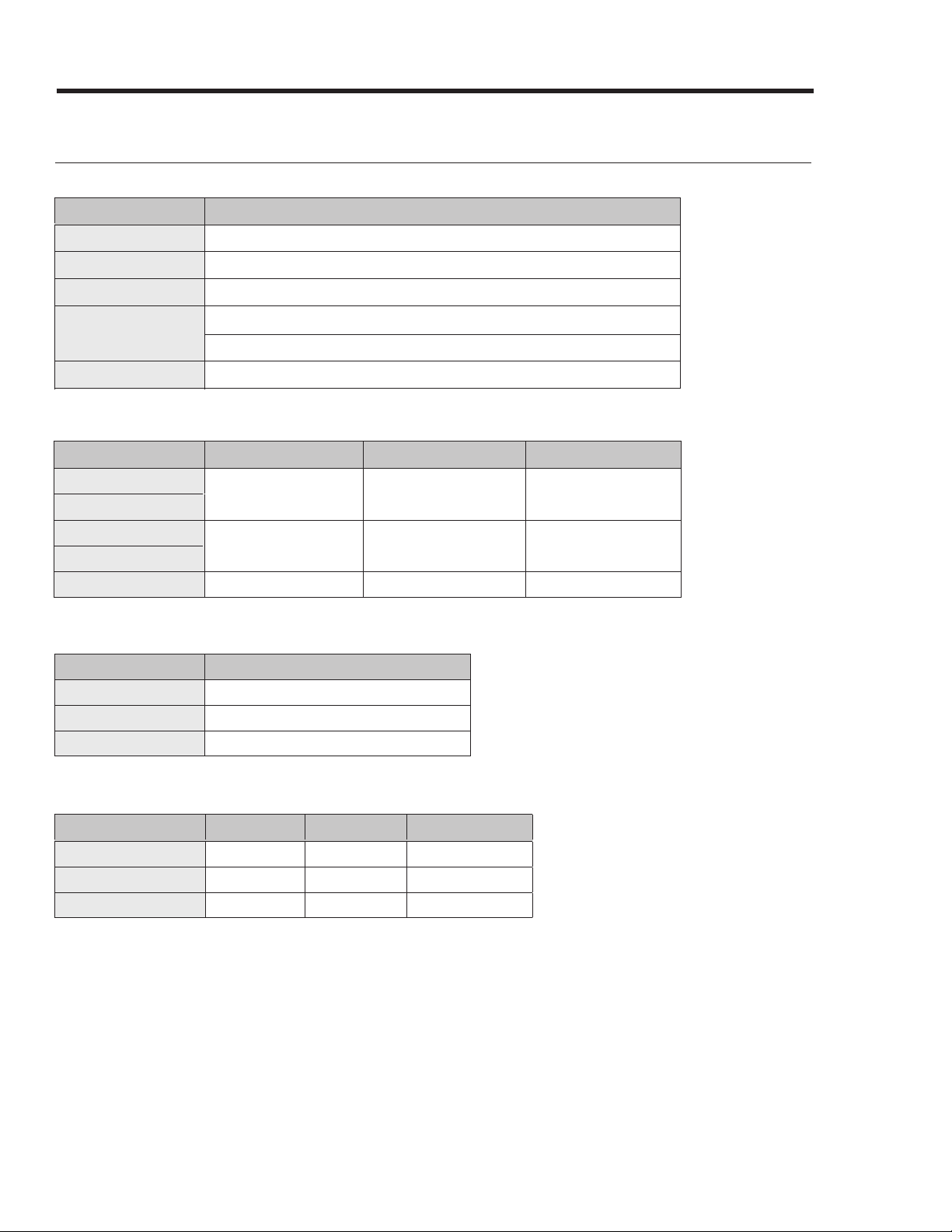
Hood Specifications
General: All Models (DHD30/36/48)
Features Description
Blower Speeds
Filters
Exhaust(s)
Total Connect Load
Lights
Four (4)
Baffle style, dishwasher safe
8” duct diameter
30”, 36”: 120V, 60 Hz, 15 Amp (actual load 3.3 Amp, 6 Amp initial surge)
48”: 120V, 60 Hz, 15 Amp (actual load 6.1 Amp, 12 Amp initial surge)
Dimmable LED: PAR16 E26/27; 120V, 7.5W (75W Max. other bulbs)
General: Individual Models (DHD30/36/48)
Components
Lights
Filters
Blowers
Exhaust Vents
Blower Rating
48” 36” 30”
4 3 2
2 1 1
1200 CFM 600 CFM 600 CFM
Weight: Individual Models (DHD30/36/48)
Model Weight
30
36
48
53 lbs (24 kg)
57 lbs (26 kg)
77 lbs (35 kg)
External Features: Individual Models (DHD30/36/48)
Model Top Vent Rear Vent
30
36
48
x x x
x x x
x x x
Rotatable Fan
8 English
Installation Requirements
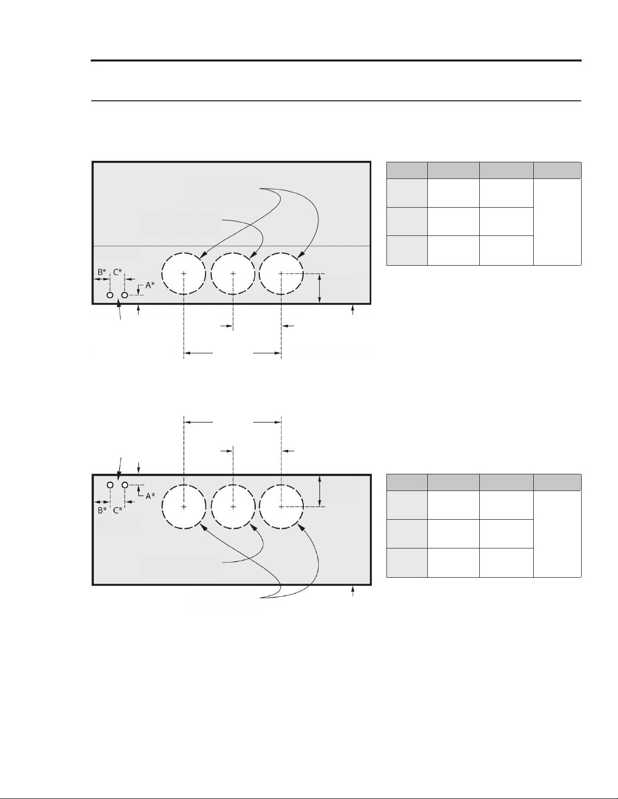
Electrical/Ductwork Connections
Connect wires and ductwork through the top or rear of the hood. Before installing the hood, mark
the access holes according to the diagrams below. (Tolerances: +1/16” -0”, unless otherwise stated.)
Top Connections: All models
Dual-Exhaust
Standard 8" duct
Single-Exhaust
Standard 8" duct
*
See table
7/8 in. (5.1 cm) dia.
Electrical-access
holes (2)
Hood
C/L
19 3/4 in.
(50.2 cm)
Rear Connections: All models
19 3/4 in.
7/8 in. (5.1 cm) dia.
Electrical-access
holes (2)
(50.2 cm)
Hood
C/L
9 7/8 in.
(25.1 cm)
9 7/8 in.
(25.1 cm)
5 3/4 in.
(14.6 cm)
Hood back
(against wall)
Model
48
36
30
A
B C
1 1/2”
(3.81 cm)5”(12.7 cm)
1 1/2”
(3.81 cm)
1 1/2”
(3.81 cm)
4 1/2”
(11.43 cm)
5 1/2”
(14. cm)
3”
(7.62 cm)
*
See table
Single-Exhaust
Standard 8" duct
Dual-Exhaust
Dual-Exhaust
Standard 8" duct
Standard 8" duct
5 3/4 in.
(14.6 cm)
Hood bottom
Model
48
36
30
A
B C
1”
(2.54 cm)5”(12.7 cm)
1”
(2.54 cm)
1”
(2.54 cm)
4 1/2”
(11.43 cm)
5 1/2”
(14. cm)
3”
(7.62 cm)
English 9
 Loading...