

Page 1

567
Operating Manual
Page 2

All rights reserved.
Property of Dürkopp Adler AG and protected by copyright. Any reuse
of these contents, including extracts, is prohibited without the written
approval in advance of Dürkopp Adler AG.
Copyright © Dürkopp Adler AG – 2015
Page 3

Table of Contents
1 About this manual..................................................................................3
1.1 Scope of application of the manual.......................................................3
1.2 Applicable documentation.....................................................................3
1.3 Damage during transport.......................................................................3
1.4 Limitation of liability...............................................................................3
1.5 Used symbols........................................ .. ..............................................4
2 Safety instructions............................................................... ..................5
2.1 General safety instructions....................................................................5
2.2 Signal words and symbols used in safety instructions ..........................7
3 Performance description ................................................................... ....9
3.1 Features................................................................................................9
3.2 Declaration of conformity.......................................................................9
3.3 Intended use..........................................................................................9
3.4 Technical data.....................................................................................10
3.5 Additional equipment...........................................................................11
4 Device description...............................................................................13
5 Operating instructions .........................................................................15
5.1 Switching the power supply on and off................................................15
5.2 Inserting and replacing the needle......................................................16
5.3 Threading in the needle thread ................................... ........................18
5.4 Inserting and winding on the hook thread ...........................................21
5.5 Replacing the hook thread bobbin.......................................................23
5.6 Thread tension ............................................................... .....................24
5.6.1 Adjusting the needle thread tension....................................................25
5.6.2 Adjusting the hook thread tension.......................................................27
5.7 Setting the thread regulator.................................................................27
5.8 Ventilating the sewing feet ..................................................................29
5.9 To hold the sewing feet in the upper position......................................30
5.10 Setting the sewing foot pressure.........................................................31
5.11 Setting the sewing foot stroke.............................................................32
5.12 Adjusting the stitch length ...................................................................34
5.13 Keypad on the machine arm ...............................................................35
5.14 Operating the control system ..............................................................36
5.15 Sewing.................................................................................................37
6 Maintenance........................................................................................39
6.1 Cleaning work......................................................................................39
6.1.1 Cleaning the machine..........................................................................39
6.1.2 Cleaning the motor fan sieve...............................................................41
6.2 Checking the oil level ..........................................................................42
6.2.1 Lubrication of the upper part of the machine.......................................42
6.2.2 Hook lubrication................................................................................. ..43
6.3 Checking the pneumatic system .........................................................44
6.4 Repairs................................................................................................46
Operating manual 567 Version 01.0 - 01/2015 1
Page 4

Table of Contents
7 Set-up instructions............................................................................... 47
7.1 Checking the delivery scope ............................................................... 47
7.2 Removing the transport securing devices ...........................................48
7.3 Fitting the frame components..............................................................49
7.4 Completing the table plate................................................... ... ... ..........50
7.5 Fastening the table plate to the frame.................................................51
7.6 Setting the working height...................................................................52
7.7 Control.................................................................................................53
7.7.1 Fitting the control.................................................................................53
7.7.2 Fitting the pedal and setpoint device...................................................54
7.8 Inserting the machine upper section ...................................................55
7.9 Fitting the oil extraction line.................................................................56
7.10 Fitting the control panel.......................................................................57
7.11 Electrical connection ...........................................................................58
7.11.1 Checking the mains voltage................................................................58
7.11.2 Connecting the control ........................................................................58
7.11.3 Connecting the sewing machine upper section...................................59
7.11.4 Establishing equipotential bonding......................................................60
7.11.5 Fitting and connecting the knee switch ...............................................61
7.12 Pneumatic connection.........................................................................62
7.12.1 Fitting the maintenance unit................................................................62
7.12.2 Setting the operating pressure............................................................63
7.13 Lubrication...........................................................................................64
7.13.1 Lubrication of the upper part of the machine.......................................64
7.13.2 Hook lubrication................................................ ... ................................66
7.14 Sewing test..........................................................................................67
8 Disposal...............................................................................................69
9 Appendix .............................................................................................71
2
Operating manual 567 Version 01.0 - 01/2015
Page 5

About this manual
1 About this manual
1.1 Scope of application of the manual
This manual describes the intended use and the set-up of the special
sewing machine 567.
It applies to all submodels listed in Section 3 Performance descrip-
tion.
1.2 Applicable documentation
The device contains built-in components of other manufacturers,
e.g. drive motors. The corresponding manufacturers have performed
a hazard assessment for these purchased parts and confirmed compliance of the design with the European and national specifications.
The intended use of the built-in components is described in the
corresponding manuals of the manufacturers.
1.3 Damage during transport
Dürkopp Adler cannot be held liable for any damage during transport.
Check the delivered product immediately after receiving it. Report any
damage to the last transport manager. This also applies if the packaging is not damaged.
Keep the machines, devices and packaging material in the condition
they were at the time when the damage was identified. That secures
any claims towards the transport company.
Report all other complaints to Dürkopp Adler immediately after receiving the product.
1.4 Limitation of liability
All information and notes in this operating manual have been compiled
in accordance with the latest technology and the applicable standards
and regulations.
The manufacturer cannot be held liable for any damage due to:
• Failure to observe the manuals
• Improper use
• Unauthorized modifications to the machine
• The deployment of untrained personnel
• Damage during transport
• Using spare parts not approved
Operating manual 567 Version 01.0 - 01/2015 3
Page 6

About this manual
1.
2.
...
1.5 Used symbols
Correct setting
Indicates how the correct setting should look.
Faults
Indicates faults which could occur in the event of an incorrect setting.
Steps of action for operation (sewing and setting up)
Steps of action for service, maintenance, and assembly
Steps of action using the control panel for the software
The individual steps of action are numbered:
1. First step of action
2. Second step of action
It is vital that you adhere to the step sequence.
Result of an action
Change to the machine or in the display.
Important
Here, you must take special care when performing a step of action.
Information
Additional information, e. g. about alternative operating options.
Sequence
Indicates which work you have to perform before or after a setting.
References
A reference to another text passage follows.
4
Operating manual 567 Version 01.0 - 01/2015
Page 7

Safety instructions
2 Safety instructions
This section contains basic instructions for your safety. Read the
instructions carefully before setting up, programming, servicing, or
operating the machine. Make sure to follow the information included
in the safety instructions. Failure to do this can result in serious injury
and damage to the machine.
2.1 General safety instructions
Only authorized persons may use the machine. Every person who
works with the machine must have read the operating manual first.
The machine may only be used as described in this manual.
The operating manual must be available at the machine's location at
all times.
Also observe the safety instructions and the operating manual of the
drive motor's manufacturer.
Observe the generally applicable safety and accident prevention regulations and the legal regulations concerning industrial safety and the
protection of the environment.
All warnings on the machine must always be in legible condition and
may not be removed. Missing or damaged labels must be replaced
immediately.
For the following work, the machine must be disconnected from the
power supply using the main switch or by disconnecting the power
plug:
• Threading
• Replacing the needle or other sewing tools
• Leaving the workplace
• Performing maintenance work and repairs
Operating manual 567 Version 01.0 - 01/2015 5
Page 8

Safety instructions
Inspect the machine while in use for any externally visible damage.
Interrupt your work if you notice any changes to the machine. Report
any changes to your supervisor. A damaged machine may not be
used any more.
Machines or machine parts that have reached the end of their service
life may not be used any more. They have to be disposed of correctly
and in accordance with the applicable statutory provisions.
The machine may only be set up by qualified specialists.
Maintenance work and repairs may only be carried out by qualified
specialists.
Safety equipment may not be removed or put out of service. If this
cannot be avoided for a repair operation, the safety equipment must
be refitted and put back into service immediately afterwards.
Work on electrical equipment may only be carried out by qualified
electricians.
The connecting cable must have a power plug approved in the specific
country. The power plug may only be connected to the power cable
by a qualified electrician.
Work on live components and equipment is prohibited. Exceptions
are defined in the standard DIN VDE 0105.
Missing or faulty spare parts could impair safety and damage the
machine. Therefore only use original spare parts from the manufacturer.
6
Operating manual 567 Version 01.0 - 01/2015
Page 9

Safety instructions
General danger
Danger due to sharp objects
Danger due to electric shock
Danger due to crushing
2.2 Signal words and symbols used in safety
Color bars enclose the safety instructions in the text.
Signal words specify the severity of a danger:
• Danger: Resulting in death or serious injury.
• Warning: Death or serious injury possible.
• Caution: Moderate to minor injuries possible.
• Attention: Damage possible.
In the case of dangers to personnel, the following symbols indicate
the type of hazard:
instructions
Operating manual 567 Version 01.0 - 01/2015 7
Page 10

Safety instructions
Type and source of the danger
Consequences in the event of noncompliance
Measures for avoiding the danger
This is what a hazard warning looks like for a hazard
that will result in serious injury or even death if not
DANGER
Type and source of the danger
Consequences in the event of noncompliance
Measures for avoiding the danger
This is what a hazard warning looks like for a hazard
that could result in serious injury or even death if not
complied with.
WARNING
Type and source of the danger
Consequences in the event of noncompliance
Measures for avoiding the danger
This is what a hazard warning looks like for a hazard
that could result in moderate or minor injury if not
complied with.
CAUTION
Type and source of the danger
Consequences in the event of noncompliance
Measures for avoiding the danger
This is what a hazard warning looks like for a hazard that could
result in material damage if not complied with.
ATTENTION
Examples of the layout of the safety instructions in the text:
8
Operating manual 567 Version 01.0 - 01/2015
Page 11

Performance description
3 Performance description
3.1 Features
The Dürkopp Adler 567 is a flatbed sewing machine for a double
lockstitch.
General technical features
• Oversize vertical hook (XXL)
• Feed: Lower feed, needle feed, and alternating foot-upper feed
• Maximum passage with ve ntilated sewing fe et: 20 mm (DC drive
with reversing mechanism required in order to position the needle above the feet)
• Electromagnetically actuated thread cutter with 15 mm residual
thread length
• Safety snap-on coupling which prevents any misadjustment or
damage to the hook in the event of a thread jamming
• Automatic wick lubrication for machine and hook with oil level
indicator at the column
• Integrated winder
3.2 Declaration of conformity
The machine complies with the European regulations specified in the
declaration of conformity or in the installation declaration.
3.3 Intended use
The Dürkopp Adler 567 is for sewing light to moderately heavy material.
The following needle strengths must be used depending on the material to be sewn:
• Light to moderately heavy material: 90 – 110 Nm
• Moderately heavy material: 110 – 140 Nm
• Heavy material: 140 – 180 Nm
The machine is only intended for processing dry material.
The material to be sewn must contain no hard objects.
The sewing machine is intended for industrial use.
The manufacturer will not be held liable for damage resulting from
improper use.
Operating manual 567 Version 01.0 - 01/2015 9
Page 12

Performance description
3.4 Technical data
Noise levels
Workplace-specific emission value as per DIN EN ISO 10821:
567-180142: LC = 78 dB (A) ± 1.07 dB (A)
For: Stitch length: 7.2 mm.
Sewing foot stroke: 1.5 mm.
Number of stitches: 1900 rpm
Material to be sewn: 4x material G1 DIN 23328
Features
Sewing stitch type Double lockstitch 301
Hook type Vertical hook, oversized (XXL)
Number of needles 1
Needle system 134-35
Maximum needle strength [Nm] 180
Maximum sewing thread thickness 80/3 –10/3
Stitch length, forwards / backwards
[mm]
Adjustable stitch lengths 1
Maximum number of stitches [rpm] 3000
Number of stitches on delivery [rpm] 3000
Reduction of the number of stitches
with stroke exceeding 3 mm
Reduction of the number of stitches
with stroke exceeding 5 mm
Reduction of the number of stitches
with stroke exceeding 6.5 mm
Maximum fan height
(*only with reversing mechanism)
Maximum sewing foot stroke 9
Positive operating pressure [bar] 6
Air consumption [NL] 0.7
Length/width/height [mm] 690/220/460
Weight/with direct drive [kg] 55/59
Rated voltage [V/Hz] Depends on the drive package
Rated voltage on delivery [V/Hz] Depends on the drive package
Rated power [kVA] Depends on the drive package
Submodels:
567-180142
9 / 9
2400
2000
1800
20*
10
Operating manual 567 Version 01.0 - 01/2015
Page 13

Performance description
3.5 Additional equipment
Additional equipment Material number
NK 20-1 electropneumatic needle cooling from above 0867 590014 x
NK 20-2 electropneumatic needle cooling from below 0867 590024 x
RFW 20-3 residual-thread monitor for the hook thread,
XXL hook, 1-needle machines
WE-8 maintenance unit for additional pneumatic
equipment
Halogen sewing lamp for upper sewing machine
section
Sewing lamp attachment set 0907 487519 X
Sewing lamp transformer for halogen sewing lamp 0798 500088 X
1-diode sewing lamp with attachments 9880 867103 X
Power supply unit k for integrated sewing lamp
and 1-diode sewing lamp
Pneumatic connection package for connecting frames
with maintenance unit
Edge stop N800 040367 X
Kit for pneumatic rapid stroke adjustment and 2nd
thread tensioner
0867 590114 x
9780 000108 X
9822 510003 X
9850 001089 X
0797 003031 X
0767 590500 X
Submodels:
567-180142
Knee switch for pneumatic rapid stroke adjustment 9880 002005 x
Cable, RS232 DB9ST-DB9BU (extension for setpoint
device on height-adjustable frames)
Frames
MG 55-3 frame set for motor attached to the upper
section, table plate 1060 x 580 m with pedal
= standard equipment
X = optional additional equipment
Operating manual 567 Version 01.0 - 01/2015 11
9835 200233 x
MG55 400424 X
Page 14

Performance description
12
Operating manual 567 Version 01.0 - 01/2015
Page 15
Device description
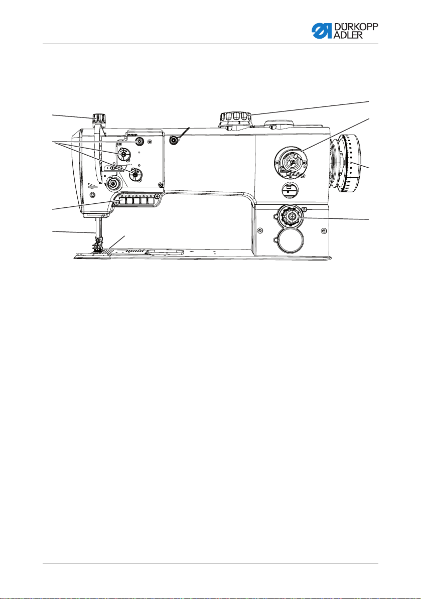
4 Device description
Fig. 1: Complete overview
1
2
3
4
(1) - Adjusting wheel for the sewing foot pressure
(2) - Thread tensioners
(3) - Keypad on the machine arm
(4) - Needle bar
(5) - Hook (under the needle plate)
(6) - Adjusting wheel for the stitch length
(7) - Handwheel
(8) - Winder for the hook thread
(9) - Adjusting wheel for the sewing foot stroke
5
9
8
7
6
Operating manual 567 Version 01.0 - 01/2015 13
Page 16

Device description
14
Operating manual 567 Version 01.0 - 01/2015
Page 17

Operating instructions
+/–+/–
3
2
1
(1) - Indicator lamp on the keypad (2) - Indicator lamp on the control
(3) - Main switch for power supply
5 Operating instructions
5.1 Switching the power supply on and off
The lower main switch (2) on the control regulates the power supply.
Fig. 2: Switching the power supply on and off
To switch on the power:
1. Press the main switch (3) down to the "I" position.
The indicator lamps (1) and (2) light up.
To switch off the power:
1. Press the main switch (3) up to the "0" position.
The indicator lamps (1) and (2) go out.
Operating manual 567 Version 01.0 - 01/2015 15
Page 18

Operating instructions
Risk of injury by the needle point and moving
parts.
Switch off the sewing machine before replacing the
needle.
Do not touch the needle point.
WARNING
Damage to the machine, needle breakage, or thread damage possible due to incorrect di stance between the needle
and hook point.
After inserting a needle with a new size, check the distance to
the hook point. Reset the distance if necessary.
ATTENTION
5.2 Inserting and replacing the needle
Sequence
After changing to another needle strength, adjust the distance
between the hook and needle ( Service instructions, sect. 11.1
Adjusting the lateral hook distance).
Faults when the hook distance is incorrect
After inserting a thinner needle:
• Faulty stitches
• Damage to thread
After inserting a thicker needle:
• Damage to the hook point
• Damage to the needle
16
Operating manual 567 Version 01.0 - 01/2015
Page 19

Operating instructions
1
2
3
4
(1) - Needle bar
(2) - Fastening screw
(3) - Groove
(4) - Hook
Fig. 3: Inserting and replacing the needle
1. Turn the handwheel until the needle bar (1) reaches the upper
2. Loosen the fastening screw (2).
3. Pull the needle out towards the bottom.
4. Insert the new needle.
5. Important: Align the needle in such a way that the groove (3)
6. Tighten the fastening screw (2).
end position.
faces the hook (4).
Operating manual 567 Version 01.0 - 01/2015 17
Page 20

Operating instructions
Risk of injury by the needle point and moving
parts.
Switch off the sewing machine before inserting the
thread.
WARNING
1
2
(1) - Guide on the unwinding bracket
(2) - Thread reel holder
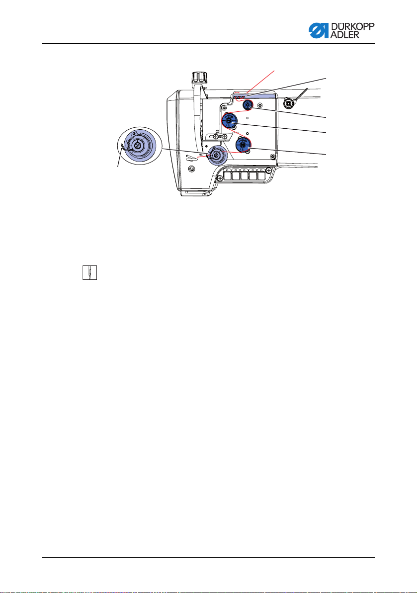
5.3 Threading in the needle thread
Fig. 4: Thread guide on the unwinding bracket and machine arm
1. Fit the thread reel on the thread reel holder.
2. Insert the thread from the rear to the front through a hole in the
guide on the unwinding bracket.
Important: The unwindi ng bracket must be paral lel to the thread
reel holder.
18
Operating manual 567 Version 01.0 - 01/2015
Page 21
Operating instructions
5
4
3
2
1
(1) - Thread tensioning spring
(2) - Main tensioner
(3) - Additional tensioner
(4) - Pre-tensioner
(5) - Thread guide
Fig. 5: Threading procedure for needle thread – part 1
3. Insert the thread in a wavelike manner through the three holes of
4. Guide the thread clockwise around the pre-tensioner (4).
5. Guide the thread counterclockwise around the additional
6. Guide the thread clockwise around the main tensioner (2).
7. Pull the thread under the thread tensioning spring (1).
the thread guide (5): From top to bottom through the right hole,
then from bottom to top through the hole in the middle, and finally
from top to bottom through the left hole.
tensioner (3).
Operating manual 567 Version 01.0 - 01/2015 19
Page 22
Operating instructions
<
^
0
6
7
8
9
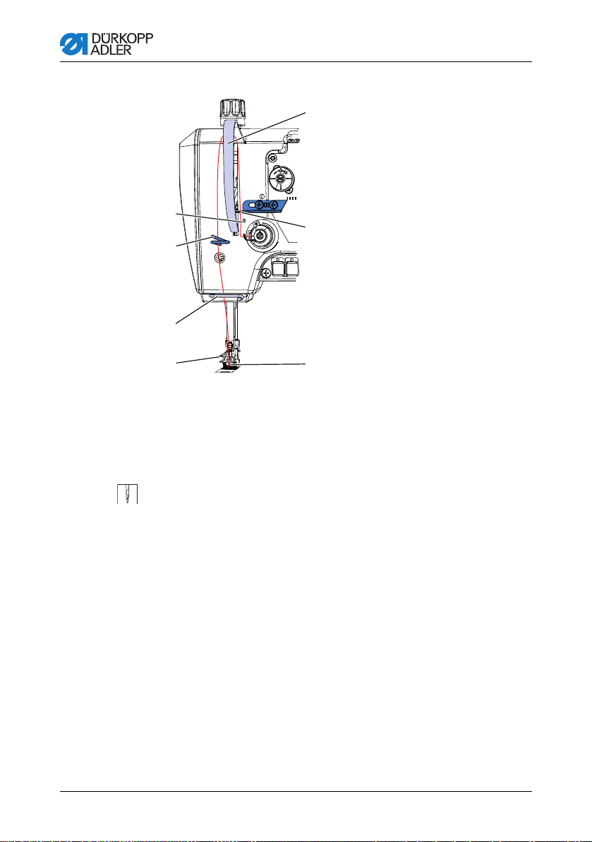
(6) - Thread guide
(7) - Thread guide
(8) - Lower thread guide
(9) - Thread guide on the
needle bar
(10) - Needle eye
(11) - Thread regulator
(12) - Thread lever protection
Fig. 6: Threading procedure for needle thread – part 2
20
8. Guide the thread under the thread guide (6).
9. Insert the thread from bottom to top through the hole on the thread
regulator (11).
10.Insert the thread from the right to the left through the thread lever
behind the thread lever protection (12).
1 1.Insert the thread through the thread guide (7).
12.Insert the thread through the lower thread guide (8).
13.Insert the thread through the thread guide on the needle bar (9).
14.Insert the thread through the needle eye (10) in such a way that
the loose thread end faces the hook.
Operating manual 567 Version 01.0 - 01/2015
Page 23

Operating instructions
Risk of injury by the needle point and moving
parts.
Switch off the sewing machine before inserting the
thread.
WARNING
(1) - Thread guide
(2) - Pre-tensioner
(3) - Winder
5.4 Inserting and winding on the hook thread
Fig. 7: Winding on the hook thread – part 1
1
2
3
Operating manual 567 Version 01.0 - 01/2015 21
1. Fit the thread reel on the thread reel holder.
2. Insert the thread from the rear to the front through a hole in the
guide on the unwinding bracket.
Important: The unwindi ng bracket must be paral lel to the thread
reel holder.
3. Insert the thread in a wavelike manner through the three holes of
the thread guide (1): From top to bottom through the uppermost
hole, from bottom to top through the hole in the middle, and finally
from top to bottom through the lowest hole.
4. Guide the thread counterclockwise around the pre-tensioner (2).
5. Guide the thread to the winder (3).
Page 24

Operating instructions
(1) - Bobbin lever
(2) - Bobbin shaft
(3) - Cutter
Damage to the sewing feet or needle plate possible if the
thread is wound on without material.
Lock the sewing feet in place in the highest position and adjust
the sewing foot stroke to the smallest value if you wind on the
hook thread without sewing the material.
ATTENTION
Fig. 8: Winding on the hook thread – part 2
3
2
1
6. Clamp the thread behind the cutter (3) and tear off the loose end
behind it.
7. Fit the bobbin on the bobbin shaft (2).
8. Turn the bobbin clockwise until it clicks.
9. Pull the bobbin lever (1) up.
The hook thread is normally wound on when sewing is in progress.
However, you can also wind on the hook thread without having to
sew, e.g. if you require a full bobbin in order to start sewing.
Winding-on procedure
1. Switch on the sewing machine.
2. Press the foot pedal forwards.
The machine sews and winds the hook thread from the thread
reel onto the bobbin. When the bobbin is full, the machine
automatically stops winding. The bobbin lever moves down.
The cutter is automatically moved into its basic vertical position.
3. Pull off the full bobbin.
4. Tear off the thread behind the cutter.
5. Insert the full bobbin into the hook ( sect. 5.5 Replacing the
hook thread bobbin, p. 23).
6. Repeat the winding-on procedure with an empty bobbin, as
described above.
22
Operating manual 567 Version 01.0 - 01/2015
Page 25

Operating instructions
Risk of injury by the needle point and moving
parts.
Switch off the sewing machine before replacing the
hook thread bobbin.
WARNING
5
6
4
3
1
2
(1) - Slot
(2) - Guide
(3) - Tension spring
(4) - Slot
(5) - Bobbin
(6) - Spool housing flap
5.5 Replacing the hook thread bobbin
Fig. 9: Replacing the hook thread bobbin
Operating manual 567 Version 01.0 - 01/2015 23
1. Move the spool housing flap (6) up.
2. Remove the empty bobbin.
3. Insert a full bobbin:
Important: Insert the bobbin in such a way that it moves in the
opposite direction of the hook when the thread is withdrawn.
4. Guide the hook thread through the slot (4) in the spool housing.
5. Pull the hook thread under the tension spring (3).
6. Guide the hook thread through the slot (1) and tighten up approx.
3cm.
7. Close the spool housing flap (6).
Page 26

Operating instructions
1
(1) - Vision slot on the bobbin
1
2
3
(1) - Identical needle thread and hook thread tension
(2) - Hook thread tension higher than needle thread tension
(3) - Needle thread tension higher than hook thread tension
Automatic
residual
thread moni-
tor
Machines with automatic residual thread monitor:
If the hook thread needs to be replaced, the note 3217 appears on
the display of the control panel.
Fig. 10: Residual thread monitor
The bobbin plate has vision slots (1) on one side.
Important: Insert the bobbin in the hook in such a way that the vision
slots (1) are at the top. Otherwise the residual thread monitor will not
work.
5.6 Thread tension
The tension of needle thread and hook thread determines the position
of the thread interlacing. If the tension of needle thread and hook
thread is equally high, the thread interlacing lies in the middle of the
material to be sewn.
Fig. 11: Thread interlacing
24
Operating manual 567 Version 01.0 - 01/2015
Page 27

Operating instructions
+
–
+
–
+
–
(1) - Pre-tensioner
(2) - Additional tensioner
(3) - Main tensioner
5.6.1 Adjusting the needle thread tension
The three adjusting wheels of the tensioning screws in triangular
arrangement determine the needle thread tension.
Fig. 12: Tensioning triangle for the needle thread
Main tensioner
The main tensioner (3) determines the normal tension during sewing.
Correct setting
The main tensioner should be set as low as possible. The thread
interlacing should be exactly in the center of the material to be sewn.
1
2
1234
3
Operating manual 567 Version 01.0 - 01/2015 25
Faults if the tension is too high
• Curling up
• Thread breakage
Pre-tensioner
The pre-tensioner (1) holds the thread in position if main tensioner (3)
and additional tensioner (2) are open completely.
The pre-tensioner (1) also determines the length of the initial thread
for the new seam when the thread is automatically cut:
Short initial thread:
1. Turn the adjusti ng screw of the pre-tensioner (1) clockwise.
Long initial thread:
1. Turn the adjusti ng screw of the pre-tensioner (1) counterclockwise.
Page 28

Operating instructions
+
–
+
–
+
–
(1) - Pre-tensioner
(2) - Additional tensioner
(3) - Main tensioner
Additional tensioner
The additional tensioner (2) increases the tension during sewing,
e.g. for thickened seams.
Correct setting
The additional tensioner (2) must always be selected lower than the
main tensioner (3).
Fig. 13: Adjusting the needle thread tension
1
2
1234
3
26
In the basic position, the top of the adjusting wheel is flush with the
screw in the center.
To increase the tension:
1. Turn the adjusting wheel clockwise.
To reduce the tension:
1. Turn the adjusting wheel counterclockwise.
1.
Opening the needle thread tension
The needle thread tension is opened automatically when the thread
is cut.
Operating manual 567 Version 01.0 - 01/2015
Page 29

Operating instructions
Risk of injury by the needle point and moving
parts.
Switch off the sewing machine before adjusting the
hook thread tension.
WARNING
1
(1) - Adjusting screw
Risk of injury by the needle point and moving
parts.
Switch off the sewing machine before setting the
thread regulator.
WARNING
5.6.2 Adjusting the hook thread tension
Fig. 14: Adjusting the hook thread tension
The hook thread tension is adjusted using the adjusting screw (1).
To increase the tension:
1. Turn the adju sti ng screw (1) clockwise.
Operating manual 567 Version 01.0 - 01/2015 27
To reduce the tension:
1. Turn the adjusting screw (1) counterclockwise.
5.7 Setting the thread regulator
The thread regulator determines the needle thread quantity to be
guided around the hook. The required thread quantity depends on the
thickness of the material to be sewn, thread strength, and stitch length.
Larger thread quantity for
Page 30

Operating instructions
(1) - Screws
(2) - Thread tensioning spring
(3) - Thread regulator
• thick material
• high thread strengths
• large stitch lengths
Lower thread quantity for
• thin material
• low thread strengths
• small stitch lengths
Correct setting:
The loop of the needle thread slides at low tension over the thickest
point of the hook.
If the needle thread loop passes the maximum hook diameter, then
the largest thread quantity will be required. If the setting is correct,
then the thread tensioning spring (2) will be pulled up approx. 0.5 mm
out of its lower end position.
Fig. 15: Setting the thread regulator
3
1
28
2
1. Loosen the screws (1).
2. Move the thread regulator (3):
• Lower thread quantity:
Turn the thread regulator (3) clockwise
• Larger thread quantity:
Turn the thread regulator (3) counterclockwise
3. Tighten the screws (1).
Operating manual 567 Version 01.0 - 01/2015
Page 31

Operating instructions
Risk of crushing when lowering the sewing feet.
Do not put your hands underneath the ventilated
sewing feet.
CAUTION
(1) - Foot pedal
5.8 Ventilating the sewing feet
Fig. 16: Sewing foot ventilation with foot pedal
1
Operating manual 567 Version 01.0 - 01/2015 29
1. Press the foot pedal (1) half the way back.
The machine stops and ventilates the sewing feet.
The sewing feet remain up as long as the foot pedal is
pressed back half the way.
or
1. Press the foot pedal (1) completely back.
Thread cutting is activated and the sewing feet are ventilated.
Page 32

Operating instructions
(1) - Pushbutton for locking the ventilated sewing feet
Risk of crushing when lowering the sewing feet.
Do not put your hands underneath the sewing feet
if the upper position is canceled by the pedal or
lever.
CAUTION
5.9 To hold the sewing feet in the upper position
The pushbutton (1) on the machine head can be used to hold the
ventilated sewing feet in the upper position, e. g. in order to wind on
the hook thread.
Fig. 17: Holding the sewing feet in the upper position using the pushbutton
1
To hold the sewing feet in the upper position:
1. Ventilate the sewing feet ( sect. 5.8 Ventilating the sewing feet,
p. 29):
2. Press the pushbutton (1) and keep it pressed.
3. Release the pedal.
4. Release the pushbutton (1).
The sewing feet remain in the upper position.
To cancel the lock:
1. Press the foot pedal back half the way again.
The sewing feet are lowered.
The lock is canceled.
30
Operating manual 567 Version 01.0 - 01/2015
Page 33

Operating instructions
+
–
(1) - Adjusting wheel for the sewing foot pressure
5.10 Setting the sewing foot pressure
The adjusting wheel at the top left of the machine arm determines the
contact pressure of the sewing foot on th e mate rial to be sewn . The
pressure can be adjusted continuously by turning the wheel.
The correct pressure depends on the material:
• Lower pressure for soft materials, e.g. cloth
• Greater pressure for strong materials, e.g. leather
Correct setting
The material to be sewn does not slip and is fed smoothly.
Faults with incorrectly set sewing foot pressure
• If the pressure is too high: The material could tear
• If the pressure is too weak: The material could slip
Fig. 18: Adjusting wheel for the sewing foot pressure
1
To increase the sewing foot pressure:
1. Turn the adjusting wheel (1) clockwise.
To reduce the sewing foot pressure:
1. Turn the adjusting wheel (1) counterclockwise.
Operating manual 567 Version 01.0 - 01/2015 31
Page 34

Operating instructions
1
(1) - Adjusting wheel for the sewing foot stroke
5.11 Setting the sewing foot stroke
The adjusting wheel on the machine arm determines how high the
sewing feet are raised during sewing. The sewing foot stroke can be
adjusted continuously from 1 – 9 mm by turning the adjusting wheel.
Fig. 19: Setting the sewing foot stroke
To increase the sewing foot stroke:
1. Turn the adjusting wheel clockwise.
To reduce the sewing foot stroke:
1. Turn the adjusting wheel counterclockwise.
Machines with pneumatic rapid stroke adjustment
In machines with the additional equipment for pneumatic rapid stroke
adjustment, the knee switch can be used to switch on an elevated
sewing foot stroke. It is needed for example when sewing over thickened seams. The elevated sewing foot stroke always has the maximum stroke height of 9 mm.
32
Operating manual 567 Version 01.0 - 01/2015
Page 35

Operating instructions
1
2
(1) - Knee switch
(2) - Flip switch
The elevated sewing foot stroke is activated using the knee switch.
The flip switch on the rear side of the knee switch determines
whether the elevated sewing foot stroke is activated permanently or
only for as long as the knee switch remains pressed down.
Fig. 20: Rapid stroke adjustment via the knee switch
For the permanent adjustment:
1. Flip the switch (2) up.
• To switch on the elevated sewing foot stroke:
Press the knee switch (1) to the right.
• To switch off the elevated sewing foot stroke:
Press the knee switch (1) to the right once more.
For the temporary adjustment:
1. Flip the switch (2) down.
• To switch on the elevated sewing foot stroke:
Press the knee switch (1) to the right and keep it pressed.
The elevated sewing foot stroke is retained as long as the
knee switch is pushed to the right.
• To switch off the elevated sewing foot stroke:
Release the knee switch (1).
The number of stitches is automatically adapted to the sewing foot
stroke: If you increase the sewing foot stroke, the number of stitches
will be reduced accordingly.
Operating manual 567 Version 01.0 - 01/2015 33
Page 36

Operating instructions
(1) - Adjusting mark for indicating the stitch length selected
(2) - Adjusting wheel for the stitch length
5.12 Adjusting the stitch length
The adjusting wheel on the machine column determines the stitch
length.
The stitch length can be adjusted continuously from 1 to 9 mm by
turning the adjusting wheel.
The adjusting mark (1) on the left on the wheel indicates the stitch
length selected.
Fig. 21: Adjusting the stitch length
1
2
To reduce the stitch length:
1. Turn the adjusting wheel (2) clockwise.
To increase the stitch length:
1. Turn the adjusting wheel (2) counterclockwise.
34
Operating manual 567 Version 01.0 - 01/2015
Page 37

Operating instructions
+/–+/–
1 3 42 5
7
6
(1) - Key for sewing backwards
(2) - Key for the position of the needle
(3) - Key for the start and end strips
(4) - Key for rapid stroke adjustment
and additional thread tension
(optional)
(5) - Key for additional thread
tension
(6) - LEDs for the relevant key
(7) - LED for the power supply
5.13 Keypad on the machine arm
Each button activates a function during the sewing operation.
Fig. 22: Keypad for quick functions
Key for sewing backwards (1):
1. Press the key (1) and keep it pressed.
2. Release the key (1).
The machine sews backwards for as long as the key (1) is
pressed.
The machine sews forwards again.
Key for the position of the needle (2):
1. Press the key (2).
Operating function keys (3) - (5):
Activating a function:
1. Press the key.
Switching a function off:
1. Press the key again.
Operating manual 567 Version 01.0 - 01/2015 35
The needle moves to the upper position.
The function is activated. The LED above the key lights up.
The function is deactivated. The LED does not light up any
more.
Page 38

Operating instructions
Key for the start and end strips (3):
This key (3) cancels the general setting for sewing start and end strips.
If strips are switched on, pressing the key (3) disables the next strip.
If no strips are switched on, pressing the key (3) sews the next strip.
For the general setting for sewing start and end strips, refer to the
operating manual for the DAC CLASSIC control system.
Key for the 2nd thread tensioner and rapid stroke
adjustment (4):
Important: The key is only active if the relevant additional equipment
is installed.
If the key (4) is selected, the additional thread tension and the elevated
sewing foot stroke is activated.
Key for the 2nd thread tensioner (5):
If the key (5) is selected, the additional thread tension is activated.
36
5.14 Operating the control system
The machine is operated using the DAC CLASSIC control system.
Operating the control system is described in an individual
operating manual.
The operating manual can be found in the accessory kit for the control
system upon delivery. You can also find the operating manual in the
download area at www.duerkopp-adler.com
Operating manual 567 Version 01.0 - 01/2015
Page 39

Operating instructions
Risk of injury by the needle point if sewing is
started unintentionally.
Take care not to accidentally actuate the foot pedal
if your fingers are in the vicinity of the needle point.
WARNING
1
2
3
4
(1) - Pedal position +1:
sewing active
(2) - Pedal position 0:
rest position
(3) - Pedal positi on -1:
moves the sewing feet up
(4) - Pedal positi on -2:
sewing the end strip and
cutting off the thread
5.15 Sewing
The foot pedal starts and controls the sewing process.
Fig. 23: Sewing with the foot pedal
Operating manual 567 Version 01.0 - 01/2015 37
Initial position:
• Pedal position 0:
Machine stationary, needles up, sewing feet down.
To position the material to be sewn:
1. Press the foot pedal back half the way to the pedal position -1:
The sewing feet are lifted.
2. Push the material to be sewn into the initial position.
Sewing:
1. Press the foot pedal forwards to the pedal position +1:
The machine sews.
The sewing speed increases the further forward the pedal is
pressed.
Page 40

Operating instructions
To interrupt sewing:
1. Release the foot pedal in pedal position 0:
The machine stops, needles and sewing feet are down.
To continue sewing:
1. Press the foot pedal forwards to the pedal position +1:
The machine continues to sew.
To sew over thickened seams:
1. Activate the elevated sewing foot stroke using the knee switch
(additional equipment) or key 4 on the keypad.
( sect. 5.11 Setting the sewing foot stroke, p. 32) or
( sect. 5.13 Keypad on the machine arm, p. 35).
To change the stitch length:
1. Turn the adjusting wheel for the stitch length
( sect. 5.12 Adjusting the stitch length, p. 34).
To increase the thread tension:
The additional equipment for the 2nd thread tensioner has to be
installed for this function.
1. Switch on the additional tension using the quick function key
( sect. 5.13 Keypad on the machine arm, p. 35).
38
To sew intermediate strips:
1. Sewing backwards using the quick function key
( sect. 5.13 Keypad on the machine arm, p. 35).
To finish a seam:
1. Press the foot pedal back completely to the pedal position -2:
The machine sews the end strip and the thread cutter cuts the
thread.
The machine stops, needles and sewing feet are up.
2. Remove the sewn material.
Operating manual 567 Version 01.0 - 01/2015
Page 41

Maintenance
Risk of injury due to flying particles.
Switch the machine off at the main switch before
you start cleaning.
Flying dirt particles can get in the eyes, causing
injury.
Hold the compressed-air pistol in such a way that
no particles fly near persons.
Take care that no particles fly into the oil pan.
WARNING
Malfunctions possible due to machine contamination.
Sewing dust and thread remains can impair the operation of
the machine.
Clean the machine at regular intervals as described in the
manual.
ATTENTION
6 Maintenance
This section describes simple maintenance work that needs to be
carried out on a regular basis. This maintenance work can be carried
out by the operating personnel. Advanced maintenance work may
only be carried out by qualified specialists. Advanced maintenance
work is described in the service manual.
6.1 Cleaning work
6.1.1 Cleaning the machine
Sewing dust and thread remains must be removed every 8 operating
hours using a compressed-air pistol or a brush. In the case of very
fluffy material to be sewn, the machine must be cleaned more frequently.
Operating manual 567 Version 01.0 - 01/2015 39
Page 42

Fig. 24: Points that need to be cleaned particularly thoroughly
4
3
2
1
(1) - Area around the needle
(2) - Hook
(3) - Area under the needle pl ate
(4) - Cutter on the bobbin winder
Damage to paintwork possible due to solvent-based cleaners.
Solvent-based cleaners damage the paintwork on the
machine.
Only use solvent-free substances when cleaning the machine.
ATTENTION
Areas particularly susceptible to soiling:
• Cutter on the bobbin winder for the hook thread (4)
• Area under the needle plate (3)
• Hook (2)
• Area around the needle (1)
Maintenance
Cleaning steps:
1. Switch off the power supply at the main switch.
2. Remove any sewing dust and thread remains using a compressed-
air pistol or a brush.
40
Operating manual 567 Version 01.0 - 01/2015
Page 43

Maintenance
Risk of injury due to flying particles.
Switch the machine off at the main switch before
you start cleaning the motor fan sieve.
Flying dirt particles can get in the eyes, causing
injury.
Hold the compressed-air pistol in such a way that
no particles fly near persons.
Take care that no particles fly into the oil pan.
WARNING
2
1
(1) - Table plate (2) - Motor fan sieve
6.1.2 Cleaning the motor fan sieve
The motor fan sieve must be cleaned once a month using a compressed-air pistol. In the case of very fluffy material to be sewn, the
motor fan sieve must be cleaned more frequently.
Fig. 25: Cleaning the motor fan sieve
Cleaning steps:
1. Switch off the power supply at the main switch.
2. Remove any sewing dust and thread remains using a compressed-
air pistol or a brush.
Operating manual 567 Version 01.0 - 01/2015 41
Page 44

Maintenance
Skin injuries due to contact with oil.
Oil can cause a rash if it comes into contact with the
skin.
Avoid any skin contact with the oil.
If oil gets on your skin, wash the affected skin areas
WARNING
Harm to the environment due to oil possible.
Oil is a harmful substance and must not get into the
sewer system or the ground.
Collect waste oil carefully and dispose of it and oily
machine parts in accordance with the applicable
statutory regulations.
ENVIRONMENTAL
MAX
MIN
1
2
3
(1) - Refill opening
(2) - Maximum level marking
(3) - Minimum level marking
Machine damage possible due to incorrect oil level.
Too little or too much oil can cause damage to the machine.
Make sure that the oil level is always between the minimum
and maximum level markings.
ATTENTION
6.2 Checking the oil level
6.2.1 Lubrication of the upper part of the machine
Fig. 26: Oil level indicator
Checking the oil level
1. Check the oil level indicator every day:
Important: The oil level must always be between the minimum level
marking (3) and the maximum level marking (2).
Topping up the oil
Pour in oil through the refill opening (1) as required:
1. Switch off the sewing machine at the main switch.
2. Pour in oil, up to but not past the maximum level marking (2)
3. Switch on the sewing machine at the main switch.
42
Operating manual 567 Version 01.0 - 01/2015
Page 45

Maintenance
Machine damage possible due to incorrect oil.
An incorrect oil type can cause damage to the machine.
Only use oil that complies with the data in the operating
manual.
ATTENTION
(1) - Refill opening
(2) - Reservoir
(3) - Minimum level marking
(4) - Maximum level marking
Oil to be used:
The upper part of the machine and the hook may only be filled with
lubricating oil DA 10 or an oil of equivalent quality which has the
following properties:
• Viscosity at 40 °C: 10 mm²/s
• Flash point: 150 °C
6.2.2 Hook lubrication
Check the oil level for hook lubrication approx. once every week.
Fig. 27: Hook lubrication
1 4
2 3
Checking the oil level
1. Tilt the upper part of the machine backwards.
2. Check the quantity of oil in the reservoir (2).
Important: The oil level must always be between the minimum level
marking (3) and the maximum level marking (4).
3. Pour in oil through the refill opening (1) as required:
Operating manual 567 Version 01.0 - 01/2015 43
Page 46

Maintenance
0
2
8
4
6
10
1
2
(1) - Reference value: 6 bar
(2) - Pressure indicator
Machine damage possible due to incorrect pressure.
An incorrect pressure can cause damage to the machine.
Check the pressure on a daily basis.
Have the pressure adjusted by a qualified specialist if the
pressure deviates from the reference value.
ATTENTION
6.3 Checking the pneumatic system
Fig. 28: Pressure indicator on the maintenance unit
Checking the pressure:
1. Check the pressure at the pressure indicator (2) every day.
Reference value: 6 bar.
Important: The pressure must not deviate from the reference
pressure by more than 1 bar.
44
Operating manual 567 Version 01.0 - 01/2015
Page 47

Maintenance
0
2
8
4
6
10
1
2
3
(1) - Filter element
(2) - Water separator
(3) - Drain screw
Machine damage possible if there is too much water.
Too much water can cause damage to the machine.
Check the water level every day and drain condensed water if
there is too much water in the water separator.
ATTENTION
Condensed water may accumulate in the water separator for the
maintenance unit.
Fig. 29: Water level in the maintenance unit
Checking the water level:
1. Check the water level every day.
Important: The condensed water must not rise up to the level of
the filter element (1).
Drain water as required:
1. Switch off the sewing machine at the main switch.
2. Place the collection tray under the drain screw (3).
3. Disconnect the compressed air hose from the supply of com-
pressed air.
4. Unscrew the drain screw (3) completely.
5. Allow water to drain into the collection tray.
6. Re-tighten the drain screw (3).
7. Connect the compressed air hose to the supply of compressed air.
8. Switch on the sewing machine at the main switch.
Operating manual 567 Version 01.0 - 01/2015 45
Page 48

Maintenance
6.4 Repairs
Contacts for repair in the event of damage to the machine:
Dürkopp Adler AG
Potsdamer Str. 190
33719 Bielefeld
Tel. +49 (0) 180 5 383 756
Fax +49 (0) 521 925 2594
E-mail: service@duerkopp-adler.com
Internet: www.duerkopp-adler.com
46
Operating manual 567 Version 01.0 - 01/2015
Page 49

Set-up instructions
Risk of injury
The machine may only be set up by trained specialists.
Wear safety gloves and safety shoes when unpacking and setting up.
WARNING
0
2
8
4
6
10
1
2
3
4
5
8
9
0
^
7
6
(1) - Control panel
(2) - Table plate
(3) - Drawer
(4) - Frame
(5) - Pedal
(6) - Maintenance unit
(7) - Knee switch
(8) - Control
(9) - Oil pan
(10) - Thread reel holder
(11) - Upper part of the machine
7 Set-up instructions
7.1 Checking the delivery scope
Important: The delivery scope depends on your order.
1. Prior to set-up, check that all parts are present.
Fig. 30: Delivery scope
Operating manual 567 Version 01.0 - 01/2015 47
Page 50

Set-up instructions
Standard equipment:
• Upper part of the machine (11)
• Oil pan (9)
• Thread reel holder with unwinding bracket (10)
•Control(8)
• Control panel for the control (1)
Optional additional equipment:
• Table plate (2)
•Drawer(3)
• Frame (4)
• Pedal (5)
• Knee switch (7)
• Maintenance unit (6)
• Sewing lamp (not illustrated)
7.2 Removing the transport securing devices
All transport securing devices must be removed prior to set-up.
48
1. Remove the lashing straps and wooden blocks from the machine
upper section, the table and the frame.
2. Remove the supporting wedges between the machine arm and
needle plate.
Operating manual 567 Version 01.0 - 01/2015
Page 51

Set-up instructions
(1) - Head sections of the inner bars
(2) - Inner bars
(3) - Frame bars
(4) - Cross bar
(5) - Foot struts of the frame
(6) - Cross strut
(7) - Adjusting screw
(8) - Holder for the oil can
7.3 Fitting the frame components
Fig. 31: Fitting the frame components
8
3
1
2
1
3
2
4
7
5
5
6
1. Screw the cross bar (4) onto the frame bars (3).
2. Screw the oil can holder (8) at the rear to the frame bar (3).
3. Screw the cross strut (6) onto the foot struts (5).
4. Insert the inner bars (2) in such a way that the longer end of the
head section (1) is above the longer end of the foot struts (5).
5. Screw the inner bars (2) tight in such a way that both head
sections (1) have the same height.
6. Important: Turn the adjusting screw (7) in such a way that the
frame has even contact with the ground.
Operating manual 567 Version 01.0 - 01/2015 49
Page 52

Set-up instructions
(1) - Upper section support
(2) - Recesses for the lower
hinge parts
(3) - Drawer
(4) - Oil pan
(5) - Cable duct
(6) - Corner protrusions for the
rubber corners
(7) - Thread reel hol der
7.4 Completing the table plate
The table plate belongs to the optional delivery scope.
To prepare the table plate yourself, please refer to the drawings in
the Appendix.
Fig. 32: Completing the table plate
7
60 mm (500 mm)
1
2
3
40 mm
6
5
4
50
1. Screw the drawer (3) with the left-hand bracket to the underside
of the table plate.
2. Screw the oil pan (4) under the machine recess.
3. Screw the cable duct (5) to the underside of the table plate.
4. Insert the thread reel holder (7) in the hole.
5. Fasten the thread reel holder (7) with nut and washer.
6. Screw the thread real holder and the unwinding bracket onto the
thread reel holder (7) in such a way that they are exactly opposite
each other.
7. Insert the upper section support (1) in the hole.
8. Insert the lower hinge parts in the recesses (2) and tighten.
9. Insert the rubber corners in the corner protrusions (6).
Operating manual 567 Version 01.0 - 01/2015
Page 53

Set-up instructions
(1) - Screw holes
7.5 Fastening the table plate to the frame
Fig. 33: Fastening the table plate to the frame
1. Place the table plate on the head sections of the inner bars.
2. Screw the table plate firmly in place at the screw holes (1).
1
1
Operating manual 567 Version 01.0 - 01/2015 51
Page 54

Set-up instructions
(1) - Screws
Risk of crushing
When loosening the screws on the frame bars, the
table plate may be lowered through its own weight.
This applies even more if the machine upper section is already in place.
When loosening the screws, make sure that your
hands do not get trapped.
WARNING
7.6 Setting the working height
The working height can be adjusted continuously between 750 and
900 mm (distance from the floor to the top edge of the table plate).
Fig. 34: Setting the working height
1
1. Loosen the screws (1) on the frame bars.
2. Set the table plate to the required height.
Important: Remove or push in the table plate evenly on both
sides in order to avoid tilting or twisting.
3. Tighten the screws (1) on the frame bars.
52
Operating manual 567 Version 01.0 - 01/2015
Page 55

Set-up instructions
3
2
1
(1) - Strain relief mechanism (2) - Control
(3) - Screw holder
7.7 Control
The machine is operated using the DAC CLASSIC control system.
7.7.1 Fitting the control
Fig. 35: Fitting the control
1. Screw the control (2) onto the four screw holders (3) under the
table plate.
2. Clamp the power cable of the control into the strain relief
mechanism (1).
3. Screw the strain relief mechanism (1) under the table plate.
Operating manual 567 Version 01.0 - 01/2015 53
Page 56

Set-up instructions
10°
1
2
3
4
6
5
(1) - Pedal rod
(2) - Screw
(3) - Cross strut
(4) - Pedal
(5) - Setpoint device
(6) - Angle
7.7.2 Fitting the pedal and setpoint device
Fig. 36: Fitting the setpoint device
1. Place the pedal (4) on the cross strut (3) and align it in such a way
that the middle of the pedal is under the needle. The cross strut
is equipped with slots for aligning the pedal.
2. Screw the pedal (4) firmly on the cross strut (3).
3. Screw the setpoint device (5) onto the angle (6).
4. Screw the angle (6) under the table plate such that the pedal
rod (1) runs vertically from the setpoint device (5) to the pedal (4).
5. Attach the pedal rod (1) with the ball sockets to the setpoint
device (5) and to the pedal (4).
6. Pull the pedal rod (1) to the correct length:
Correct setting: 10° inclination with pedal (4) released
7. Tighten the screw (2).
54
Operating manual 567 Version 01.0 - 01/2015
Page 57

Set-up instructions
2
1
(1) - Rubber inlays (2) - Hinge upper parts
Risk of crushing
The machine upper section is very heavy.
When inserting the machine upper section, make
sure that your hands do not get trapped.
This mainly applies when inserting the upper hinge
parts into the rubber inlays.
WARNING
7.8 Inserting the machine upper section
Fig. 37: Inserting the machine upper section
1. Screw the upper hinge parts (2) onto the machine upper section.
2. Insert the machine upper section from above at a 45° angle.
3. Insert the upper hinge parts (2) into the rubber inlays (1).
4. Fold the machine upper section down and insert it in the recess.
Operating manual 567 Version 01.0 - 01/2015 55
Page 58

Set-up instructions
1
2
(1) - Tube of the oil extraction line (2) - Filter
7.9 Fitting the oil extraction line
Fig. 38: Fitting the oil extraction line
1. Fold the machine upper section back.
2. Screw the filter (2) into the oil pan with the plastic adapter on the
right.
3. Insert the tube of the oil extraction line (1) into the plastic adapter.
56
Operating manual 567 Version 01.0 - 01/2015
Page 59

Set-up instructions
4
5
3
1
2
(1) - Arm cover
(2) - Valve cover
(3) - Control panel bracket
(4) - Control panel
(5) - Screw holes
7.10 Fitting the control panel
Fig. 39: Fitting the control panel
Operating manual 567 Version 01.0 - 01/2015 57
1. Unscrew the arm cover (1) and valve cover (2).
2. Screw the control panel (4) firmly in place at the two screw
holes (5) on the machine arm using the control panel bracket (3).
3. Install the connecting cable for the control panel in the machine
arm.
4. Guide the connecting cable downwards towards the control.
5. Insert the plug of the connecting cable in socket B776 for the control.
6. Tighten the arm cover (1) and valve cover (2).
Page 60

Set-up instructions
Danger to life due to electric shock
The machine may only be connected by a trained
electrician.
Disconnect the power plug before carrying out
work on the electrical equipment.
Make sure the power plug cannot be unintentionally reinserted.
The voltage on the type plate of the sewing drive
must correspond to the mains voltage.
DANGER
Danger to life due to electric shock
Disconnect the power plug before connecting the
control.
Make sure the power plug cannot be unintentionally reinserted.
DANGER
7.11 Electrical connection
7.11.1 Checking the mains voltag e
Important: The voltage on the type plate of the sewing drive must
correspond to the mains voltage.
1. Check the mains voltage before connecting the machine.
7.11.2 Connecting the control
Connecting the control consists of the following work:
• Insert the plugs of all connecting cables in the sockets on the
58
back of the control.
• Connect the control to the power supply using the power cable.
To do this, read the operating manual for the DAC CLASSIC
control system. The manual can be found in the accessory kit for the
control system.
You can also find the operating manual in the download area at
www.duerkopp-adler.com.
Operating manual 567 Version 01.0 - 01/2015
Page 61

Set-up instructions
Fig. 40: Connection diagram for DAC CLASSIC
7.11.3 Connecting the sewing machine upper section
1. Insert the plug of the connecting cable for the sewing machine
upper section in the socket of the control.
The connection diagram can be found in the operating manual
for the DAC CLASSIC control system.
Operating manual 567 Version 01.0 - 01/2015 59
Page 62

Set-up instructions
Danger to life due to electric shock
Disconnect the power plug before establishing
equipotential bonding.
Make sure the power plug cannot be unintentionally reinserted.
DANGER
(1) - Connection on the control (2) - Flat plug
7.11.4 Establishing equipotential bonding
The ground conductor conducts static charges on the machine upper
section to the ground.
Fig. 41: Establishing equipotential bonding
1. Tilt the machine upper section.
2. Guide the ground conductor from connection (1) on the back of
the control through the opening in the table plate and guide it to
the flat plug (2) on the base plate.
60
1
Operating manual 567 Version 01.0 - 01/2015
2
Page 63

Set-up instructions
(1) - Fastening elements
(2) - Knee switch
(3) - Connecting cable
(4) - Plug
(5) - Connector socket
①
④
②
③
⑤
7.11.5 Fitting and connecting the knee switch
The knee switch is an additional component that is not part of the
standard delivery package.
Fig. 42: Fitting and connecting the knee switch
Operating manual 567 Version 01.0 - 01/2015 61
1. Screw the knee switch (2) in front of the oil pan under the table
plate using the fastening elements (1).
2. Connect the ground cable for the knee switch on the back of the
control.
3. Guide the connecting cable (3) to the back between the oil pan
and the control.
4. Insert the plug (4) of the connecting cable in the socket (5) of the
control.
Page 64

Set-up instructions
Machine damage possible due to incorrect pressure.
An incorrect pressure can cause damage to the machine.
Make sure that the system pressure is set correctly before
fitting the pneumatic unit.
ATTENTION
0
2
8
4
6
10
1
2
3
4
(1) - Cross bar
(2) - System connection tube
(3) - Maintenance unit
(4) - Machine tube
7.12 Pneumatic connection
7.12.1 Fitting the maintenance unit
Correct setting
The system pressure for the pneumatic unit is 8 - 10 bar.
Fig. 43: Fitting the pneumatic unit – maintenance unit
1. Attach the maintenance unit (3) to the upper cross bar (1) of the
frame using the bracket, screws and clip.
2. Connect the machine tube (4) coming out of the upper section to
the maintenance unit (3) at the top right.
3. Connect the system connection tube (2) to the pneumatic system.
62
Operating manual 567 Version 01.0 - 01/2015
Page 65

Set-up instructions
Machine damage possible due to incorrect pressure.
An incorrect pressure can cause damage to the machine.
Make sure that the operating pressure is set correctly before
putting the machine into operation.
ATTENTION
0
2
8
4
6
10
1
2
(1) - Turning handle
(2) - Pressure indicator
7.12.2 Setting the operating pressure
Correct setting
The operating pressure for the pneumatic unit is 6 bar.
Fig. 44: Setting the operating pressure
1. Pull the turning handle (1) up.
2. Set the operating pressure in such a way that the pressure
indicator (2) indicates 6 bar:
• To increase the pressure: Turn the turning handle (1) clock-
wise.
• To reduce the pressure: Turn the turning handle (1) counter-
clockwise.
3. Push the turning handle (1) down.
Operating manual 567 Version 01.0 - 01/2015 63
Page 66

Set-up instructions
Skin injuries due to contact with oil
Oil can cause a rash if it comes into contact with the
skin.
Avoid any skin contact with the oil.
If oil gets on your skin, wash the affected skin areas
WARNING
Harm to the environment due to oil possible.
Oil is a harmful substance and must not get into the
sewer system or the ground.
Collect waste oil carefully and dispose of it and oily
machine parts in accordance with the applicable
statutory regulations.
ENVIRONMENTAL PROTECTION
(1) - Refill opening
(2) - Maximum level marking
(3) - Minimum level marking
7.13 Lubrication
7.13.1 Lubrication of the upper part of the machine
Fig. 45: Oil level indicator
1
MAX
2
MIN
3
Checking the oil level
1. Check the oil level indicator every day:
Important: The oil level must always be between the minimum level
marking (3) and the maximum level marking (2).
Topping up the oil
Pour in oil through the refill opening (1) as required:
1. Switch off the sewing machine at the main switch.
64
2. Pour in oil, up to but not past the maximum level marking (2)
3. Switch on the sewing machine at the main switch.
Operating manual 567 Version 01.0 - 01/2015
Page 67

Set-up instructions
Machine damage possible due to incorrect oil level.
Too little or too much oil can cause damage to the machine.
Check the oil level on a daily basis and top up oil so that the
oil level is always between the minimum and maximum
markings.
ATTENTION
Machine damage possible due to incorrect oil.
An incorrect oil type can cause damage to the machine.
Only use oil that complies with the data in the operating
manual.
ATTENTION
Oil to be used:
The upper part of the machine and the hook may only be filled with
lubricating oil DA 10 or an oil of equivalent quality which has the
following properties:
• Viscosity at 40 °C: 10 mm²/s
• Flash point: 150 °C
Operating manual 567 Version 01.0 - 01/2015 65
Page 68

Set-up instructions
(1) - Refill opening
(2) - Reservoir
(3) - Minimum level marking
(4) - Maximum level marking
7.13.2 Hook lubrication
Check the oil level for hook lubrication approx. once every week.
Fig. 46: Hook lubrication
1 4
2 3
Checking the oil level
1. Tilt the upper part of the machine backwards.
2. Check the quantity of oil in the reservoir (2).
Important: The oil level must always be between the minimum level
marking (3) and the maximum level marking (4).
3. Pour in oil through the refill opening (1) as required:
66
Operating manual 567 Version 01.0 - 01/2015
Page 69

Set-up instructions
Risk of injury by the needle point and moving
parts
Switch off the sewing machine before replacing the
needle, inserting the thread, inserting the hook
thread reel, or adjusting the hook thread tension
and the thread regulator.
WARNING
7.14 Sewing test
Carry out a sewing test before starting up the machine. Adjust the
machine to the requirements of the material to be sewn.
To do this, read the corresponding sections of the operating
manual. Read the corresponding sections in the service instructions to change the machine settings if the sewing result does not
meet the requirements.
Carrying out the sewing test
1. Insert the needle.
2. Wind on the hook thread.
3. Insert the hook thread reel.
4. Thread in the hook thread.
5. Thread in the needle thread.
6. Adjust the thread tension to the material to be sewn.
7. Adjust the thread regulator to the material to be sewn.
8. Adjust the sewing foot pressure to the material to be sewn.
9. Adjust the sewing foot stroke to the material to be sewn.
10.Adjust the stitch length.
11. Start the sewing test at low speed.
12.Increase the sewing speed continuously until the working speed
is reached.
Operating manual 567 Version 01.0 - 01/2015 67
Page 70

Set-up instructions
68
Operating manual 567 Version 01.0 - 01/2015
Page 71

Disposal
8 Disposal
The customer is responsible for the disposal of the machine and
packaging material.
The applicable statutory provisions must be observed for disposal.
Operating manual 567 Version 01.0 - 01/2015 69
Page 72

Disposal
70
Operating manual 567 Version 01.0 - 01/2015
Page 73

Appendix
9 Appendix
Dimensions for manufacturing a t a ble pla te
Operating manual 567 Version 01.0 - 01/2015 71
Page 74

Appendix
72
Operating manual 567 Version 01.0 - 01/2015
Page 75

Page 76

DÜRKOPP ADLER AG
Potsdamer Str. 190
33719 Bielefeld
Germany
Phone +49 (0) 521 925 00
E-Mail: service@duerkopp-adler.com
www.duerkopp-adler.com
Subject to design changes - Printed in Germany - © Dürkopp Adler AG - Original Instructions - 0791 567750 EN - 01.0 - 01/2015
 Loading...