


AV5

SERVICE MANUAL
SPECIFICATIONS
Multi-channel decoding systems Dolby Digital, DTS, PCM linear
Analogue input sensitivity 2V // 47k?
Digital input sensitivity 500mV pk-pk // 75?
Output voltage 3.9V max all channels
Tape output voltage 2V max
Signal to noise ratio -90dB Awtd vol @ max
-117dB Awtd vol @ -28dB to minimum
THD (Digital input) 0.005%
THD (Analogue input) 0.006%
Frequency response 3Hz to 20kHz
Dimensions (HxWxD) 73 x 215 x 360mm
Finish Black
CYRUS AV5
DIGITAL PREAMPLIFIER
CYRUS AV5 SERVICE CAUTIONS
These two symbols shown are displayed prominently on the Cyrus AV5 base cover
label. They indicate that the following cautions must be observed by all personnel-
CAUTION: TO REDUCE THE RISK OF ELECTRICAL SHOCK, DO NOT REMOVE COVER OR BACK.
THERE ARE NO USER SERVICEABLE PARTS INSIDE THE PRODUCT.
ALWAYS REFER SERVICING TO QUALIFIED SERVICE PERSONNEL.

CYRUS AV5 TYPE IDENTIFICATION
July 20001
Rating label
Each Cyrus AV 5 carries a rating label on the rear panel which includes details of the following:
Nominal power voltage
230V For use on nominal 220V - 240V AC mains supply.
AC fuse rating
The AC fuse rating is also shown on the label. If replacing the AC fuse it is essential that the replacement
fuse is exactly the same specification as the original fuse, supplied by Cyrus. All mains fuses have a
'Timelag' blow characteristic.
Power consumption
The power consumption figure is indicated under conditions of full power drive into the rated speaker load.
Serial number
Each Cyrus AV 5 carries a serial number code which identifies the following-
? Type of product
? Market destination
? Build number
The serial number is visible on the baseplate. It is therefore important to ensure that a baseplate removed
from a product is re-fitted to the same product. In any communications with Cyrus Service or Quality
departments it is essential that the full serial number is quoted so that original specification parts and service
information may be supplied.

CYRUS AV5 BLOCK DIAGRAM
July 2000 2

CYRUS AV5 TECHNICAL DESCRIPTION
July 20003
Digital/analogue input selection and digital out
The coaxial digital inputs are buffered by differential receivers IC202/401 which convert the input signal level
from 0.5V peak to peak (std SPDIF level) to 5V peak to peak. The output from the coaxial receivers and
the optical receivers are routed to an 8 way multiplexer IC404 which selects a digital input. The output from
the multiplexer is decoded by IC502 and then routed to digital output socket. The analogue inputs are
buffered by IC405/6/7 and then selected by IC404.
Preparation of input signals prior to DSP
Analogue inputs are converted to digital format by the CODEC’s 20bit ADC converters. The digital output
from the CODEC’s ADC is then sent in I2S format to the DSP. When the CODEC is set to decode an
analogue input the 12.288MHz clock (pin 28 IC502) comes from the crystal module (X801) via IC804
(which divides clock frequency by 4). When the CODEC is receiving a digital input the clock is derived from
the digital input using the CODEC’s PLL. The CODEC modes are set by the microprocessor via the SPI
bus pins 3,4,5 and 6.
DSP (digital signal processor).
All signals pass through the DSP (IC802) including stereo, pro-logic, DTS or Dolby Digital. The signal is
received from the CODEC into its compressed data interface.
The DSP can :
When receiving stereo PCM
? Convert to Pro-Logic
? Apply bass management to speakers
? Convert to 3 channel stereo
? Pass the PCM straight through as stereo
When receiving DTS
? Decode DTS stream into 5.1 format (No bass management or down mixing)
When receiving Dolby Digital
? Apply bass management to speakers
? Convert to 3 channel stereo
? Down mix channels
? Convert to stereo
? Decode as 5.1
The microprocessor will set the DSP to the appropriate mode (stereo/multi-channel) selected by the user.
The DSP will also send information to the microprocessor to indicate decoding status e.g. receiving AC3
stream. The DSP is controlled by the microprocessor via the SPI bus pins 7, 19, 6, 18 and 20. The program
code for the DSP is stored externally in a memory IC905, connected via IC903/4 acting as address
expanders for the memory.

CYRUS AV5 TECHNICAL DESCRIPTION
July 2000 4
Digital to analogue conversion
The digital audio output from the DSP is routed back to the CODEC via data lines from pins 39-41. Word
select pin 42 and bit-clock pin 43 to give 3 stereo signals (5.1 channels). The CODEC contains a six
channel DAC. The DAC converts the six digital channels to analogue and the signals are AC coupled to the
filter stage. The filter stages take out the high frequency over-sampling noise. All filters are then AC coupled
to the volume control stage.
Volume controls and output buffers
The volume control stage uses two digitally controlled triple volume control IC’s. The controls are connected
to the control microprocessor via the SPI bus. The volume controls are used to set both the volume and any
channel balance offsets applied by the user to level match between speakers. The volume controls run off +/6VDC, regulated from the +/-12VDC rails by T601/602. The output is then buffered by IC604/5/6.
Mute circuit
The output mute circuit T702/7 is connected to the output and short circuits the audio signals. The mute
circuit is used during power up/down and standby and is controlled by the control microprocessor and a little
hardware based circuit to detect power supply condition T101.
Tape output
The tape output is only active when set to decode stereo. DTS cannot be down mixed to stereo and hence
cannot be recorded via the analogue tape out. The left and right audio outputs from the post DAC analogue
filters are connected to the tape output sockets. When set to stereo the tape output sockets are un-muted
(T701/19/20) allowing recording to take place. In all other operation modes the tape output is muted.
Auto calibration microphone
The AV5 includes a facility to allow the automated set-up of channel balance and speaker distance setting.
When using auto level the DSP produces noise on each channel in turn, the control microprocessor will
adjust the volume automatically to achieve the same reading from the supplied microphone for each speaker
channel. The settings are stored in the microprocessor memory and are applied to all volume control settings.
The distance setting works in a similar way except the noise is burst and the time taken for the noise burst to
reach the speaker allows the microprocessor to calculate the speaker distances. The distance settings are
stored in the microprocessor’s memory and the appropriate delays are set in the DSP.
The microphone uses a 1.5V button cell, type L1154, AG13, LR44, 157, V13GA, RW82 or A76. It is
essential that the battery is removed when the microphone is not being used to prevent the battery from
discharging. The battery may discharge over night if left in the microphone.
The output from the microphone is boosted by IC1006, rectified by IC1007B, and averaged by C1025.
When measuring the speaker level T1002 is switched on connecting C1026 to increase the averaging time
constant. The output from the averaging circuit is buffered and sent to an analogue input on the control
microprocessor to analyse level or timing.

CYRUS AV5 TECHNICAL DESCRIPTION
July 20005
Microprocessor
The microprocessor forms the interface between the user controls to the various circuit blocks. At power up
and power down the processor is reset by IC1105. The amount of output lines is boosted by IC’s
IC1205/6 adding an extra 16 control lines.
Power Supply
The power supply is linear and regulates to:
+5V for miscellaneous digital circuits
+5V for the CODEC
+3.3V for the DSP
+/-12V for the analogue circuits
+/-6V for the volume controls circuits.
All regulators are 78XX series except for the 3.3V design which uses an LM317 adjustable regulator. The
transformer includes a re-settable thermal fuse which will trip under short circuit conditions. A separate
supply C113 has been included for the muting circuit to prevent power off thumps.
Display
Display contrast is set by R1313/1314. The back light is turned on/off by T1301/2/3.
CYRUS AV5 PCB COMPONENTS
July 2000 6
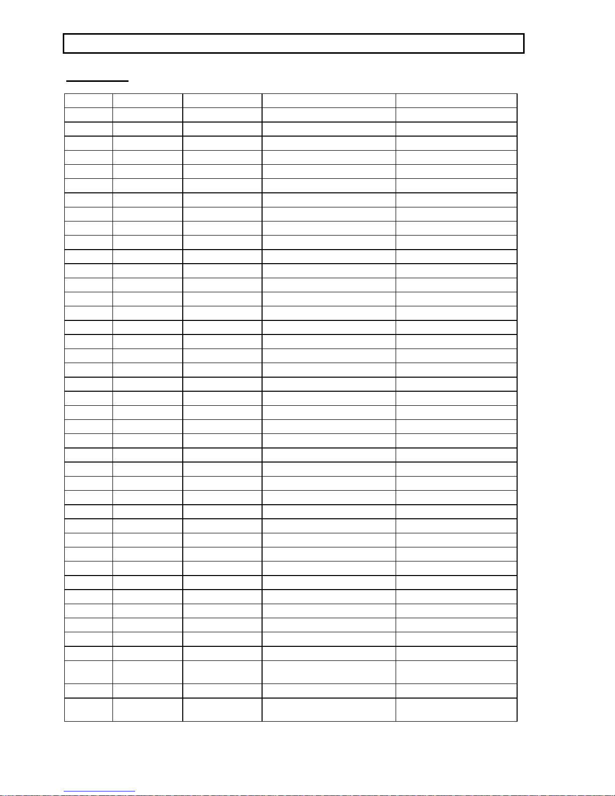
RESISTORS
R101 SMD0805 330R MF 1/8W 1%
R102 SMD0805 2.7k MF 1/8W 1%
R103 SMD0805 1k MF 1/8W 1%
R104 SMD0805 470R MF 1/8W 1%
R105 SMD0805 100k MF 1/8W 1%
R106 SMD0805 10k MF 1/8W 1%
R107 SMD0805 47k MF 1/8W 1%
R108 SMD0805 100k MF 1/8W 1%
R109 SMD0805 10k MF 1/8W 1%
R110 SMD0805 10k MF 1/8W 1%
R111 SMD0805 10k MF 1/8W 1%
R112 SMD0805 10k MF 1/8W 1%
R120 AXIAL0.5 4.7R MF 1/4W 5%
R121 AXIAL0.5 4.7R MF 1/4W 5%
R122 SMD0805 10k MF 1/8W 1%
R123 SMD0805 NOT FITTED
R124 SMD0805 NOT FITTED
R125 SMD0805 NOT FITTED
R126 SMD0805 NOT FITTED
R201 SMD0805 75R MF 1/8W 1%
R202 SMD0805 75R MF 1/8W 1%
R214 SMD0805 47R MF 1/8W 1%
R401 NOT FITTED
R402 SMD0805 75R MF 1/8W 1%
R403 SMD0805 75R MF 1/8W 1%
R404 SMD0805 75R MF 1/8W 1%
R405 SMD0805 47R MF 1/8W 1%
R406 SMD0805 47R MF 1/8W 1%
R407 SMD0805 270R MF 1/8W 1%
R408 SMD0805 100R MF 1/8W 1%
R409 SMD0805 47R MF 1/8W 1%
R410 SMD0805 47R MF 1/8W 1%
R411 SMD0805 47R MF 1/8W 1%
R412 SMD0805 47k MF 1/8W 1%
R413 SMD0805 47k MF 1/8W 1%
R414 SMD0805 47k MF 1/8W 1%
R415 SMD0805 47k MF 1/8W 1%
R416 SMD0805 47k MF 1/8W 1%
R417 SMD0805 47k MF 1/8W 1%
R422 SMD0805 2.2k MF 1/8W 1%
R423 SMD0805 1.4k MF 1/8W 1% Was originally 2.2k. Reduced to
improve input overload
R428 SMD0805 2.2k MF 1/8W 1%
R429 SMD0805 1.4k MF 1/8W 1% Was originally 2.2k. Reduced to
improve input overload

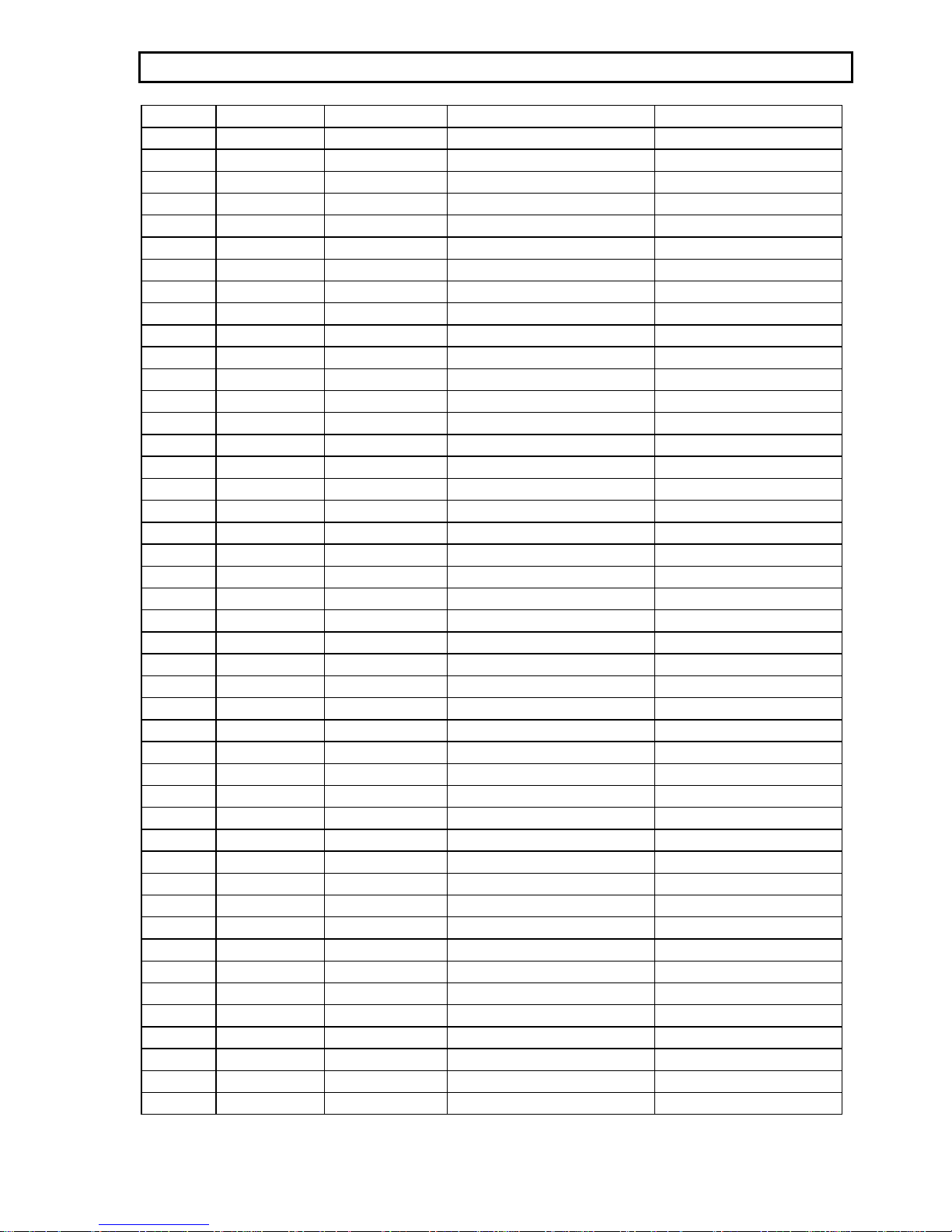
CYRUS AV5 PCB COMPONENTS
July 20007
R434 SMD0805 2.2k MF 1/8W 1%

CYRUS AV5 PCB COMPONENTS
July 2000 8
R435 SMD0805 1.4k MF 1/8W 1% Was originally 2.2k. Reduced to
improve input overload
R440 SMD0805 2.2k MF 1/8W 1%
R441 SMD0805 1.4k MF 1/8W 1% Was originally 2.2k. Reduced to
improve input overload
R446 SMD0805 2.2k MF 1/8W 1%
R447 SMD0805 1.4k MF 1/8W 1% Was originally 2.2k. Reduced to
improve input overload
R452 SMD0805 2.2k MF 1/8W 1%
R453 SMD0805 1.4k MF 1/8W 1% Was originally 2.2k. Reduced to
improve input overload
R501 SMD0805 47R MF 1/8W 1%
R502 SMD0805 100k MF 1/8W 1%
R503 SMD0805 5.6k MF 1/8W 1%
R504 SMD0805 47R MF 1/8W 1%
R505 SMD0805 47R MF 1/8W 1%
R506 SMD0805 47R MF 1/8W 1%
R601 SMD0805 100k MF 1/8W 1%
R602 SMD0805 100k MF 1/8W 1%
R603 SMD0805 100k MF 1/8W 1%
R604 SMD0805 100k MF 1/8W 1%
R605 SMD0805 100k MF 1/8W 1%
R606 SMD0805 100k MF 1/8W 1%
R607 SMD0805 5.1k MF 1/8W 1%
R608 SMD0805 5.1k MF 1/8W 1%
R609 SMD0805 5.1k MF 1/8W 1%
R610 SMD0805 5.1k MF 1/8W 1%
R611 SMD0805 5.1k MF 1/8W 1%
R612 SMD0805 3.6k MF 1/8W 1%
R613 SMD0805 10k MF 1/8W 1%
R614 SMD0805 10k MF 1/8W 1%
R615 SMD0805 10k MF 1/8W 1%
R616 SMD0805 10k MF 1/8W 1%
R617 SMD0805 10k MF 1/8W 1%
R618 SMD0805 7.5k MF 1/8W 1%
R619 SMD0805 2.2k MF 1/8W 1%
R620 SMD0805 2.2k MF 1/8W 1%
R621 SMD0805 2.2k MF 1/8W 1%
R622 SMD0805 2.2k MF 1/8W 1%
R623 SMD0805 2.2k MF 1/8W 1%
R624 SMD0805 2.2k MF 1/8W 1%
R625 SMD0805 2k MF 1/8W 1%
R626 SMD0805 2k MF 1/8W 1%
R627 SMD0805 2k MF 1/8W 1%
R628 SMD0805 2k MF 1/8W 1%
R629 SMD0805 2k MF 1/8W 1%
R630 SMD0805 2k MF 1/8W 1%
CYRUS AV5 PCB COMPONENTS
July 20009
R631 SMD0805 2.4k MF 1/8W 1%
R632 SMD0805 2.4k MF 1/8W 1%
R633 SMD0805 3k MF 1/8W 1%
R634 SMD0805 3k MF 1/8W 1%
R635 SMD0805 22k MF 1/8W 1%
R636 SMD0805 22k MF 1/8W 1%
R637 SMD0805 22k MF 1/8W 1%
R638 SMD0805 22k MF 1/8W 1%
R639 SMD0805 22k MF 1/8W 1%
R640 SMD0805 22k MF 1/8W 1%
R641 SMD0805 2.2k MF 1/8W 1%
R642 SMD0805 2.2k MF 1/8W 1%
R643 SMD0805 2.2k MF 1/8W 1%
R644 SMD0805 2.2k MF 1/8W 1%
R645 SMD0805 2.2k MF 1/8W 1%
R646 SMD0805 2.2k MF 1/8W 1%
R647 SMD0805 2.2k MF 1/8W 1%
R648 SMD0805 2.2k MF 1/8W 1%
R649 SMD0805 2.2k MF 1/8W 1%
R650 SMD0805 2.2k MF 1/8W 1%
R651 SMD0805 2.2k MF 1/8W 1%
R652 SMD0805 2.2k MF 1/8W 1%
R701 SMD0805 10k MF 1/8W 1%
R702 SMD0805 10k MF 1/8W 1%
R703 SMD0805 220R MF 1/8W 1%
R704 SMD0805 220R MF 1/8W 1%
R705 SMD0805 220R MF 1/8W 1%
R706 SMD0805 220R MF 1/8W 1%
R707 SMD0805 2.2k MF 1/8W 1%
R708 SMD0805 2.2k MF 1/8W 1%
R711 SMD0805 2.2k MF 1/8W 1%
R712 SMD0805 2.2k MF 1/8W 1%
R713 SMD0805 220R MF 1/8W 1%
R714 SMD0805 2.2k MF 1/8W 1%
R715 SMD0805 220R MF 1/8W 1%
R716 SMD0805 2.2k MF 1/8W 1%
R719 SMD0805 2.2k MF 1/8W 1%
R720 SMD0805 2.2k MF 1/8W 1%
R721 SMD0805 560R MF 1/8W 1%
R722 SMD0805 560R MF 1/8W 1%
R801 SMD0805 4.7k MF 1/8W 1%
R802 SMD0805 47R MF 1/8W 1%
R803 SMD0805 47R MF 1/8W 1%
R804 SMD0805 68k MF 1/8W 1%
R805 SMD0805 100k MF 1/8W 1%
R806 SMD0805 100k MF 1/8W 1%
 Loading...