

9439 IRONDALE AVE., CHATSWORTH, CALIFORNIA 91311 USA
www.cyron.com
Media Highlighter® IR Controller
HTW1000
Thank you for purchasing CYRON HTW1000 Media Highlighter IR
controller. Please follow all the steps to assure proper installation and
optimum usage of this device. It is a good idea to read through the
instructions once before you start your project.
Contents _____
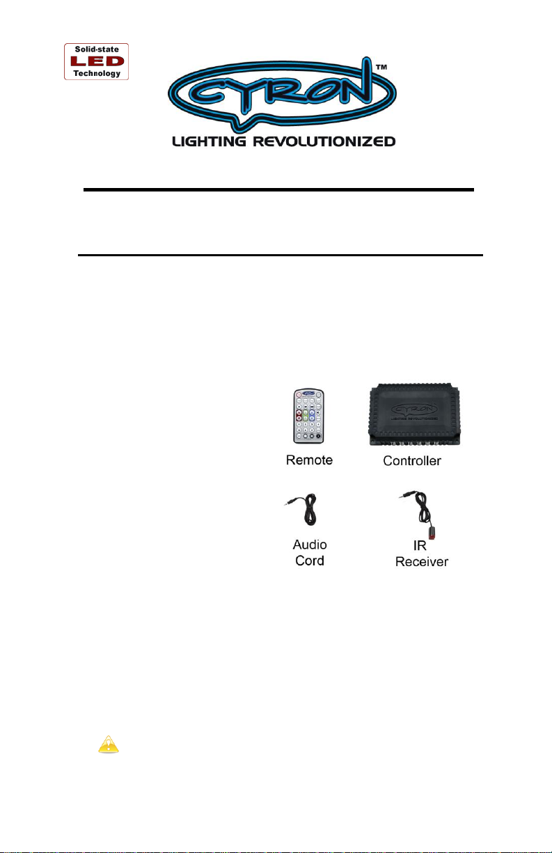
Please locate all system components. If any of the components are
missing or damaged contact CYRON before proceeding with
installation.
1 X Controller
1 X Remote control
1 X IR receiver
1 X Audio cord
4 X Mounting screws
Possibilities _____
CYRON HTW1000 is compatible with all Media Highlighter lights.
System is provided with 12 plugs for easy connections to Media
Highlighter Lightbars. For the ultimate expandability, the system is
also equipped with internal terminal blocks that allow hardwiring the
system without the use of connectors. By hardwiring, the system will
be able to handle much larger projects of up to 100 watts of light
output. For example, this would roughly equal to forty 15” lightbars
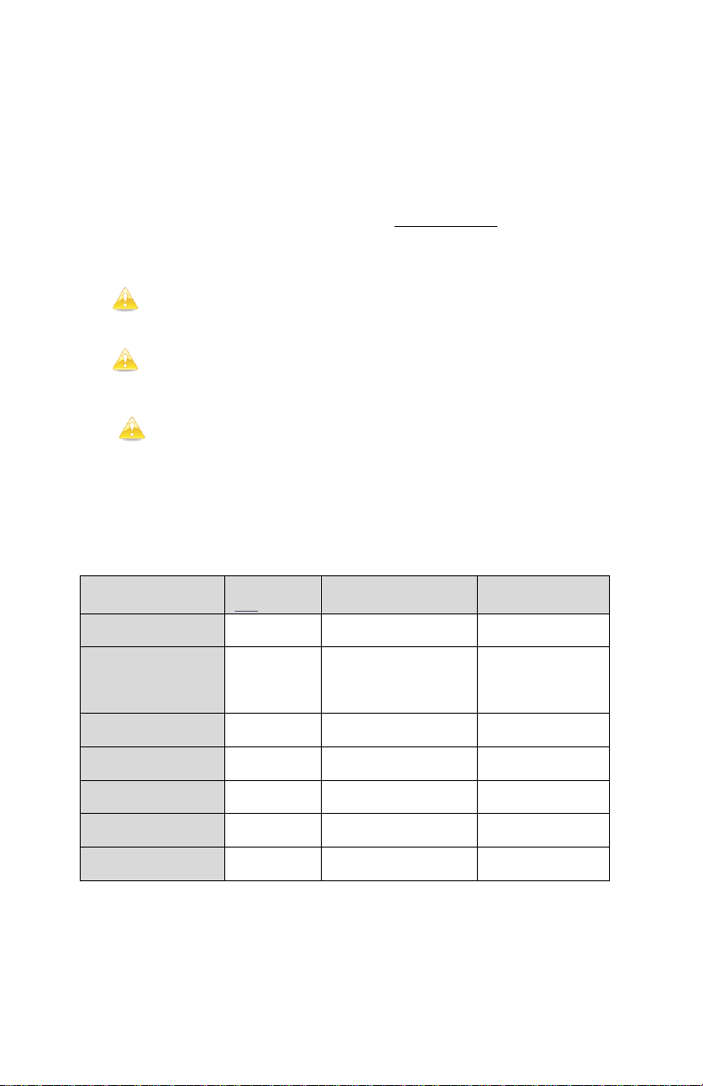
that can be connected to one HTW1000 controller! See Table One for
details.
Hardwiring needs ample knowledge of wiring practices and
should be done by experienced professionals such as electricians or
certified custom electronic installers. Please contact CYRON Technical
CYRON
Series/Size
Watts per
one lightbar
Model no. available
(Qty)
LEDs per bar /
Type of LED
HT (Standard) / 9”
1.44
HTB9 (2x9”)
18 / Superbright
60º
HT (Standard) / 15”
2.40
HTB15 (2x15”)
HTB15-B10 (10x15”)
HTB15-5B10 (10x15”)
5ft cords
30 / Superbright
60º
HTP (Pro) / 9”
1.20
HTPB9 (2x9”)
<limited qty>
15 / Ultrabright
SMD 120º
HTP (Pro) / 15”
2.16
HTPB15 (2x15”)
27 / Ultrabright
SMD 120º
HTP (Pro) / 24”
3.60
HTPB24 (2x24”)
45 / Ultrabright
SMD 120º
HTPR / 12”
2.20
HTPR-F
9 / Tri-chip
SMD 120º
HTPR / 16.5feet
36.00
HTPB-RL
150 / Tri-chip
SMD 120º
Support for further details.
Installations _____
CONTROLLER should preferably be installed out of sight, while
planning for the IR receiver to be installed in line of sight. REMOTE
needs to be pointed at the IR receiver for operation. Cautions and
Common practices:
Keep the controller and wires away from extreme heat,
liquids, and moving objects.
Low voltage wires can be routed through walls and cabinets as
long as proper care is taken to avoid damages.
DO NOT modify internal components. Tampering with
components and wiring will void factory warranty.
The CONTROLLER operates on 100% regulated 12VDC power. The
size (wattage) of the power supply depends on the number of lights.
Refer to Table One for calculating the power supply ratings:
__________ Table One __________

a Do not mix different types of CYRON lightbars in one area as
this will cause inconsistent colors. Color convergence of “HT” products
is different than HTP series.
There are two methods of connecting lights to the controller:
1. PLUG-n-PLAY lightbar connection
Connect the lightbars to controller plugs. Pay attention to the polarity
of the plugs. Do not use excessive force. The order in which they get
connected does not matter. You can plug as few as one or as many as
twelve. Use zip ties or other means to secure the wires together. This
will prevent the lightbar plugs from accidentally disconnecting.
CYRON supplies hub extender (part# HTH61) which provides 5 more
outlets for a total of 17 lightbars.
2. HARDWIRING Connecting more than 12 CYRON lightbars
You may choose this option if you are connecting more than 12
lightbars (17 with hub extender) or if lightbar cords are too short for
your project.
Hardwiring needs ample knowledge of wiring practices. This
option should be done by experienced professionals such as electricians
or certified custom electronic installers. Please contact CYRON
Technical Support for further details. There may be other options
available for your project. CYRON experienced Tech Support staff will
be happy to help you implement your project.
The hardwiring diagram can be requested by sending email to
techsupport@cyron.com.
Operations _____
The HTW1000 remote allows the ultimate control of the full color
spectrum. It has many features which may take some time to get
familiar with.
Power, Turn on
Power, Turn off
Pre-programmed Light show: Sequentially turns on/off seven
preset colors (colors cannot be changed).
Pre-programmed Light show: Color Transition. Gradually
changes color of light thru a preset color sequence.

Pre-programmed Light show: aka Breath mode. Sequentially
fades in and fades out seven preset colors (colors cannot be
changed).
Slow speed (60 seconds)
Medium speed (5 seconds)
Fast speed (1 second)
Dimming buttons do not operate in Light Shows
Stops the light show on the color displayed at that instance.

Turn-off timer. There are 5 timers of 1, 2, 3, 4 and 5 hours.
Each time the button is pressed the lights will flash according
to the number of hours.
>First press; lights flash once; system turns off in 1 hour.
>Second press; lights flash twice; system turns off in 2 hours.
>Third press; lights flash three times; system turns off in 3
hours. Same method applies for up to 5 hours.
Red, Green and Blue COLOR DIALS allow adjustment of
each color from zero brightness to full brightness in 50 steps.
The UP arrows increase and down arrows decrease the
brightness level of each particular color. By combining
different levels of each color there are more than 117,000
color combinations possible. Use COLOR DIALS to match
décor colors, create varies tones of white light, reduce the
brightness of colors or memorize custom colors of your own
in the MEMORY buttons.
COLOR DIALS only operate on memorized colors
and PAUSED colors.
You cannot press-and-hold to rapidly change thru the
50 steps. Buttons must be pressed once for each step.
SOUND MODE. The lights will interact with sound. Keep in
mind the microphone is placed inside the controller and
therefore picking up the ambient sound of where the controller
unit is placed. Alternatively, you may plug the line out of your
audio system in to the MIC input of HTW1000 controller. A
generic cord has been provided. Depending on your audio
system you may need a different type cable.
a DO NOT connect audio input of controller to speaker
outputs. Controller will be damaged.
Cool-White light preset.
Other tones of white can be achieved by COLOR
DIALS. In general, lowering the green and blue will
generate “warmer” tones of white.
Memory buttons 1 thru 7 can be used to memorize colors to be
recalled at any time. To memorize a color press the
button and then press the desired memory button 1 thru 7.

Dimming buttons allow you to dim any “memorized” or
“paused” light in 4 steps of 100%, 75%, 50% and 25%.
Dimming does not work for any light shows.
Dimming works best for memory buttons 1-7.
Dimming levels lower than 25% can be achieved by
first memorizing a color at 25% level. Then recalling
the color and dimming it again will result in lower
levels. Repeating this process can result in much
lower levels.
General Guidance _____
How to make a specific color:
It is best to start from a solid color that is close to the color you are
trying to get. For example, if you are trying to produce a specific shade
of sea green, it is best to start with solid green. If solid green is not one
of the colors in memory, one way would be to first press WHITE
button. Then, using COLOR DIALS press blue arrow up until blue
LEDs turn off. Press red arrow up until the red goes off. You should be
left with solid green. Now you can add blue color by pressing arrow up
to make the specific sea green you would like.
How to produce a color when watching a color show:
While watching any of the color shows you can press PAUSE button to
freeze the show on the color being displayed. A quick way to get to
some of the solid colors maybe to PAUSE the lights in the STEP mode.
Different tones of white light:
White light is presence of all primary colors. Otherwise, red green and
blue mixed together will make white light. However, what most
traditional lights produce is far from a “white” light. Depending on the
type of light, it could have a yellowish tone, bluish tone, or green tone.
Most people think of white light as yellowish white aka “warm white”.
A color similar to “warm white”, along with many other shades of
white, can be produced with CYRON HTW1000 controller. The
WHITE button produces a 100% red/green/blue combination.
Depending on the type of CYRON lights you use, this may produce a
shade of white that needs further adjustment. Generally, reducing green
and blue using COLOR DIALS will produce a warmer shade of white,
while reducing red will create a colder white. Play around with
COLOR DIALS and keep an open mind in what you may have known
as “white”.

Technical Support _____
CYRON’s primary goal is 100% customer satisfaction. You may call
our technical support line or contact us via email 24/7.
techsupport@cyron.com
888-297-6660 x106
In order to continually improve our products we welcome all comments
about the product you purchased.
Thank You!
Warranty _____
Cyron warrants this product against any defects in materials or workmanship for a period of ONE (1) year from the
date of purchase. The warranty covers normal usage as intended by the factory and does not cover misuse, abuse,
accidents, or damages caused due to the acts of God. Proof of purchase is required.
ANY IMPLIED WARRANTIES, INCLUDING WITHOUT LIMITATION THE IMPLIED WARRANTIES OF
MERCHANTABILITY AND FITNESS FOR A PARTICULAR PURPOSE, SHALL BE LIMITED TO THE
DURATION OF THIS LIMITED WARRANTY, OTHERWISE THE REPAIR, REPLACEMENT, OR REFUND AS
PROVIDED UNDER THIS EXPRESS LIMITED WARRANTY IS THE EXCLUSIVE REMEDY OF THE
CONSUMER, AND IS PROVIDED IN LIEU OF ALL OTHER WARRANTIES, EXPRESS OF IMPLIED. IN NO
EVENT SHALL CYRON, INC. BE LIABLE, WHETHER IN CONTRACT OR TORT (INCLUDING
NEGLIGENCE) FOR DAMAGES IN EXCESS OF THE PURCHASE PRICE OF THE PRODUCT, ACCESSORY
OR FOR ANY INDIRECT, INCIDENTAL, SPECIAL OR CONSEQUENTIAL DAMAGES OF ANY KIND, OR
LOSS OF REVENUE OR PROFITS, LOSS OF BUSINESS, OR OTHER FINANCIAL LOSS ARISING OUT OF OR
IN CONNECTION WITH THE ABILITY OR INABILITY TO USE THE PRODUCTS OR ACCESSORIES TO THE
FULL EXTENT THESE DAMAGES MAY BE DISCLAIMED BY LAW.
Some states and jurisdictions do not allow the limitation or exclusion of incidental or consequential damages, or
limitation on the length of an implied warranty, so the above limitations or exclusions may not apply to you. This
warranty gives you specific legal rights, and you may also have other rights that vary from state to state or from one
jurisdiction to another.
Please mail all warranty claims to:
CYRON, Inc.
HT Warranty Claim
9439 Irondale Ave.
Chatsworth, CA 91311 USA
Further warranty inquiries: warranty@cyron.com
 Loading...