


 Loading...
Cynergy™
OPERATOR MANUAL
850-1065-000, Rev. 6
 CYNOSURE®
5 Carlisle Road, Westford, MA, 01886, USA Phone: 978-256-4200 www.cynosurelaser.com
Distributors:
Cynosure, UK Ltd.
The Old Barn Offices
Lower Mount Farm, Long Lane
Cookham, Berkshire SL6 9EE
England
Telephone: 44-1628-522252
Telefax: 44-1628-520525
Cynosure France
86, Avenue Lenine
94250 Gentilly
France
Telephone: 33-1-49.85.6005
Telefax: 33-1-49.85.6004
Cynosure, GmbH.
Robert-Bosch-Strasse 11A
D-63225 Langen
Germany
Telephone: 49-6103-20111-00
Telefax: 49-6103-20111-11
Cynosure KK
Kasuga Business Center Bldg. 1F
1-15-15 Nishikata, Bunkyo-Ku
Tokyo 113-0024
Telephone: +81-3-5844-3651
Telefax: +81-3-5844-3652
Cynosure, Inc.
220 Tagore, #01-01/2
Liberty Warehouse
Singapore 787600
Telephone: 65-9988-4565
Telefax: 65-6853-4309
™Cynergy is a trademark of Cynosure, Inc.
®Cynosure is a registered trademark of Cynosure, Inc.
This manual is intended for both U.S. and international distribution. © 2005 Cynosure, Inc. All rights reserved.
Document #850-1065-000, Rev. 6, 6/06

Table of Contents
Glossary of Symbols and Abbreviations................................................................................. |
6 |
|
Section 1 |
Introduction....................................................................................................... |
7 |
About the Lasers ............................................................................................................. |
7 |
|
About the Manual ........................................................................................................... |
7 |
|
Section 2 |
Equipment Safety.............................................................................................. |
9 |
Potential Hazards ............................................................................................................ |
9 |
|
|
Optical Hazard .................................................................................................... |
9 |
|
Electrical Hazard............................................................................................... |
10 |
|
Chemical Hazard............................................................................................... |
10 |
|
Potential Chemical Accidents and Appropriate Responses.............................. |
10 |
|
Hot Water Hazard ............................................................................................. |
10 |
|
Laser-Induced Fire Hazard ............................................................................... |
11 |
|
Electromagnetic Compatibility Hazards........................................................... |
11 |
Laser Safety Features.................................................................................................... |
12 |
|
|
Key Switch........................................................................................................ |
12 |
|
Emergency Laser Stop ...................................................................................... |
12 |
|
Standby Mode ................................................................................................... |
12 |
|
Delayed Ready Mode........................................................................................ |
12 |
|
Automatic Shutdown Feature ........................................................................... |
13 |
|
Remote Interlock............................................................................................... |
13 |
|
Audible Tone .................................................................................................... |
13 |
|
Laser Warning Sign .......................................................................................... |
13 |
|
Locking Casters ................................................................................................ |
13 |
|
Device Labels ................................................................................................... |
14 |
|
Figure 1A–Device Labels in Position............................................................... |
14 |
|
Figure 1B–Device Labels Used ........................................................................ |
15 |
Section 3 |
Site Preparation .............................................................................................. |
17 |
Spatial Requirements .................................................................................................... |
17 |
|
Electrical Requirements................................................................................................ |
17 |
|
Environmental Requirements........................................................................................ |
18 |
|
Storage and Transport Requirements............................................................................ |
18 |
|
Disposal of Waste Electrical and Electronic Equipment .............................................. |
18 |
|
Cynergy Operator Manual |
850-1065-000, Rev. 6 |
Page 1 of 78 |

Section 4 |
Laser Description............................................................................................ |
19 |
Main Components......................................................................................................... |
19 |
|
|
Figure 2A–Main Components, Front................................................................ |
19 |
|
Figure 2B–Main Components, Inside Front Door ............................................ |
20 |
|
Figure 2C–Main Components, Rear View........................................................ |
21 |
|
Figure 2D–Main Components, Right Side from Rear ...................................... |
22 |
|
Key Switch........................................................................................................ |
22 |
Handpieces and Delivery Optical Fiber........................................................................ |
23 |
|
|
Connecting the Optical Fiber............................................................................ |
23 |
|
Changing Handpieces ....................................................................................... |
23 |
|
Figure 3–Handpiece.......................................................................................... |
24 |
|
Trigger Switches ............................................................................................... |
24 |
Front Control Panel....................................................................................................... |
25 |
|
|
Figure 4–Front Control Panel ........................................................................... |
25 |
|
Emergency Laser Stop ...................................................................................... |
25 |
|
Cal Port ............................................................................................................. |
25 |
|
Display .............................................................................................................. |
25 |
Display Screens............................................................................................................. |
26 |
|
|
Home Screen..................................................................................................... |
26 |
|
Figure 5A–Home Screen................................................................................... |
26 |
|
Treatment Screens............................................................................................. |
27 |
|
Figure 5B–PDL Screen..................................................................................... |
27 |
|
Figure 5C–YAG Screen.................................................................................... |
27 |
|
Treatment Screen Elements .............................................................................. |
28 |
|
Figure 5D–Laser Screen Elements ................................................................... |
28 |
|
MultiPlex Treatment Screen ............................................................................. |
30 |
|
Figure 5E–MultiPlex Laser Screen................................................................... |
30 |
|
Utility Screen .................................................................................................... |
31 |
|
Figure 5F–Utility Screen .................................................................................. |
31 |
|
Option Screen ................................................................................................... |
33 |
|
Figure 5G–Option Screen ................................................................................. |
33 |
System Specifications ................................................................................................... |
34 |
|
|
General Specifications ...................................................................................... |
34 |
Fluence Specifications .................................................................................................. |
35 |
|
|
Cynergy PDL .................................................................................................... |
35 |
|
Cynergy YAG ................................................................................................... |
36 |
|
Cynergy MultiPlex Option................................................................................ |
37 |
Page 2 of 78 |
850-1065-000, Rev. 6 |
Cynosure, Inc. |

Section 5 |
Laser Operation .............................................................................................. |
39 |
Laser Start-Up............................................................................................................... |
39 |
|
Laser Shutdown ............................................................................................................ |
39 |
|
Laser Calibration........................................................................................................... |
40 |
|
Energy Regulation During Treatment........................................................................... |
40 |
|
Laser Operation............................................................................................................. |
41 |
|
Changing Treatment Parameters................................................................................... |
41 |
|
Section 6 |
Clinical Application–YAG ............................................................................. |
43 |
Laser Operator Training Requirements–YAG.............................................................. |
43 |
|
Indications, Contraindications and Adverse Effects–YAG .......................................... |
44 |
|
|
Indications......................................................................................................... |
44 |
|
Contraindications .............................................................................................. |
44 |
|
Adverse Effects................................................................................................. |
44 |
Pretreatment Recommendations–YAG......................................................................... |
45 |
|
|
Determine Suitability........................................................................................ |
45 |
|
Inform Patient About the Treatment................................................................. |
45 |
|
Photographs ...................................................................................................... |
45 |
Treatment Recommendations–YAG............................................................................. |
46 |
|
|
Minimizing Adverse Effects............................................................................. |
46 |
|
Setting Energy Level ........................................................................................ |
46 |
|
Number and Length of Treatment Sessions...................................................... |
46 |
|
Determining End of Treatment ......................................................................... |
46 |
Posttreatment Recommendations–YAG ....................................................................... |
46 |
|
Section 7 |
Clinical Application–PDL .............................................................................. |
47 |
Laser Operator Training Requirements–PDL............................................................... |
47 |
|
Indications, Contraindications and Adverse Effects–PDL ........................................... |
48 |
|
|
Indications......................................................................................................... |
48 |
|
Contraindications .............................................................................................. |
48 |
|
Adverse Effects................................................................................................. |
48 |
Patient Selection–PDL.................................................................................................. |
48 |
|
Pretreatment Recommendations–PDL.......................................................................... |
49 |
|
|
Determine Suitability........................................................................................ |
49 |
|
Inform Patient About the Treatment................................................................. |
49 |
|
Photographs ...................................................................................................... |
49 |
Treatment Recommendations–PDL.............................................................................. |
50 |
|
|
Minimizing Adverse Effects............................................................................. |
50 |
|
Setting Energy Level ........................................................................................ |
50 |
Cynergy Operator Manual |
850-1065-000, Rev. 6 |
Page 3 of 78 |

|
Number and Length of Treatment Sessions...................................................... |
50 |
|
Determining End of Treatment ......................................................................... |
50 |
Posttreatment Recommendations–PDL ........................................................................ |
50 |
|
Section 8 |
Clinical Application–MultiPlex Option ........................................................ |
51 |
Laser Operator Training Requirements–MultiPlex ...................................................... |
51 |
|
Indications, Contraindications and Adverse Effects–MultiPlex................................... |
52 |
|
|
Indications......................................................................................................... |
52 |
|
Contraindications .............................................................................................. |
52 |
|
Adverse Effects................................................................................................. |
52 |
Patient Selection–MultiPlex ......................................................................................... |
52 |
|
Pretreatment Recommendations–MultiPlex ................................................................. |
53 |
|
|
Determine Suitability........................................................................................ |
53 |
|
Inform Patient About the Treatment................................................................. |
53 |
|
Photographs ...................................................................................................... |
53 |
Treatment Recommendations–MultiPlex ..................................................................... |
54 |
|
|
Minimizing Adverse Effects............................................................................. |
54 |
|
Setting Energy Level ........................................................................................ |
54 |
|
Number and Length of Treatment Sessions...................................................... |
54 |
|
Determining End of Treatment ......................................................................... |
54 |
Posttreatment Recommendations–MultiPlex................................................................ |
54 |
|
Section 9 |
Maintenance .................................................................................................... |
55 |
Cleaning and Disinfecting Equipment.......................................................................... |
55 |
|
Adding Water to the Reservoir ..................................................................................... |
55 |
|
Dye Kit Methodology ................................................................................................... |
56 |
|
|
Dye Injection..................................................................................................... |
56 |
Replacing the Dye Kit................................................................................................... |
57 |
|
|
Figure 6A–Disconnecting and Removing Dye Filter ....................................... |
57 |
|
Figure 6B–Detaching/Inserting Dye Inject Bottle............................................ |
58 |
Troubleshooting ............................................................................................................ |
59 |
|
|
Faults................................................................................................................. |
59 |
|
Fault Code Table............................................................................................... |
59 |
|
Self Test ............................................................................................................ |
61 |
|
Troubleshooting Chart ...................................................................................... |
62 |
|
Transferring Diagnostic Data............................................................................ |
63 |
|
Figure 7A–USB Access Panel Location........................................................... |
63 |
|
Figure 7B–USB Slot Location.......................................................................... |
64 |
Page 4 of 78 |
850-1065-000, Rev. 6 |
Cynosure, Inc. |

Section 10 |
Customer Support........................................................................................... |
65 |
Direct-Purchase Warranty............................................................................................. |
65 |
|
Distributor-Purchased Warranty ................................................................................... |
65 |
|
Warranty Claims ........................................................................................................... |
65 |
|
Installation .................................................................................................................... |
66 |
|
Customer Service.......................................................................................................... |
66 |
|
|
Scope of Service ............................................................................................... |
66 |
|
Contacting Customer Service ........................................................................... |
66 |
Appendix A |
Service Calibration ......................................................................................... |
67 |
Schedule for Calibration ............................................................................................... |
67 |
|
Overview....................................................................................................................... |
67 |
|
Required Equipment ..................................................................................................... |
68 |
|
Calibration Procedures.................................................................................................. |
68 |
|
Calibrating the Resonator Port, YAG ........................................................................... |
69 |
|
Calibrating the Resonator Port, PDL ............................................................................ |
70 |
|
Calibrating the Cal Port, YAG...................................................................................... |
71 |
|
Calibrating the Cal Port, PDL....................................................................................... |
72 |
|
Appendix B |
Electromagnetic Compatibility...................................................................... |
73 |
Appendix C Declaration of Conformity ............................................................................. |
77 |
|
Cynergy Operator Manual |
850-1065-000, Rev. 6 |
Page 5 of 78 |
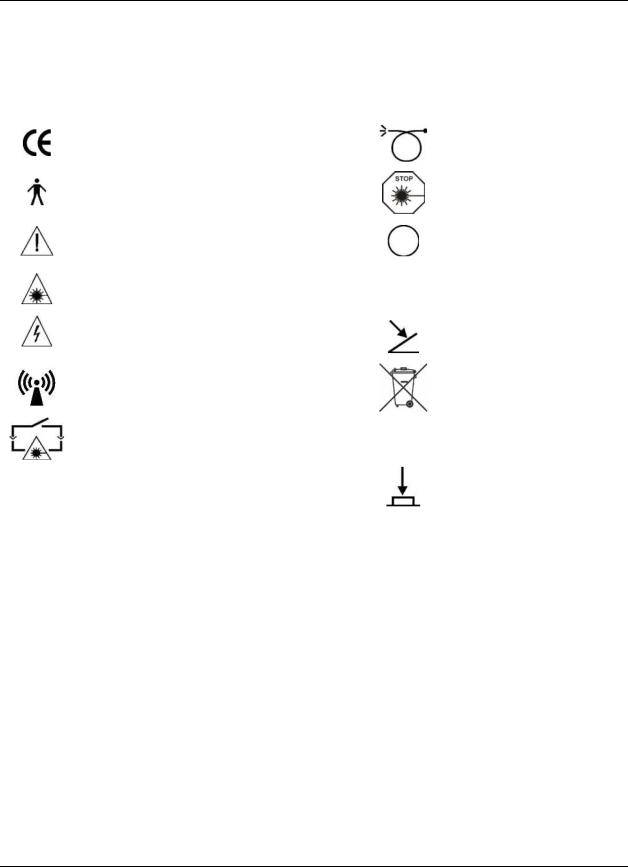
Glossary of Symbols and Abbreviations
The following symbols and abbreviations may be used on the Cynergy laser and/or in this manual.
Symbols |
|
Declaration of Conformity to |
|
Medical Device Directive 93/42/EEC |
|
CE Mark to Directive 93/465/EEC |
|
Type B applied part per EN60601-1: 1990 |
|
Attention, consult accompanying documents |
|
Laser Hazard Warning |
|
Dangerous Voltage |
|
Non-ionizing Radiation |
|
Remote Interlock Connector per |
Other |
EN60601-2-22: 1996 |
Symbols |
Optical Fiber Applicator per EN60601-2-22: 1996
Emergency Laser Stop per EN60601-2-22: 1996
Off—power disconnection from mains
On—power connection to mains
Foot Switch
WEEE symbol per EN50419
Hand Switch
|
|
Abbreviations |
|
°C |
Degrees Celsius |
V |
Volts |
A |
Amperes |
DVM |
Digital Voltmeter |
mA |
Milliamp |
Hz |
Hertz |
µA |
Microamp |
J |
Joule |
AC |
Alternating Current |
J/cm² |
Joule per square centimeter |
cm |
Centimeter |
kW |
Kilowatt |
mm |
Millimeter |
ms |
Millisecond |
nm |
Nanometer |
Ω |
Ohms |
CW |
Continuous Wave |
mΩ |
Milliohms |
Page 6 of 78 |
850-1065-000, Rev. 6 |
Cynosure, Inc. |

Section 1 |
Introduction |
About the Lasers
The Cynergy laser combines two lasers—a high-powered pulse dye laser (PDL) and a Nd:YAG laser—into one unit with a common delivery system. The result is a multi-application dermatological laser that treats small red vessels, scars, rosacea, vascular lesions and sundamaged skin using the pulse dye wavelength, as well as treating larger facial and leg veins, vascular lesions, and unwanted hair on all skin types using the YAG wavelength. The laser is also available with the Cynergy MultiPlex option that combines both wavelengths in a single pulse offering improved clinical outcome. This manual addresses both lasers including the MultiPlex option.
The laser is designed to effectively couple the laser energy directly to the target while leaving the surrounding tissue unharmed. This principle is known as Selective Photothermolysis (SPT). By careful selection of the wavelength, pulse width, spot size, energy and cooling method, the effectiveness of the laser on the target is maximized, while any heating to surrounding tissue is minimized. Thermokinetic Selectivity®, or TKS®, is a corollary of SPT. It uses a laser pulse width that is much longer than the thermal relaxation time of small surrounding structures, yet less than the thermal relaxation time of the large target. This allows the small surrounding structures to remain cool while the larger target heats up to the destruction point.
The Cynergy with Multiplex™ Option, which allows treatment with both PDL and YAG in a single pulse, further exploits the principles of SPT and TKS for maximum efficacy in the treatment of cutaneous vascular lesions.
About the Manual
The Cynergy Operator Manual provides the following information about the laser:
♦Equipment Safety
♦Site Preparation
♦Laser Operation
♦Maintenance
♦Customer Support
♦Storage and Transport
Although the manual provides useful information on the use and maintenance of the laser, it is not intended to be a complete guide. Cynosure suggests that all health care professionals who plan to use the laser seek further training in its proper use. The custodian of the laser shall take steps to prevent its unauthorized use.
CAUTION: Use of controls or adjustments or performance of procedures other than those specified herein may result in hazardous radiation exposure.
® Thermokinetic Selectivity and TKS are registered trademarks of Cynosure, Inc. / Cynergy with Multiplex is a trademark of Cynosure, Inc.
Cynergy Operator Manual |
850-1065-000, Rev. 6 |
Page 7 of 78 |

This page has been intentionally left blank.
Page 8 of 78 |
850-1065-000, Rev. 6 |
Cynosure, Inc. |
Section 2 |
Equipment Safety |
Potential Hazards
As with any equipment, there are potential hazards. Before using the laser, operators should be aware of the following types of hazards: optical, electrical and combustible. This section of the manual describes these potential hazards and suggests precautions. This section also describes safety features designed to minimize potential hazards.
Optical Hazard
The laser emits an intense energy beam of invisible and visible laser light radiation that can cause serious eye damage with direct or even indirect optical contact.
WARNING: Always wear the protective eyewear supplied with the laser system. Failure to wear the appropriate protective eyewear can result in serious eye injury.
Please follow these precautions to avoid optical damage to laser operators, assisting personnel and patients.
♦All persons in the room during treatment must wear the protective eyewear recommended by Cynosure. See “System Specifications” starting on page 34 for recommendations.
♦Never look directly into the handpiece, fiber or fiber opening, even while wearing protective eyewear.
♦Mark treatment rooms with the laser warning signs to avoid unnecessary personnel entering room during treatment.
♦Limit entry to the treatment room only to personnel who are assisting in treatment and are trained in the use of the equipment.
♦Cover windows and other openings in the treatment room to avoid the inadvertent escape of laser light.
♦Direct the activated laser only at the intended area of treatment.
♦Place one person in charge of the laser system’s controls during the treatment.
♦Cover reflective objects, such as jewelry or mirrors, which could deflect the laser beam to an area other than the intended treatment area.
♦Put the laser into Standby Mode when the laser is not in use. When in Standby Mode, the laser beam cannot be inadvertently activated.
♦Ensure that all appropriate staff members are trained to shut off the laser in the case of an emergency.
♦Keep the laser start-up key in a safe place outside of the treatment room when the laser is not in use.
Cynergy Operator Manual |
850-1065-000, Rev. 6 |
Page 9 of 78 |

Electrical Hazard
The laser system uses high voltage. Do not open the protective panels unless you are trained and authorized to do so.
Chemical Hazard
The Cynergy laser uses a dye medium. Handle the dye with care, both to protect against toxicity and against staining. Operators should follow these precautions:
♦Wear rubber or plastic gloves when handling the dye.
♦Do not dispose of dye down drains.
♦Return empty dye bottles and used filters to Cynosure.
♦Avoid spillage on fabrics or on any porous material.
Potential Chemical Accidents and Appropriate Responses
The following table lists potential chemical accidents and their appropriate emergency responses.
Chemical Accident |
Appropriate Emergency Response |
Ingestion of dye or solvent |
Drink water, induce vomiting, and seek immediate |
|
medical attention. |
Excessive inhalation of dye or solvent |
Go outdoors and inhale fresh air. |
|
Seek medical attention if symptoms appear. |
Eyes exposed to dye or dye solvent |
Rinse eyes with water. |
|
Seek medical attention if symptoms appear. |
Skin exposed to dye or dye solvent |
Immediately wash the exposed skin area with plain |
|
water, then with soap and water. |
Hot Water Hazard
The laser uses water cooling to maintain the system at its proper operating temperature. This water can become very hot (greater than 50 ºC) and could scald. Do not perform any maintenance on the water system while hot. Always let the system cool down before changing the deionizing filter or adding deionized or distilled water.
Page 10 of 78 |
850-1065-000, Rev. 6 |
Cynosure, Inc. |

Laser-Induced Fire Hazard
When the laser beam contacts an exterior surface, that surface can absorb the laser energy. This raises the surface temperature, whether the surface is skin, hair, clothes or any flammable substance. Operators should take the following precautions to prevent a laser-induced fire:
♦Use non-flammable substances for uses such as anesthesia, skin preparation, and cleaning or disinfecting instruments.
♦Be especially careful with the use of oxygen. Oxygen accelerates both the severity and the extent of a fire.
♦Keep a minimum of combustible materials (e.g., alcohol) in the treatment room. If treatment requires the use of gauze, first soak it in water.
♦Always keep a small fire extinguisher and water in the treatment room.
Electromagnetic Compatibility Hazards
The Cynergy laser has special precautions regarding electromagnetic compatibility hazards (EMC), and need to be installed and operated according to the EMC information provided in Appendix B, starting on page 73 of this manual.
CAUTION: Portable and mobile radio frequency (RF) communication equipment can affect the Cynergy laser.
CAUTION: The Cynergy laser should not be used adjacent to, or stacked with, other equipment other than the Cynergy PL system. If the laser must be used adjacent to, or stacked with other equipment, then observe the laser in its configuration to verify that operation is normal.
Cynergy Operator Manual |
850-1065-000, Rev. 6 |
Page 11 of 78 |

Laser Safety Features
The laser offers several safety features to prevent its misuse or unintentional activation. All personnel who operate the laser or assist in the operation should be familiar with these safety features.
Key Switch
The Key Switch controls the electrical activation of the laser system. Only those authorized personnel who have access to the key can start the laser system. Keep the laser start key in a secure location to prevent use by unauthorized personnel.
Emergency Laser Stop
The Emergency Laser Stop is a dedicated override switch for immediate shut down of the laser system.
Standby Mode
Standby Mode is designed to prevent unintentional or accidental activation of the laser. The system enters Standby Mode when the operator presses the Standby Key on the touch screen, or when laser is selected from the Home screen at start up. The laser status is displayed on the upper-left part of the screen.
When the laser is in Standby Mode, the system is on but the operator cannot activate the laser beam without first pressing the Ready Key on the touch panel.
Delayed Ready Mode
From Standby Mode, press the Ready Key to activate the laser. As required by the Center for Devices and Radiological Health of the U.S. Food and Drug Administration and International Standards (IEC601-2-22 and 825-1), there is a 3-second delay from the time the Ready Key
is pressed until the laser can be activated. This delay, during which there is an audible beep and the ready key is lit, provides time for personnel to prepare before the beginning of treatment.
Page 12 of 78 |
850-1065-000, Rev. 6 |
Cynosure, Inc. |

Automatic Shutdown Feature
When certain faults occur, the laser automatically shuts down and a fault code, message and corrective action is displayed. For a complete list of faults and failure analysis information, see “Troubleshooting,” starting on page 59.
Remote Interlock
Cynosure provides a remote interlock circuit that can connect to a door switch of a treatment room. When the remote interlock is wired in series with a door switch, the laser automatically shuts down if anyone enters the treatment room. Contact Cynosure for detailed instructions on how to implement this function.
Audible Tone
Laser emission is indicated by a pulsed tone for the period of the emission.
Laser Warning Sign
Cynosure supplies a laser warning sign with each laser system. We recommend posting the sign at all entrances to rooms with an operating laser. Please check the policy of your hospital or clinic.
Locking Casters
The front casters of the laser may be locked into place. On the top of the front casters is a locking lever. To lock the casters, press down on the front of the lever. To release the casters, lift the lever into the original horizontal position.
Cynergy Operator Manual |
850-1065-000, Rev. 6 |
Page 13 of 78 |

Device Labels
The Cynergy laser comes with a series of required safety labels. Be sure that all personnel are familiar with these labels and their meanings.
Figure 1A–Device Labels in Position
Page 14 of 78 |
850-1065-000, Rev. 6 |
Cynosure, Inc. |

Figure 1B–Device Labels Used
Cynergy Operator Manual |
850-1065-000, Rev. 6 |
Page 15 of 78 |

This page has been intentionally left blank.
Page 16 of 78 |
850-1065-000, Rev. 6 |
Cynosure, Inc. |

Section 3 |
Site Preparation |
When preparing the laser site, operators should consider the spatial, electrical, environmental, transportation and storage requirements of the laser unit.
Spatial Requirements
The Cynergy and Cynergy III systems, which include the Cynergy Pulse Light (PL) system, have the following dimensions:
|
Cynergy Laser |
Cynergy III |
|
Cynergy w/Cynergy PL |
|
|
|
|
|
|
|
Height: |
40" (101 cm) |
48" (121 cm) |
|
|
|
Width: |
18" (46 cm) |
19" (48 cm) |
|
|
|
Depth |
31" (79 cm) |
31" (79 cm) |
|
|
|
Weight |
270 lbs (123 kg) |
310 lbs (141 kg) |
|
|
|
For more information on the pulse light system, please refer to the Cynosure PL Operator Manual.
Electrical Requirements
Please consider the following electrical requirements before installing the laser unit: ♦ The AC line power requirements for the laser are:
200-240 VAC, Single Phase
30 Amps
50-60 Hz
♦The plug is NEMA L6-30.
♦Power receptacles must be within 15 feet of the laser site.
♦The power receptacle must be grounded.
♦The laser should not share a power line with other heavy power-load equipment such as air conditioners or elevators. Ideally, the laser unit should be on a separate power line with a separate circuit breaker.
Cynergy Operator Manual |
850-1065-000, Rev. 6 |
Page 17 of 78 |

Environmental Requirements
Follow these environmental requirements to properly maintain the laser system.
♦Keep the air free of corrosive substances, such as salts and acids. These pollutants may damage electrical wiring and optical surfaces.
♦Keep dust and hair particles to a minimum. Shave patient’s skin in a separate room. Dust and hair particles can cause permanent damage to optical components.
♦Keep humidity in the laser room at 20% to 80%, non-condensing.
♦Keep the laser room temperature from 50° to 80° F (10° to 27°C).
♦Do not place laser unit near heating vents or other sources of temperature variation. NOTE: Most of the heat that is dissipated by the laser exits the rear panel.
Storage and Transport Requirements
To maintain the laser system properly during storage and transport, follow these requirements.
♦Keep the ambient temperature between 40° and 110° F (4° to 43° C).
♦Keep the laser system in a location where the humidity is between 10% and 90%, noncondensing.
♦Lift only with suitable and appropriate equipment.
♦Minimize shock and vibration.
♦Do not drop.
♦Store the laser system where the air is free of corrosive substances, such as salts or acids.
♦Store the laser system where there is a minimum of dust particles.
♦When storing or transporting the laser in temperatures less than 40° F (4° C), the laser coolant system must be drained. This is a highly complex process and should be performed by a trained service technician. Please contact Cynosure Customer Service, as detailed on page 66 to arrange for a service call.
Disposal of Waste Electrical and Electronic Equipment
To comply with European Commission Directive 2002/96/EC on Waste Electrical and Electronic Equipment (WEEE) and other country and state regulations, please DO NOT dispose of this laser equipment in any location other than designated locations.
Page 18 of 78 |
850-1065-000, Rev. 6 |
Cynosure, Inc. |
Section 4 |
Laser Description |
This section of the manual gives a general description of the laser including the system’s specifications.
Main Components
Refer to Figures 2A and 2B to identify the main components of the laser system.
Figure 2A–Main Components, Front
Cynergy Operator Manual |
850-1065-000, Rev. 6 |
Page 19 of 78 |
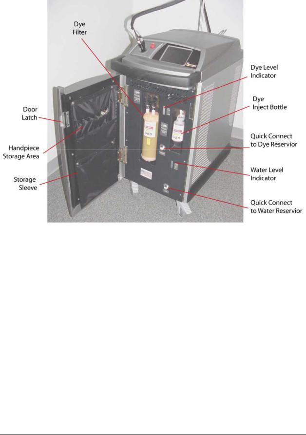
Figure 2B–Main Components, Inside Front Door
Page 20 of 78 |
850-1065-000, Rev. 6 |
Cynosure, Inc. |
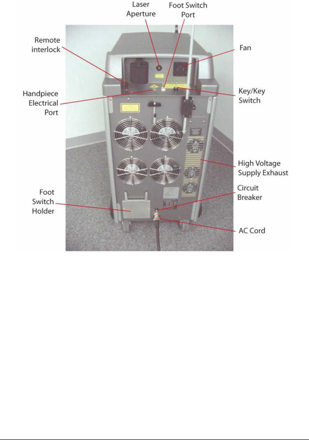
Figure 2C–Main Components, Rear View
Cynergy Operator Manual |
850-1065-000, Rev. 6 |
Page 21 of 78 |
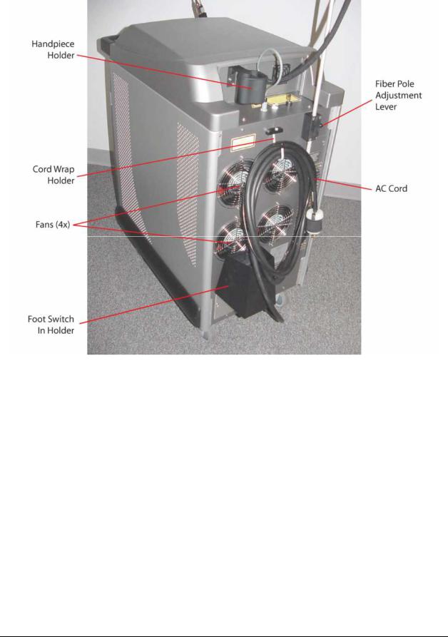
Figure 2D–Main Components, Right Side from Rear
Key Switch
The key switch and key turn the system on and off. There are two positions on the switch: ON ( | ) and OFF (○). To turn the laser on, insert the key and turn the key switch to the start position. Always remove the key after use to prevent access by unauthorized users.
Page 22 of 78 |
850-1065-000, Rev. 6 |
Cynosure, Inc. |
Loading...