

CYLINDA IM 91MG RFS Extended Technical Drawing
0
593
0°
382
595
544
20
21
14
348
320
299
80
0
0
0
-
300
300
0
560-
568
363
-
360
363
568
568
-
360

IM 91MG RFS
12NC/Fx: 859991548590 GTIN (EAN) code:
7392186307459
DIMENSION MEASURE
OVERALL CABINET
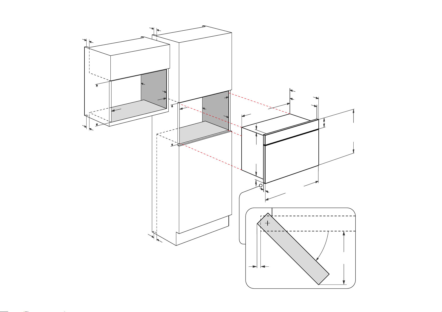
MIN Height of the wall cabinet niche, including all required space for installation or ventilation 360 mm
MIN Height of the tall cabinet niche, including all required space for installation or ventilation 360 mm
MIN Height of the base cabinet niche, including all required space for installation or ventilation 0 mm
MAX Height of the wall cabinet niche, including all required space for installation or ventilation 363 mm
MAX Height of the tall cabinet niche, including all required space for installation or ventilation 363 mm
MAX Height of the base cabinet niche, including all required space for installation or ventilation 0 mm
MIN Width of the wall cabinet niche, including all required space for installation or ventilation 568 mm
MIN Width of the tall cabinet niche, including all required space for installation or ventilation 560 mm
MIN Width of the base cabinet niche, including all required space for installation or ventilation 0 mm
MAX Width of the wall cabinet niche, including all required space for installation or ventilation 568 mm
MAX Width of the tall cabinet niche, including all required space for installation or ventilation 568 mm
MAX Width of the base cabinet niche, including all required space for installation or ventilation 0 mm
MIN Depth of the wall cabinet niche, including all required space for installation or ventilation 300 mm
MIN Depth of the tall cabinet niche, including all required space for installation or ventilation 300 mm
MIN Depth of the base cabinet niche, including all required space for installation or ventilation 0 mm
Space in front, which is required to install bottom trim 0 mm
Indicates whether a ventilation opening is needed or not. Default is "N" No
WALL CABINET (vent-shaft incoming)
Indicates the position of the freespace for the inbound airflow (wall cabinet) -
Minimum space or inbound ventilation (wall cabinet) 0 mm
Minimum area for inbound ventilation cavity (wall cabinet) 0 cm²
WALL CABINET (vent-shaft outgoing)
Indicates the position of the freespace for the outbound airflow (wall cabinet) -
Minimum space or outbound ventilation (wall cabinet) 0 mm
Minimum area for outbound ventilation cavity (wall cabinet) 0 cm²
TALL CABINET (vent-shaft incoming)
Indicates the position of the freespace for the inbound airflow (tall cabinet) -
Minimum space for inbound ventilation (tall cabinet) 0 mm
Minimum area for inbound ventilation cavity (tall cabinet) 0 cm²
TALL CABINET (vent-shaft outgoing)
Indicates the position of the freespace for the outbound airflow (tall cabinet) -
Minimum space for outbound ventilation (tall cabinet) 0 mm
Minimum area for outbound ventilation cavity (tall cabinet) 0 cm²
BASE CABINET (vent-shaft incoming)
Indicates the position of the freespace for the inbound airflow (base cabinet) -
Minimum space for inbound ventilation (base cabinet) 0 mm
Minimum area for inbound ventilation cavity (base cabinet) 0 cm²
BASE CABINET (vent-shaft outgoing)
Indicates the position of the freespace for the outbound airflow (base cabinet) -
Minimum space for outbound ventilation (base cabinet) 0 mm
Minimum area for outbound ventilation cavity (base cabinet) 0 cm²
DIMENSION MEASURE
APPLIANCE
Height of the front 382 mm
Width of the front 595 mm
Depth of the front 21 mm
Maximum depth all protruding elements, e.g. handles, controls 0 mm
Lateral clearance between front edge and most protruding elements which avoid to open a
neighbour front more than 90 degrees
Projection of front in relation to housing of appliance 20 mm
Projection of front in relation to bearing area of the appliance. Taken at minimum height of
appliance, if height is adjustable
When product panel is missing, set to 0 80 mm
Space in front, which is required to guarantee full operability. The most protruding part gives this
dimension
Height from bearing area of appliances and lower handle 0 mm
Frontal handle thickness 0 mm
Frontal handle width 0 mm
MIN Height of the product body 348 mm
MAX Height of the product body 348 mm
Width of the product body 544 mm
Depth of the product body 299 mm
Full depth of product excluding protruding interface elements 320 mm
Minimum height from bottom line hood to top line air outlet 0 mm
Maximum height from bottom line hood to top line air outlet 0 mm
Diameter minimum air outlet 0 mm
Diameter maximum air outlet 0 mm
Indicates measure between center of air outlet hole and rear wall 0 mm
Projection of the rear flap in relation to bearing area 0 mm
Height tube connection for air outlet 0 mm
Appliance can be used as base for other appliances from the same manufacturer. Default is "No" -
Appliance Flap door
Projection of the opened flap in relation to bearing area 0 mm
Maximum angle when flap door is opened totally 0 mm
Appliance Side swing door
Lateral projection of front incl. controls when door is opened totaly. At the side where the hinge is
mounted
Lateral projection of opened front at the side where the hinge is fixed 2 mm
Maximum angle when door is opened totally 85 mm
Appliance other
Depth from front end of the niche to the front end of the freespace of the retrace 0 mm
Height from niche to bottom end of freespace for the retrace 0 mm
0 mm
14 mm
593 mm
0 mm
 Loading...