

CyClone COMPACTPCI-824 FEP BLADE INTELLIGENT I/O CONTROLLER User Manual

COMPACTPCI-824
FEP BLADE INTELLIGENT
I/O CONTROLLER
USER’ S MANUAL
The information in this document has been carefully checked and is believed to be entirely reliable. However, no
responsibility is assumed for inaccuracies. Furthermore, Cyclone Microsystems, Inc. reserves the right to make
changes to any products herein to improve reliability, function, or design. Cyclone Microsystems, Inc. neither
assumes any liability arising out of the application or use of any product or circuit described herein, nor does it
convey any license under its right or the rights of others.
Revision 1.0, January 2006
Cyclone P/N 800-0824
Copyright 2005 by Cyclone Microsystems, Inc.

CONTENTS
CHAPTER 1
1.1 INTRODUCTION..............................................................................................................................1-1
1.2 FEATURES ......................................................................................................................................1-2
1.3 SPECIFICATIONS............................................................................................................................1-3
1.4 ENVIRONMENTAL...........................................................................................................................1-3
1.5 REFERENCE MANUALS.................................................................................................................1-5
1.6 SOFTWARE DEVELOPMENT.........................................................................................................1-6
CHAPTER 2
2.1 AMCC POWERPC 440GX PROCESSOR.......................................................................................2-1
2.2 BYTE ORDERING............................................................................................................................2-1
2.3 MEMORY MAP........................ ... ... ... .... ... ... ... ....................................... ... ... .... ... ... ... .... .....................2-2
2.4 DDR SDRAM INTERFACE ..............................................................................................................2-2
2.4.1 Installation and Removal of Memory Modules.....................................................................2-3
2.5 INTERRUPTS...................................................................................................................................2-3
2.5.1 External Interrupts...............................................................................................................2-4
2.6 CONSOLE SERIAL PORT...................................................... ... .... ... ... ... ... .... ..................................2-4
2.7 ETHERNET......................................................................................................................................2-5
2.7.1 Gigabit Ethernet Port...........................................................................................................2-5
2.7.2 Gigabit Ethernet LEDs.........................................................................................................2-6
2.7.3 Fast Ethernet Port ...............................................................................................................2-6
2.7.4 Fast Ethernet LEDs .............................................................................................................2-6
2.8 PERIPHERAL BUS ..........................................................................................................................2-7
2.8.1 Flash ROM ..........................................................................................................................2-7
2.8.2 LEDs....................................................................................................................................2-7
2.8.3 User LEDs During Initialization............................................................................................2-7
2.8.4 Georgraphic Addressing.......................... ... ....................................... ... ... ... .... ... ... ... ... .... ... ..2-8
2.8.5 Power Supply Monitoring.....................................................................................................2-9
2.9 FAN MONITORING..........................................................................................................................2-9
2
2.10 I
C BUS......... ... ... ....................................... ... ... .... ... ... ... .... ...................................... .... .....................2-9
2.10.1 SDRAM EEPROM.............................................................................................................2-10
2.10.2 Temperature Sensors.................... ... ... .... ... ... ... .................................................................2-10
2.10.3 Serial EEPROM.................................................................................................................2-10
2.10.4 Phase Lock Loop Clock Driver ..........................................................................................2-10
2.11 JTAG EMULATOR SUPPORT.......................................................................................................2-10
APPENDIX A
A.1 INTRODUCTION............................................................................................................................. A-1
A.2 PHYSICAL ATTRIBUTES ............................................................................................................... A-1
A.3 PMC MODULE SIGNAL DEFINITIONS .......................................................................................... A-1
A.4 PMC MODULE CONNECTOR........................................................................................................ A-2
APPENDIX B
B.1 INTRODUCTION............................................................................................................................. B-1
CPCI-824 User’s Manual i
Revision 1.0., January 2006

CONTENTS
LIST OF FIGURES
Figure 1-1. CPCI-824 Block Diagram ....................................................................................................1-1
Figure 1-2. CPCI-824 Physical Configuration........................................................................................1-4
Figure 2-1. CPCI-824 Memory Map.......................................................................................................2-2
Figure 2-2. LED Register Bitmpa, E800 0001H.....................................................................................2-7
Figure 2-3 Geographic Addressing Register, B800 0001h.......................................................... .... ... ..2-8
Figure 2-4 Power Supply Status Register, E000 0000H.......................................................................2-9
LIST OF TABLES
Table 1-1. CPCI-824 Power Requirements .........................................................................................1-3
Table 1-2. Environmental Specifications .. ... ... ... ...................................................................................1-3
Table 2-1. SDRAM Configurations .................................... .... ... ... ... .... ... ... ... ... ......................................2-3
Table 2-2. External Interrupts ................................... ... ... ... .... ... ... .......................................... ...............2-4
Table 2-3. Console Serial Port Connector............................................................................................2-5
Table 2-4 Gigabit Port Connector........................................................................................................2-5
Table 2-5 10/100 Fast Port Connector ................................................................................................2-6
Table 2-6 Breeze Start-up LEDs................. ... ... ... .... ... ... ... .... ... ... ... .... ......................................... .........2-8
Table 2-7 I
2
C Device Addresses .......................................................................................................2-10
Table 2-8 JTAG Emulator Pin Assignment. ... ... ... .... ... ... ... .... ... ... ... .... ... ... ... ... .... ... .............................2-11
Table A-1. PMC Clock & Arbitration Assignment................................................................................. A-2
Table A-2. PMC Interrupt Assignment ................................................................................................. A-2
Table A-3. P21 PMC Module Connector Pinout...................................................................................A-3
Table A-4. P22 PMC Module Connector Pinout...................................................................................A-4
Table A-5. P23 PMC Module Connector Pinout...................................................................................A-5
Table B-1. CPCI-821 J2 Definition........................ .... ... ... ... .... ... ... ... .... ... ... ... ........................................ B-1
CPCI-824 User;s Manual ii
Revision 1.0., January 2006
1.1 INTRODUCTION
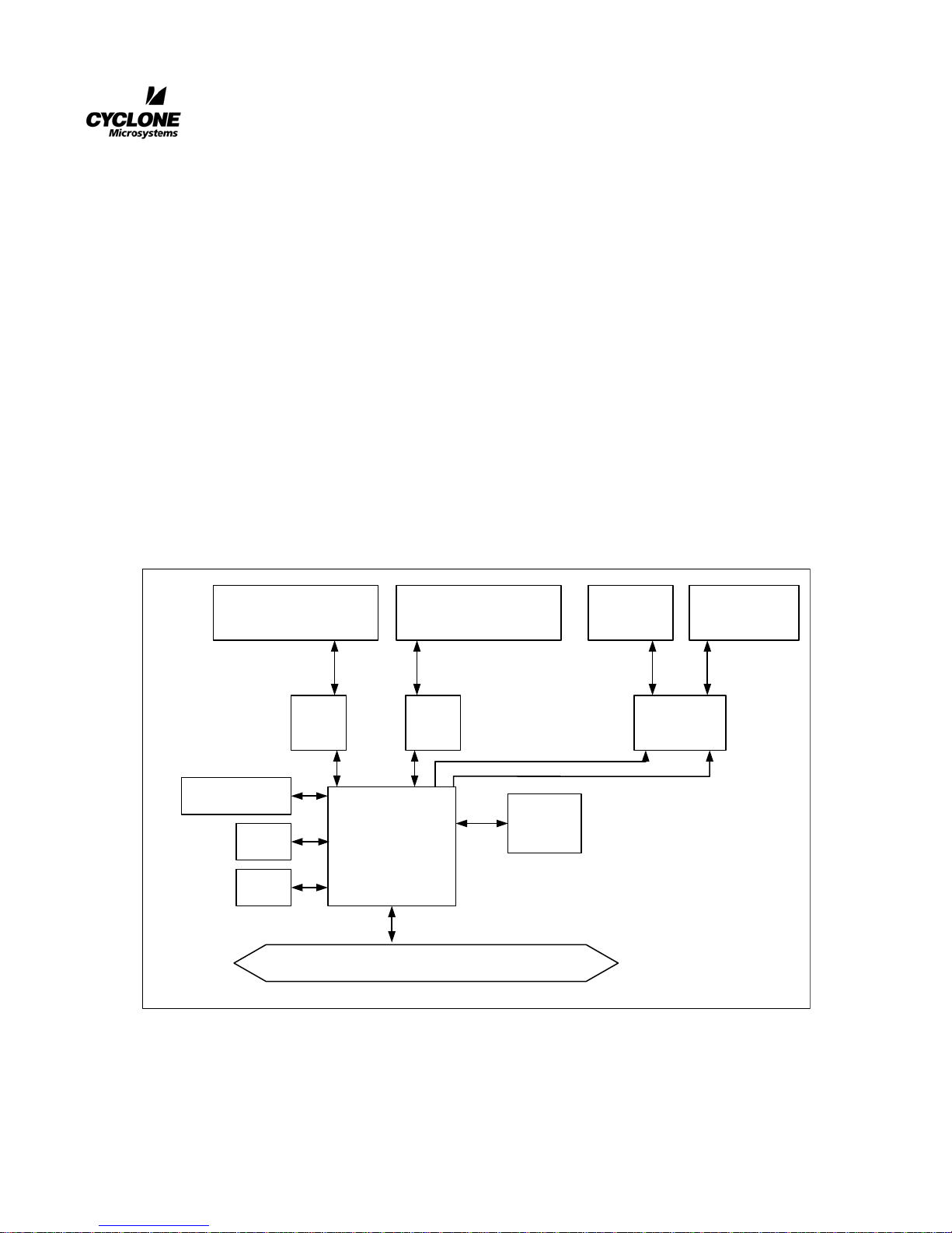
The CompactPCI-824 is a Hot Swap Intelligent I/O Controller.
The CPCI-824 card is based on the AMCC™ PowerPC™ 440GX, which is AMCC’s next generation
integrated processor based on the PowerPCI 440 core operating at a frequency of 667 MHz. The 440GX
supplies memory controller functions with up to 512 Mbytes of DDR SDRAM (64-bit with ECC) on an
SoDIMM module at 333 MHz DDR. The PowerPC core with 256K L2 cache, the memory controller,
the PCI-X Bridge, and the DMA controller of AMCC 440GX are among the features on the Processor
local bus operating at 128-bit and a frequency of 166 MHz. The 440GX Peripheral Bus (EPC) has three
devices; 8 Mbytes of Flash ROM, software LEDs, and external revision control registers. Additionally,
the 440GX contains four Ethernet MACs. Four Ethernet ports are provided on the CPCI-824. Two are
10/100/1Gb ports configured as RGMII and two are 10/100 Mbps ports and reconfigured as SMII. The
CPCI-824 also utilized one of the I2C bus interface units, and one of the two UART units. A block
diagram of the CPCI-824 is shown on Figure 1-1.
CHAPTER 1
GENERAL INTRODUCTION
Figure 1-1. CPCI-824 Block Diagram
DDR SDRAM
333 MHz
Flash
ROM
JTAG
10/100/1000
Ethernet Port
PHY PHY PHY
I/F
AMCC PPC440GX
MHz
Local Bus PCI-X
10/100/1000
Ethernet Port
Console
Serial
Port
10/100
Ethernet
Port
10/100
Ethernet Port
CPCI-824 User’s Manual 1-1
Revision 1.0, January 2006

GENERAL INTRODUCTION
1.2 FEATURES
•PowerPC™ Processor An AMCC 440GX embedded processor based on the AMCC
PowerPC superscalar core. It operates at a maximum frequency of
667 MHz internally.
• SD RAM Up to 512 MByte of 333 MHz DDR SDRAM is supported via a 200
pin SoDIMM module.
• Flash ROM 8 Mbytes of in-circuit sector-programmable Flash ROM provides
non-volatile storage on the CPCI-824. One 128 Kbyte sector of the
Flash ROM is reserved for the storage of non-volatile boot and
system parameters. System calls for storing parameters in this
memory are included in the Breeze Development Environmentª
• Con sole Serial Port An asynchronous serial port based on a 16C750 UART with an RS232 interface is provided for a console terminal or workstation
connection.
• Ethernet Ports Two 10/100/1Gb Base-TX Ethernet ports are provided. Each port
supports up to 1Gbps and uses a RJ45 style modular phone jack. The
MAC contained within the 440GX interfaces with 2 Broadcom
BMC5461S PHY transceivers.
Two 10/100 Base-TX Ethernet ports. Each supports u p to 1 00 Mbps
and also uses a RJ45 style modular phone jack. In this case the MAC
contained within the 440GX interfaces with a Broadcom BCM5248.
The BCM5248 is an eight port PHY, but we are only using the first 2
ports.
• Temperature Sensors Two LM75 type programmable temperature sensors with interrupt
signaling capability are provided for system monitoring purposes.
•I
O Messaging The CPCI-824 supports the I2O specification for interprocessor
2
communication.
• DMA Controller The 440GX supports 4 separate DMA channels for high throu ghput
data transfers between PCI bus agents and the local SDRAM
memory.
• Breeze Development
Environment™
Flash-resident ROM monitor / firmware package which supports
board-level initialization and application software development.
More information on the Breeze Development Environment™ can
be found in Breeze Developer’s Manual.
• Blade Style Interface The CPCI-824 receives power, fan detect, power supply status and
geographic addressing from J1 and J2. Note that the fan detect and
power supply status signals are only available when a CPCI-824 is
installed in the system slot.
• Hot Swap The CPCI-824 is a Basic Hot Swap board, compliant with PICMG
2.1.
1-2
CPCI-824 User’s Manual
Revision 1.0, January 2006
1.3 SPECIFICATIONS
GENERAL INTRODUCTION
Physical Characteristics The CPCI-824 is a single slo t, double high CompactPCI
™
card with a
peripheral slot interface. This product is equipped with an AMCC
PowerPC 440GX mcroprocessor.
Height 9.187” (233.35mm)
Double Eurocard (6U)
Depth 6.299” (160mm)
Width .8” (20.32mm)
Power Requirements The CPCI-824 requires +5V, +12V, -12V and +3.3V from the
CompactPCI
™
backplane J1 connector. The card is Universal and
support either +3.3V or +5V V(I/O).
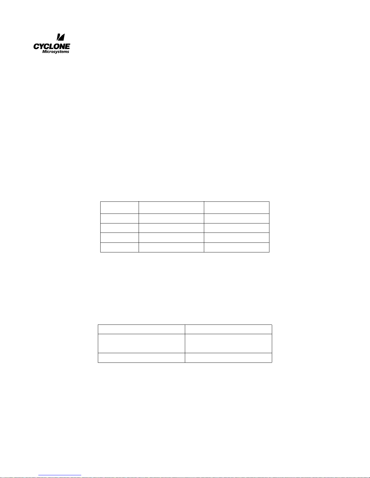
Table 1-1. CPCI-824 Power Requirements
Voltage Current Typical Current Maximum
+3.3V 3.49 Amps 4.99 Amps
+5V 0.03 Amps 0.04 Amps
+12V 0.01 Amps 0.02 Amps
-12V 0.02 Amps 0.03 Amps
1.4 ENVIRONMENTAL
A small amount of airflow will be required, such as is found in a typical Eurocard enclosure.
Operating Temperatures 0 to 55 Degrees Celsius
Relative Humidity
(non-condensing)
Storage Temperatures -55 to 125 Degrees Celsius
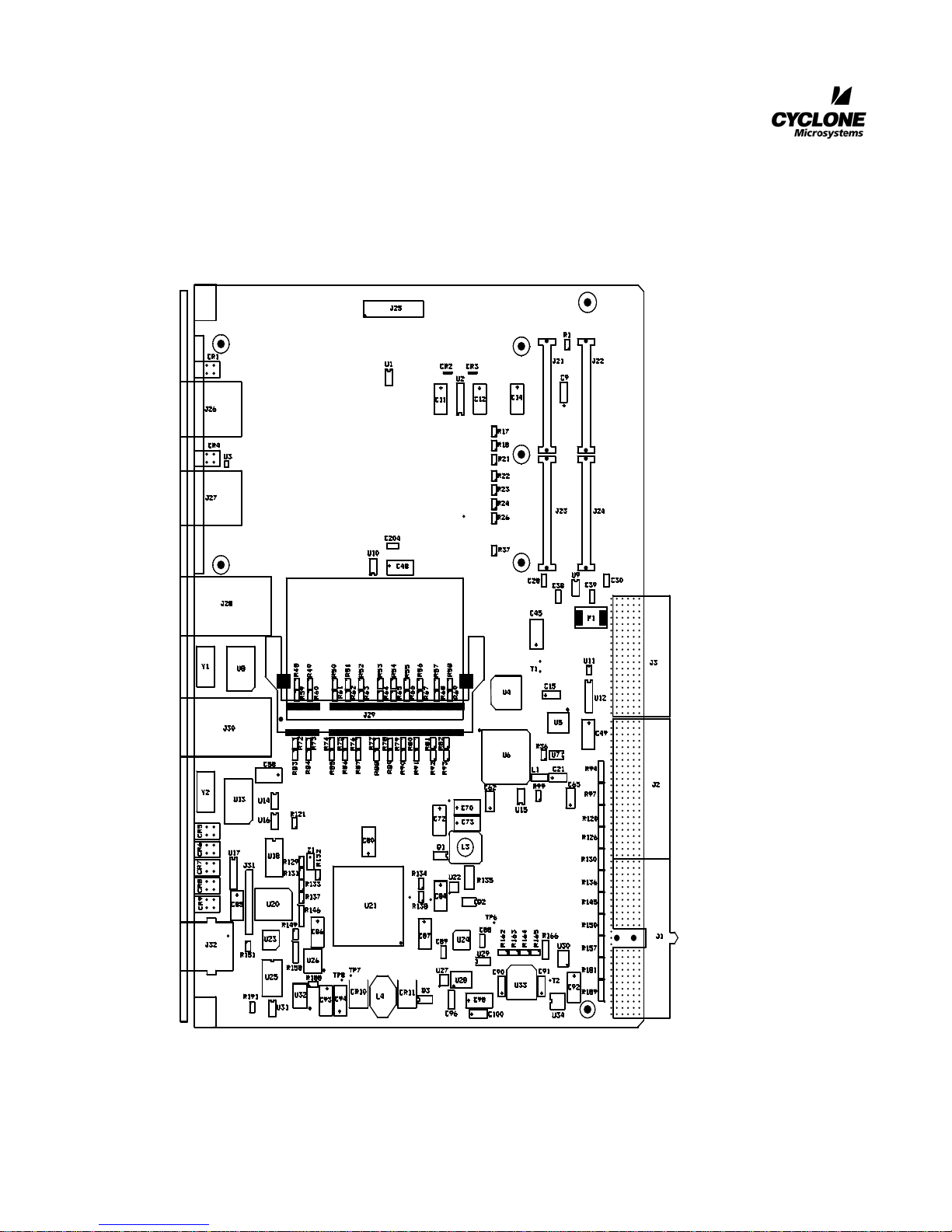
Figure 1-2 is a physical diagram (not to scale) of the CPCI-824 adapter, showing the location
designators of jumpers, connectors, and major ICs. Refer to this figure when component locations are
referenced in the manual text.
CPCI-824 User’s Manual 1-3
Revision 1.0, January 2006
Table 1-2. Environmental Specifications
0-95%
GENERAL INTRODUCTION
Figure 1-2. CPCI-824 Physical Configuration
1-4
CPCI-824 User’s Manual
Revision 1.0, January 2006

1.5 REFERENCE MANUALS
PowerPC 440GX Processor
User’s Manual, Document#
Data Sheet, Document #
GENERAL INTRODUCTION
Applied Micro Circuits Corporation
6290 Sequence Drive
San Diego, CA 92121
(800) 755-2622
http://www.amcc.com
RC28F640J3 Strata Flash Data Sheet
Developer’s Manual, Document #278848
Data Sheet, Document #278821
Intel Corporation
Literature Sales
P.O. Box 7641
16215 Alton Parkway
Irvine, CA 92619-7013
http://www.broadcom.com
LM75 Digital Temperature Sensor National Semiconductor
2900 Semiconductor Drive
P.O. Box 58090
Santa Clara, CA 95052-8090
(800) 272-9959
http://www.national.com
CompactPCI
3.0
™
Specification PICMG 2.0R
PCI Industrial Computers Manufacturing Group
401 Edgewater Place, Suite 500
Wakefield, MA 01880
(781) 224-1100
(781) 224-1239 Fax
www.picmg.org
PCI Local Bus Specification, Revision 2.2
PCI special Interest Group
5440 SW Westgate Dr. Suite #217
PCI-X Addendum Rev 1.0
Portland, OR 97221
(800) 433-5177 (U.S.)
(503) 222-6190 (International)
(503)222-6190 (Fax)
administration@PCISIG.com
Breeze for XScale 80331 Developer’s
Manual
2
I
0 Specification, Revision 1.0 I20 Special Interest Group
CPCI-824 User’s Manual 1-5
Revision 1.0, January 2006
Part Number 850-0151
Cyclone Microsystems Inc.
370 James Street
New Haven, CT 06513
(203) 786-5536
http://www.cyclone.com
(415) 750-8352
http://www.i2osig.org
 Loading...