

CyClone 600-2705 User Manual
600-2705 PCI Express Expansion System User’s Manual
Revision 1.0 February 2008
Cyclone P/N 800-2705
The information in this document has been carefully checked and is believed to be entirely reliable. However, no
responsibility is assumed for inaccuracies. Furthermore, Cyclone Microsystems, Inc. reserves the right to make
changes to any products herein to improve reliability, function, or design. Cyclone Microsystems, Inc. neither
assumes any liability arising out of the application or use of any product or circuit described herein, nor does it
convey any license under its right or the rights of others.
Copyright 2008 by Cyclone Microsystems, Inc.

CONTENTS
CHAPTER 1
1.1 INTRODUCTION..............................................................................................................................1-1
1.2 SPECIFICATIONS............................................................................................................................1-3
1.3 STANDARDS ...................................................................................................................................1-3
CHAPTER 2
2.1 THEORY OF OPERATION ..............................................................................................................2-1
CHAPTER 3
3.1 600-2705 CHASSIS..........................................................................................................................3-1
3.2 POWER CONSIDERATIONS...........................................................................................................3-1
CHAPTER 4
4.1 SYSTEM POWER UP......................................................................................................................4-1
4.2 SEATING OF CARDS......................................................................................................................4-1
4.3 LINK INDICATION - LED DEFINITION PCIe-409............................................................................4-1
4.3.1 Down-Shifting the PCIe-409................................................................................................4-1
4.3.2 De-Emphasis.......................................................................................................................4-2
4.4 LINK INDICATION - LED DEFINITION PCIE-414............................................................................4-2
CHAPTER 5
5.1 PHYSICAL CONFIGURATION.........................................................................................................5-1
CHAPTER 6
6.1 REFERENCE MANUALS.................................................................................................................6-1
i
600-2705 PCI Express Expansion System User’s Manual
Revision 1.0, February 2008

CONTENTS
LIST OF FIGURES
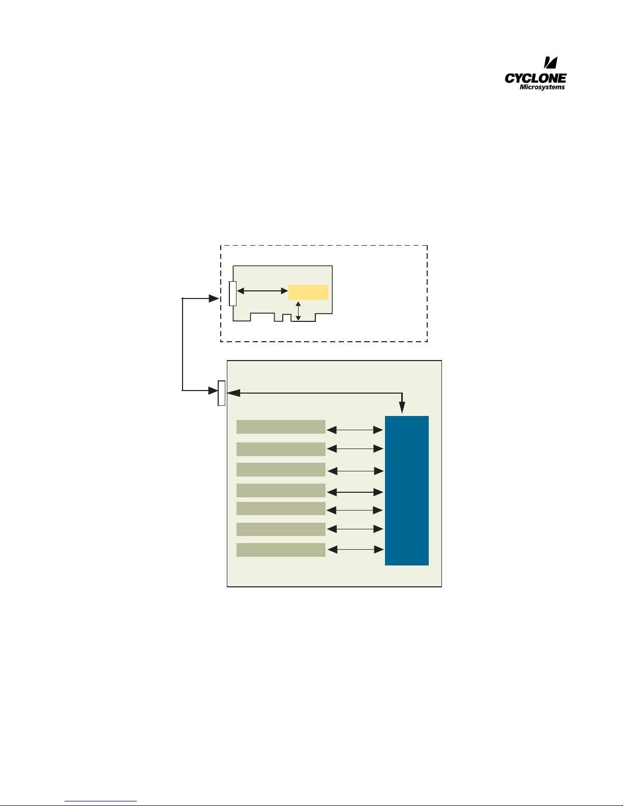
Figure 1-1. 600-2705 Block Diagram.....................................................................................................1-1
Figure 5-1. PCIe-414 Physical Configuration.........................................................................................5-1
Figure 5-2 PCIe-409 Front Panel..........................................................................................................5-2
Figure 5-3 600-2705 Chassis Drawing .................................................................................................5-2
Figure 5-4 600-2705 Chassis................................................................................................................5-3
LIST OF TABLES
Table 1-1. Specifications ... ... ... .... ... ... ... .... ... .......................................... ... ... .........................................1-3
Table 3-1. PCIe-414 Power Requirements.. ... ... ...................................................................................3-1
Table 3-2 PCIe-409 Power Requirements...........................................................................................3-1
Table 3-3 Power Supplied Per PCIe Slot.............................................................................................3-1
ii
600-2705 PCI Express Expansion System User’s Manual
Revision 1.0, February 2008

1.1 INTRODUCTION
The Cyclone Microsystems’ 2705 PCI Express Expansion System is a PCI Express (PCIe) Expansion
System that allows the user to add up to seven PCI Express add-in cards. Most PCs contain few PCI
Express slots making them poorly suited for embedded systems requiring a wealth of different I/O
boards and co-processor resources.
The 2705 PCI Express Expansion Systems permits system developers to use powerful and costeffective PCs as a foundation for a robust embedded system. The seven PCI Express slots are organized
as three x8 slots and four x4 slots. All expansion slots accommodate full length and full height cards and
are cooled by one 120 CFM and two 59 CFM fans. A 650 watt supply powers the rack mounted
expansion chassis.
The Expansion System supports 20 Gb/s bi-directional traffic to and from the host system and utilizes
non-blocking PCI Express switches for excellent peer-to-peer I/O bandwidth. For PCs with modern
BIOSs, the 2705 Expansion System is recognized by the host system upon boot-up, requires no
hardware specific drivers, and is entirely host operating system agnostic.
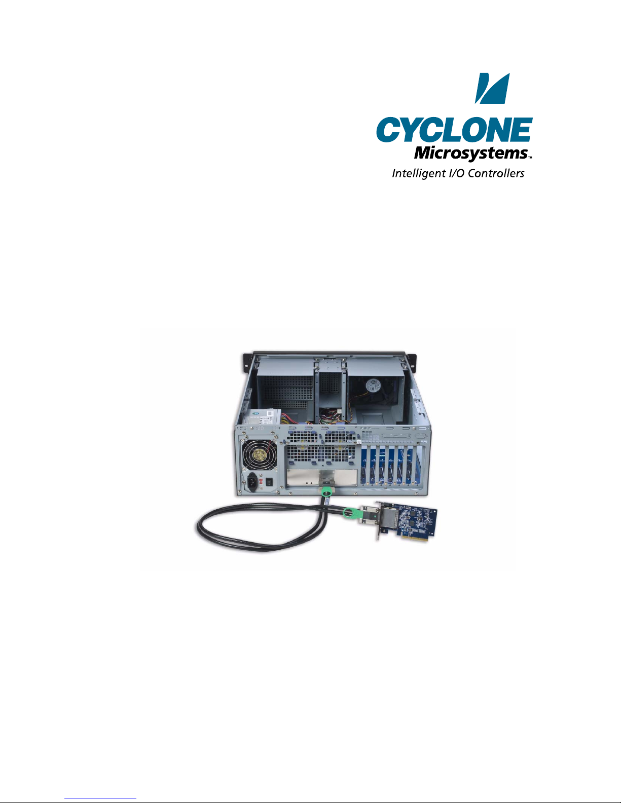
The 600-2705 system is composed from three elements: a PCI Express Host Bu s Cable Adapter, an
Expansion System Cable and an Expansion Chassis. Our PCIe-409 Host Bus Cable Adapter is inserted
into a host computer’s x8 PCIe slot. PCIe expansion cable links the PCI host with the expansion chassis.
The expansion chassis is populated with the PCIe-414 Switched Backplane.
CHAPTER 1
INTRODUCTION
PCI Express is a high performance, g eneral purpose I/O inter-connect defined for a wide variety of
computing and communication platforms. Key PCI attributes, such as its usage model, load-store architecture, and software interfaces are maintained, whereas its parallel bus implementation is replaced by a
serial interface. PCI Express take advantage of recent advances in point-to-point inter-connects, switchbased technology, and packetized protocol to deliver new levels of performance.
600-2705 PCI Express Expansion System User’s Manual 1-1
Revision 1.0, February 2008
INTRODUCTION
PCIe-409
PCI-E 401
x8
PCI-to-PCI
Bridge Link
REPEATER
Host PCI Express
System
64-bit CompactPCI Bus
x8 PCI ExpressCable
PCIe-414 Expansion System
PCI-Express x8 Cable Interface
PCI-Express x8 Slot
PCI-Express x8 Slot
PCI-Express x8 Slot
PCI-Express x8 Slot
PCI-Express x8 Slot
PCI-Express x8 Slot
PCI-Express x8 Slot
PCI-Express x8
x8
x8
x8
x4
x4
x4
x4
PCI-Express
Switch
1-2
Figure 1-1. 600-2705 Block Diagram
600-2705 PCI Express Expansion System User’s Manual
Revision 1.0, February 2008
 Loading...