

Page 1
Cyclone360
Wirless Controled LED Effect Lighting Fixture
User’s Manual
Page 2
Introduction
The Cyclone360 is a unique wireless controlled LED fi xture with a 360 degree beam. A
microprocessor controls the 16 million available colors of each of the 8 individual clusters.
Built in special effects are all controlled by the user using a wireless transmitter from 400
feet away. Communication is RF (radio frequency) so line of sight is not required.
The Cyclone360 has two modes of operation. Single Mode and Octal Mode. Single Mode the
Cyclone360 operates as a conventional ColorMaker fi xture with all 8 clusters controlled using
a single RGB channel. Single mode also includes our ColorRoll technology. Octal Mode the
Cyclone360 requires 10 RGB channels to control the clusters and effects. 8 channels are requires
to set the individual RGB levels of each of the clusters and 2 channels for effects. The Cyclone360
incorperates our auto address feature to easy setup. The Cyclone360 is compatable with all
ColorMaker transmitters operating on 916 Mhz.
The Cyclone360 was designed for a variety of applications from high energy effects fi xture to soft
glow illuminator. Mounting bracket provides the user with the option of operating the Cyclone360
as a horazontal or vertical fi xture for cool effects. ColorMaker Inc. also offers brackets to hang the
fi xture inside spandex columns, cones or balloons.
The Cyclone operates on 12 volts DC and can be powered by one of our Battery packs or run from
an AC 110 volt outlet using the Gl2500 power supply.
Table of Contents
Cyclone360 Overview 1
Auto Addressing 1
Effects Controls 3
Fade or Flash 4
Patterns 5
Scene Control CM-T10-PRO-Enhanced 5
1
Page 3

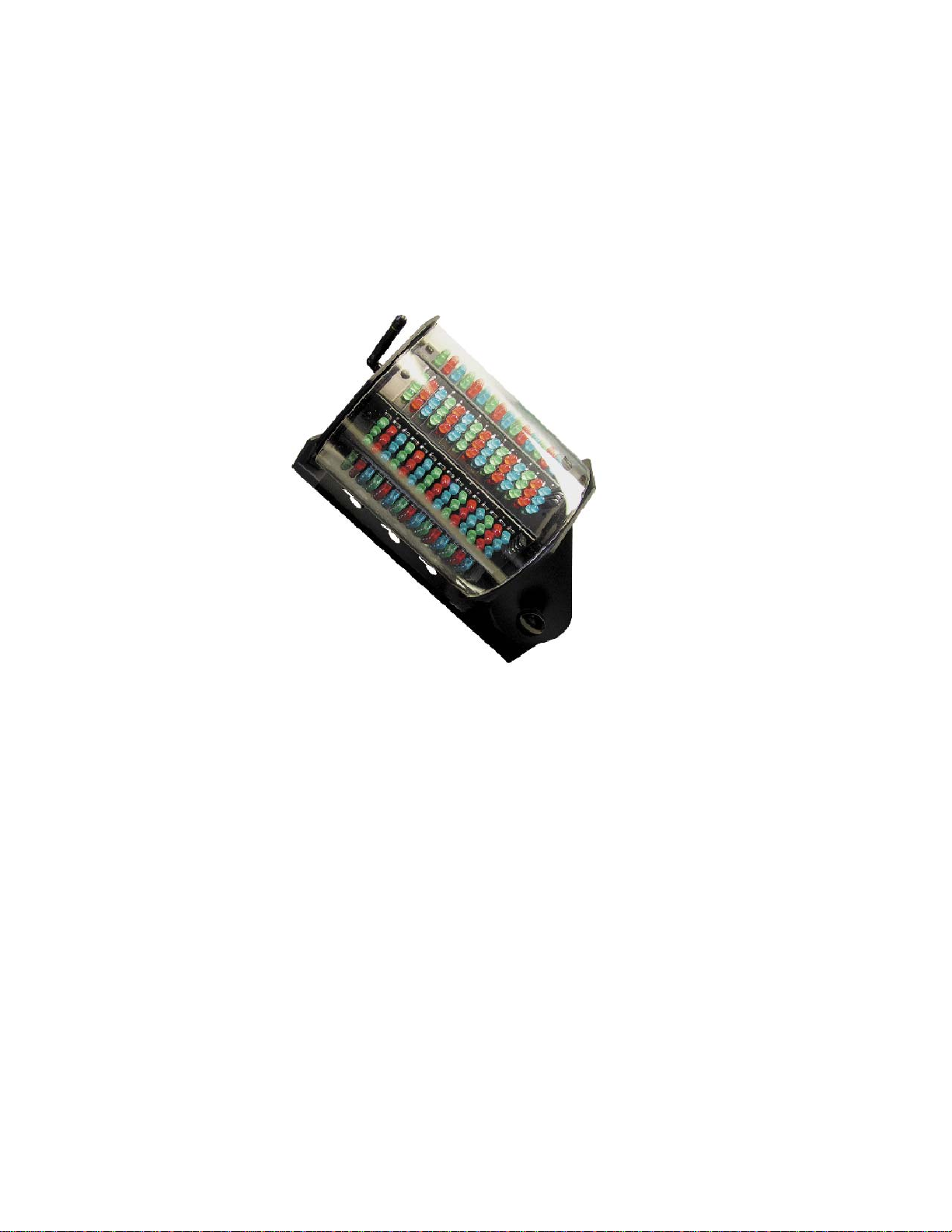
Cyclone360 Overview
This maunal covers both Cyclone360-8 and
Cyclone360-5. All fi xture operating functions are
identical.
A: Antenna, receives the RF data. Keep all
metal objects at least 3 inches away for best
performance.
B: Tilt Adjustment Knob, secures fi xture tilt
position from 0 to 90 degreens
C: Mounting Base, Keyed base to mount fi xture
to battery pack or fi xture stand.
D: Status Indicator, identifi es fi xture operating
mode.
E: Program button, enables program to auto
addressing fi xture.
F: Power input Jack, 12 volt power input.
G: Mode selector switch, sets fi xture mode 1
(single) or mode 8 (octal).
Getting Started
The following instructions are explained using the CM-T10-PRO-Enhance remote. Later in this manual CMI-1600
DMX interface will be covered and how to use mutliple Cyclone360 on seperate adresses. This manual will cover
Octal (8) Mode in detail with examples on how to use the effects.
Power up the Cyclone360
To apply power to the Cyclone360 use one of ColorMaker battery packs or GL2500 110 volt supply.
Selecting the Mode
The Mode selector switch (G fi gure 1) sets the fi xture to the operating mode desired. 1 (Single) mode the fi xture will
operate as a conventional ColorMaker fi xture with all 8 clusters operating using a single RGB channel. 8 (octal) mode
the fi xture will be controlled using 10 RGB channles 8 channels for the clusters and 2 additional channels for the
effects.
Auto Addr essing
The Cyclone360 has an auto address feature. This feature automatically set the fi xture to a desired button on the
transmitter. When the Fixture is operating in Octal mode then all 10 channel on the remote will be used for a single
Cyclone360 so be sure to set the Netork address on the CM-T10-PRO-Enhanced before programming fi xture address.
To set the address press and hold the Program button on the Cyclone360 until the indicator light turns yellow then
release the button and using the CM-T10-PRO-Enhanced remote press Red UP button on the remote. The indicator
will turn green identifying the fi xture has received the new address.
FIGURE 1
ColorRoll
ColorRoll is
2
Page 4
Controls
The following instructions are for Octal Mode only
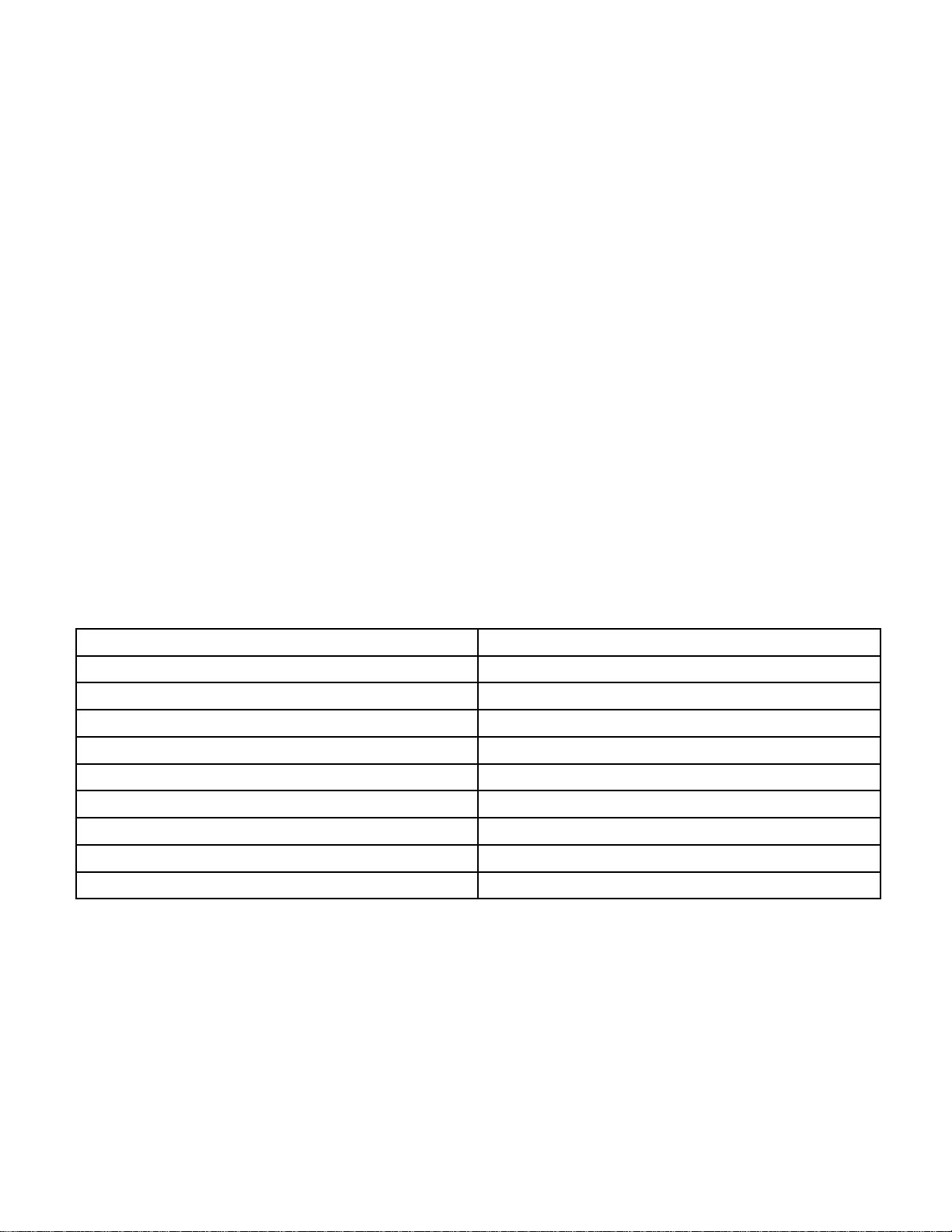
Table below list the function of each channel and the functions of the RED, GREEN and BLUE
dimmer buttons.
Q Select RED UP/DN GREEN UP/DN BLUE UP/DN
Q1 Cluster 1 RED Cluster 1 GREEN Cluster 1 BLUE
Q2 Cluster 2 RED Cluster 2 GREEN Cluster 2 BLUE
Q3 Cluster 3 RED Cluster 3 GREEN Cluster 3 BLUE
Q4 Cluster 4 RED Cluster 4 GREEN Cluster 4 BLUE
Q5 Cluster 5 RED Cluster 5 GREEN Cluster 5 BLUE
Q6 Cluster 6 RED Cluster 6 GREEN Cluster 6 BLUE
Q7 Cluster 7 RED Cluster 7 GREEN Cluster 7 BLUE
Q8 Cluster 8 RED Cluster 8 GREEN Cluster 8 BLUE
Q9 Fade Time Follow Time Reserved for future use
Q10 Fade or Flash Pattern Pattern Direction
Effects Defi nitions
Fade Time: The Time the scene takes to fade from scene to scene.
Follow Time: The time between scenes.
Fade or Flash: Sets the Cyclone to fade or fl ash.
Pattren: Sets one of 8 preset patterns.
Pattern Direction: Sets the pattern direction (Foward or Reverse)
Effects
The Cyclone360 effects are controlled using 2 channel buttons and the RGB setting of each channel. Each of the
effects have a value from 0 to 100 as displayed on the CM-T10-PRO-Enhanced display. We will cover each of the
effects and the how the value will affect the Cyclone360. For any effects to appear we must fi rst set the 8 clusters. For
this example we will set clusters 1 through 7 to RED and Cluster 8 to BLUE.
Step 1: Press Q1 and RED UP until the display read 100. Cluster 1 on the Cyclone360 should be on.
Step 2: Repeat step 1 for Q2 through Q7.
Step 3: Press Q8 and press BLUE UP until display read 100.
The Cyclone360 should now have 1 BLUE cluster and the other 7 should be RED.
To activate the effects the Fade Time (Q10 RED) must be greater than 0.
Note: Fade time values are reversed from our ColorRoll Technology. 0 is OFF, 1 is Slow and 100 is Fast.
Activate the effects by pressing the RED UP button. For this example we will set it to 100 so press the RED UP button
until the display reads 100 then do the same for the Follow Time by pressing GREEN UP until the display reads 100.
The Cyclone360 should now be RED with a GREEN Cluster circling.
Continue.....
3
Page 5

Below are two charts for the Fade Time and Follow Time values.
Fade Time V alue chart
Value Function Calculated Time
0 OFF Fade Time OFF - Effects Disabled
1-50 Low Speed rate Full Color fade time 3 minutes - 1 minute
51-100 High Speed Rate Full Color fade time 1 minutes - 3 seconds
Follow Time Chart
Value Function Calculated Time
0-50 Follow Time Long Follow Time 1 minute- 30 seconds
51-99 Follow Time Short Follow Time 30 seconds - 1 second
100 OFF Follow Time OFF
Play with the RED (Fade Time) and GREEN (Folow Time) dimmer values and see how they affect the speed of the
of the circling GREEN Cluster. The disable the effects set the RED (Fade Time) to 0.
The Cyclone360 Q9 BLUE channel 9 is not used and reserved for future use.
Fade or Flash (Q10 RED)
The Cyclone360 can be set to fade or fl ash by adjusting Q10 RED dimmer. This is an easy adjustment dimmer levels
0 to 49 set the Cyclone360 to Fade setting the dimmer from 50 to 100 disables the Fade and set the Cyclone360 to
fl ash through the selected colors. When Flash is enabled the Follow Time value is disabled.
Try it. Your Cyclone360 should still be circling a GREEN cluster. Press Q10 and Press the RED UP button until the
display reads 100 or any value above 49. Wow thats fast.... Press Q9 then press RED DN button to slow the speed
of the Cyclone360. Play with the Fade Time (Q9 RED) value and see how it affects the speed of the circling GREEN
cluster.
Pattern Direction (Foward or Reverse)
Here is a another easy one. Q10 BLUE will adjust the direction of the pattern Foward or Reverse. 0 to 49 sets the
direction to Foward and 50 to 100 set the direction to Reverse. Go ahead and just give it a whirl.... no pun intended.
Pattern (Q10 GREEN)
This adjustment set the Cyclone360 to run 1 of 5 preset patterns. All the example effects we have been reviewing
have been pattern 1 which is a simple circular pattern. Pattern 2 through 5 are a collection of patterns when used with
multiple colored clusters along with fade time and follow time values will create some cool effects. Pattern table list
the pattern and the dimmer level for each pattern
Pattern Number Dimmer Level
1 0 to 20
2 21-40
3 41-60
4 61-80
5 81-100
4
Page 6

Patterns
When patterns are activated all 8 clutsers sequence to the selected pattern. Each pattern has 8 steps which
continuously loop until the pattern in changed or the effects are disabled. Below is a diagram of all 5 patterns and the
chase sequence each will use. The Q10 (BLUE) Foward or Reverse effects with change the sequence direction.
Pattern 1
Editing Cluster Colors
LED cluster colors can be changed
while a pattern is running. The
sequence of the cluster are shifted as
the pattern shifts through all 8 steps of
the pattern so cluster controlled by Q1
at startup may not be the same cluster
after a pattern has been activated.
When the Cyclone360 effects are
disabled by bringing FadeTime value
to 0 the cluster sequence will not be
reset until a Blackout command is
received from the remote. This will probably never be an issue but I though I should mention it any way.
Pattern 2 Pattern 3
Pattern 4
Pattern 5
This concluedes the lesson on Cyclone Effects.
Using the Scene Control on the CM-T10-PRO-Enhanced
The CM-T10-PRO-Enhanced can control up to 9 Cyclone360 fi xtures. This will require the use of all 9 network
addresses. Using the Scene record and play funtions on the CM-T10-PRO-E the Cyclone colors and effects can be
recorded for easy playback. Its recomended to set the CM-T10-PRO-E Fade control to OFF (Shift + ColorROll 1)
when playing back a Cyclone360 setting.
Single Mode (1)
The Following lesson will cover the ColorRoll feature. For this lesson you will need to switch the Cyclone360 to
Single (1) mode and enable the ColorRoll option. The indicator light should be red. If not press and release the
program button to switch the ColorRoll ON.
5
Page 7

Introducing
ColorRoll™ Technology by ColorMaker Inc.
What is ColorRoll ?
ColorRoll is a technology developed by ColorMaker Inc. to operate on the ColorMaker line of wireless
LED fi xtures. When activated a colletion of colors are transmitted to the fi xture by a remote. Once the
fi xture receives the packet of data which takes less that 1 second the fi xture will start rolling throught
the colors fading from one color to the next with fl icker free transition. This is an endless loop when the
last color is reached the process starts over to the fi rst color. Once the ColorRoll has started the Fade
Time from color to color can be controled from 15 seconds to 5 minutes for each color. The fi xture will
operate completely independant of the transmitter until it receives a singal to terminate. Custom colors are
programmed and saved in the remote. There are 3 buttons marked ColorRoll 1, ColorRoll 2 and ColorRoll
3 witch are used for the ColorRoll featture.
How many Colors are there?
If we do the math there are 16 million colors. there are 255 levels for each color with 3 Colors. which totals
255 X 255 X 255 = 16,000,000
Where do I get the colors for a ColorRoll ?
Creating a ColorRoll is the same as creating a scene with a few minor adjustments. When a scene is
created using all 10 fi xtures Q1 through Q10 this represents the 10 colors in a ColorRoll. The color setting
for Q1 will be the fi rst color in the ColorRoll and Q10 will be the last color in the ColorRoll. If you dont have
10 fi xtures then you can use the digital display to set the RGB values. The remote does not know if you
are using fi xtures.
How to create a ColorRoll using 10 colors
1) The fi rst step is to chose the fi rst color in the ColorRoll by selecting Q1 and then set the color. Do this
through Q10.
2) With all 10 colors set press and release the REC key in the yellow Scene Control box. The display will
read REC.
3) Now select where you want to store the ColorRoll pattern. Your options are ColorRoll 1, ColorRoll 2 or
ColorRoll 3.
4) once you have made your selection the display will return to the last selected fi xutre and the ColorRoll
has been saved.
And you thought is was going to be diffi cult! Well were not done yet.
Lets do a ColorRoll with only 3 colors, Red, Green and Blue.
1) The fi rst step is to chose the fi rst color in the ColorRoll by selecting Q1 and then set the color. Do this
through Q3 since we only want 3 colors.
This is the confusing part so stay focused.
The ColorRoll knows you have 3 colors Red, Green and Blue. But it does not know wheather you intended
the 4th color which if OFF to be part of the ColorRoll pattern. Well its been programmed to assume Yes
its part of the pattern. So now your ColorRoll looks like Red, Green, Blue and OFF. So if you played this
ColorRoll pattern back it will look like a dead spot in your program.
Stay Focused …
6
Page 8

How do I remove the dead spot in my ColorRoll ?
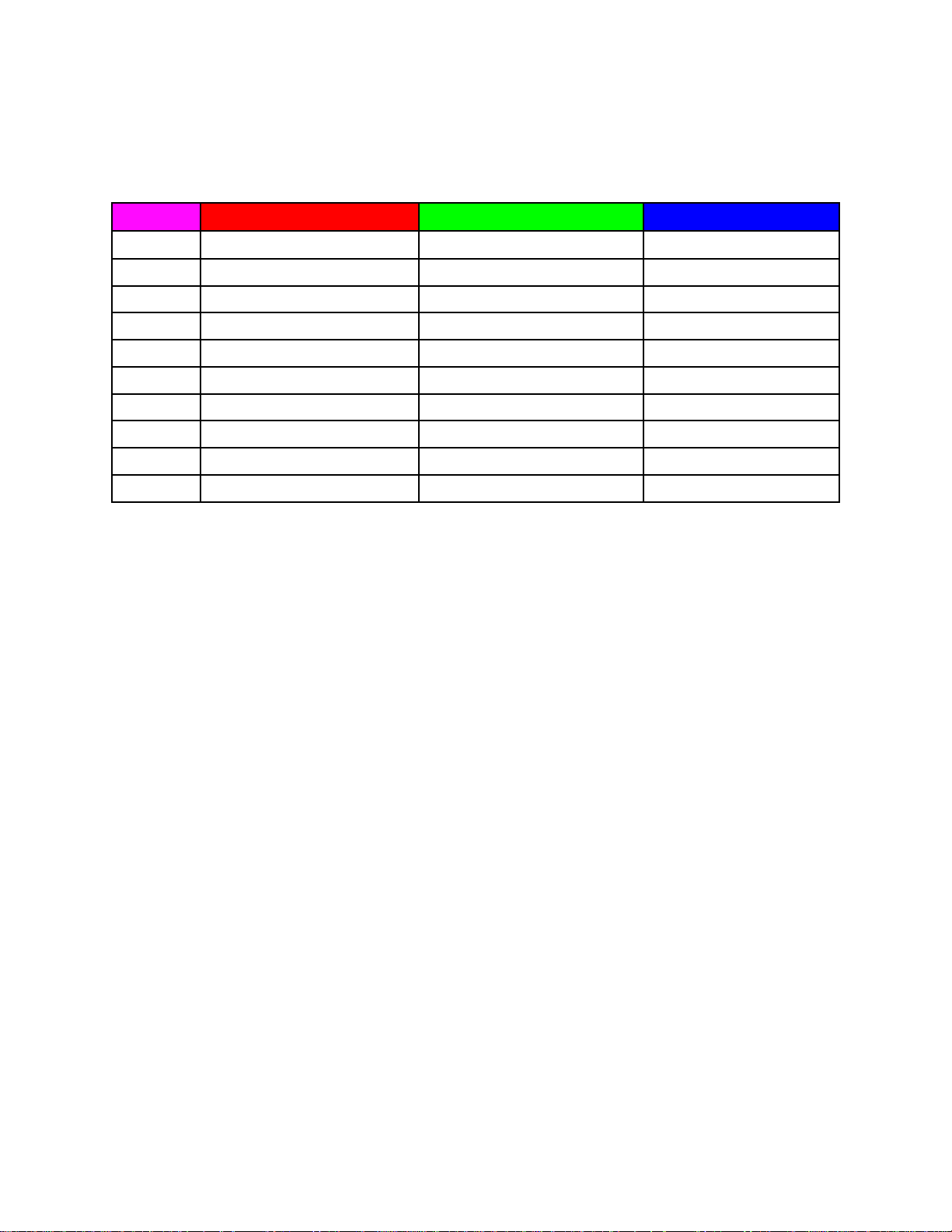
We need to tell the remote that the 4th color which is OFF is not part of the pattern. The way we do this is to make the
colors not in the pattern the same as the last color in the pattern. The last color in the pattern is Blue so we would set
Q4 to blue, Q5 to blue, Q6 through Q10 to Blue. Now when the ColorRoll runs it will see Red, Green then Blue when
it gets to the 4th color its still blue so it checks colors 5,6,7,8,9 and 10. Until a new color is used the ColorRoll will
not change so our results will be Red, Green and Blue then repeats.
Example 1: ColorRoll setting that starts with Red then fades through all 10 colors then repeats.
Fixtures
Q1 Q2 Q3 Q4 Q5 Q6 Q7 Q8 Q9 Q10
Example 2: ColorRoll process that starts with Red the fades to Green then fades to Blue then repeats.
Fixtures
Q1 Q2 Q3 Q4 Q5 Q6 Q7 Q8 Q9 Q10
If you can master the ColorRoll programming then its all down hill from here.
Starting a ColorRoll
Starting a ColorRoll is done a little diffrent that starting a scene. With ColorRoll the Play button is not use just select a fi xture Q1 through Q10 then select a ColorRoll pattern ColorRoll button 1, 2 or 3. If a ColorRoll program was
recorded then it will start. Select another fi xture and then another ColorRoll or use the same ColorRoll. Shift + Q10
works well with ColorRoll to send a Patterns to all fi xtures with one button.
Since the ColorRoll is running independant of the remote some fi xtures may roll slightly faster which after time
will cause them to roll unevenly. Choose from one of our other ColorMaker line of transmiters with continious
signal control if tracking is needed.
Controling the ColorRoll
The ColorRoll patterns can be controlled on how fast the colors fade and weather they fade or Flash. Fade rates can be
set from 3 seconds to 5 minutes.
*Remeber fade rates are perportional to dimmer values
ColorRoll fade rate keys are shared with the Red and Green UP and Down keys. Marked with Roll Rate. Rate keys are
only active after a ColorRoll patterns has been sent to the fi xture.
ColorRoll Fade Rate setting
There are two fade rate settings. Rate and Rate Multiplier. Fade rate keys are shared with the Red and Green UP and
Down keys. Marked with Roll Rate. Rate keys are only active after a ColorRoll patterns has been sent to the fi xture.
These two values are controlled by Red and Green UP and DN keys. The Red UP and DN keys controls the Rate
Value the Green UP and DN keys controls the Rate Value Multipler.
Continues to next Page
7
Page 9

Adjusting the ColorRoll Fade Rate
Example:
1) Start a ColorRoll by selecting a fi xture, Q1 will be fi ne.
2) Press a ColorRoll button which has been previously programmed.
3) After pressing a ColorRoll button the Red and Green UP and DN dimmer keys become Rate Keys.
4) Press the Red DN button and bring the Rate to 0 if not already inicated by the display. Do the same for Green.
The ColorRoll is now running at full speed roughly 3 seconds per color.
To increase the fade rate (make it fade slower) Press the Red UP key which will increase the fade. Bring it up to about
50%. There will be a noticable decrease in the roll rate. By increasing Rate Value Multiplier which is the Green UP
and DN keys it will make the fade rate even slower. It probably will not be noticable but over a period of 3 to 4 minutes you will notice a change.
Fade Rate Values Saved to Memory
Each of the ColorRoll buttons stores its own fade rate and fade rate multiplier values so fast and slow ColorRoll
patterns can be programmed. The rate values are saved each time they are changed. When a ColorRoll button is re
programmed the Fade Rate Value and the Fade Rate Mutiplier Value of the previous ColorRoll will be used until it is
changed.
Need a Disco Look ? ColorMaker can do it.
Along with Fade Rate there is also a control to make the LED fi xture FLASH through the ColorRoll pattern. After
a ColorRoll button is pressed the Blue UP and DN keys become Flash Control buttons. By bringing the Value above
50% it turns off the fade control and colors fl ash through the ColorRoll patterns. The fl ash rate can be controled by
Fade Rate and Fade Rate Multipier. Flash value is also stored when changed.
8
Page 10

9
Page 11

Warranty
ColorMaker Inc. hereby warrants, to the original purchaser,
ColorMaker Inc. products to be free of manufacturing defects in
materials and workmanship for a period of (90 days) from the
date of purchase. This warranty shall be valid only if product is
purchased within the United States of America. It is the owners
responsibility to establish the date and place of purchase by
accepting evidence, at the time service is sought.
For warranty service, send the product to the ColorMaker Inc.
factory. All shipping charges must be prepaid. Equipment must be
sent in its original package and to include all control devices.
Warrant is void if serial number has been altered or removed, seals
have been voided, if the product is modifi ed in any manner which
ColorMaker Inc. concludes, after inspection, affects the reliability of
the product; if the product has been repaired or services by anyone
other than ColorMaker Inc. unless prior written authorization was
issued to purchaser.
ColorMaker Inc. reserves the right to make any changes in the
designs and/or improvements upon its products without any
obligation to include these changes in any products theretofore
manufacture.
Factory location:
ColorMaker Inc.
980 Sunshine Lane Suite T
Altamonte Florida 32714
(407) 862-3363
ColorMaker™ is a Trade Mark
for ColorMaker Inc.
ColorMaker.net
 Loading...