

Page 1

Cyclades® P M I P DU
Installer/Administrator/User Guide
Page 2

FCC Warning Statement
The Cyclades PM IPDU has been tested and found to comply with the limits for Class A digital devices, pursuant to Part 15 of the FCC rules. These limits are designed to provide reasonable protection against harmful interference when the equipment is operated in a commercial environment. This equipment generates, uses, and
can radiate radio frequency energy and, if not installed and used in accordance with the Installation & Service
Manual, may cause harmful interference to radio communications. Operation of this equipment in a residential
area is likely to cause harmful interference in which case the user is required to correct the problem at his or
her own expense.
Canadian DOC Notice
The Cyclades PM IPDU does not exceed the Class A limits for radio noise emissions from digital apparatus set
out in the Radio Interference Regulations of the Canadian Department of Communications.
Le Cyclades PM n’émete pas de bruits radioélectriques dépassant les limites applicables aux appareils numériques de la classe A prescrites dans le règlement sur le brouillage radioélectrique edicté par le Ministère des
Communications du Canada.
Page 3

Cyclades® PM IPDU
Installer/Administrator/User Guide
Avocent, the Avocent logo, The Power of Being There and Cy clades are
registered trad emarks of Avocent Corporation. All other ma rks are the
property of th eir respective owners.
© 2006 Avocent Corporation. All rights reser ved. 590-667-501A
Page 4
Instructions
This symbol is intended to alert the user to the presence of important operating and maintenance
(servicing) instructions in the literature accompanying the appliance.
Dangerous Voltage
This symbol is intended to alert the user to the presence of uninsulated dangerous voltage within the
product’s enclosure that may be of suffici e nt magnitude to cons titute a risk of electric shock to persons.
Power On
This symbol indicates the principal on/off switch is in the on position.
Power Off
This symbol indicates the principal on/off switch is in the off position.
Protective Grounding Terminal
This symbol indicates a term in al which must be connected to earth ground prior to making any other
connections to the eq uipment.
Page 5

TABLE OF CONTENTS
Table of Contents
List of Figures ................................................................................................................ vii
List of Tables................................................................................................................... ix
Chapter 1: Introduction .................................... ...... ....... ...... ...... ....... ...... ....... ...... ....... ..... 1
Features and Benefits ........................................................................................................................1
Alarms and monitoring............................................................................................................... 1
Sequential power up...................................................................................................................1
Support for daisy chaining ................................. ...... ............................................. .....................2
Creation of user accounts...........................................................................................................2
Integration with Cyclades management products ......................................................................2
Hardware Configuration Options......................................................................................................2
Standalone configuration .............................. ............................................. ...... ..........................2
Daisy chained configuration.......................................................................................................3
Integrated configuration.............................................................................................................4
Accessing the System Console...........................................................................................................6
Direct console access ........................................................................... ...... ...... ..........................6
Console access through a management device ..........................................................................6
Component Overview.........................................................................................................................7
Cyclades PM8 IPDU..................................................................................................................7
Cyclades PM8i IPDU.................................................................................................................8
Cyclades PM10 IPDU................................................................................................................8
Cyclades PM10i IPDU...............................................................................................................9
Cyclades PM10i-L30A IPDU.....................................................................................................9
Cyclades PM10i-32A IPDU .......................................................................................................9
Cyclades PM10i-32Au IPDU ...................................................................................................10
Cyclades PM20 IPDU..............................................................................................................10
Cyclades PM20i IPDU.............................................................................................................10
Cyclades PM20i-32A IPDU .....................................................................................................11
Cyclades PM20i-32Au IPDU ...................................................................................................11
iii
Chapter 2: Installation ............................................................... ....... ...... ....... ...... ....... ... 13
Getting Started.......................................... ...... ............................................. ...... ...... ........................13
Page 6

iv Cyclades PM IPDU Installer/Administrator/User Guide
Supplied with the PM IPDU............................................................................................................13
Modular input power cables for the PM IPDU........................................................................14
Optional outlet cable package..................................................................................................16
Rack Mounting the Cyclades PM IPDU..........................................................................................16
Installation environment...........................................................................................................17
Daisy Chaining PM IPDUs .............................................................................................................19
Plugging Devices Into PM IPDU Outlets........................................................................................20
Powering Up the PM IPDU.............................................................................................................20
Making a Direct Connection for Console Access............................................................................20
Chapter 3: Configuration........................... ....... ...... ....... ...... ...... ....... ...... ....... ...... ....... ... 23
Default Configuration Parameters.............................................................. ....................................23
Initial Configuration Using the Command Prompt.........................................................................24
Resetting the Admin Password ........................................................................................................25
Upgrading the Cyclades PM IPDU Firmware................................................................................26
Chapter 4: Command Line Interface ............................................................................ 31
PM IPDU User Interface.................................................................................................................31
Daisy chained PM IPDUs in the login prompt.........................................................................31
Logging in to the PM IPDU......................................................................................................32
Commands .......................................................................................................................................32
adduser.............................................................................................................................................33
alarm................................................................................................................................................34
assign...............................................................................................................................................34
buzzer...............................................................................................................................................35
current..............................................................................................................................................35
currentprotection.............................................................................................................................36
currseg.............................................................................................................................................37
cycle .................................................................................................................................................38
dbsync .............................................................................................................................................. 39
deluser..............................................................................................................................................39
display..............................................................................................................................................40
exit....................................................................................................................................................41
factory_defaults ...............................................................................................................................41
help...................................................................................................................................................42
humidity ...........................................................................................................................................43
Page 7

Table of Contents v
hwocp...............................................................................................................................................44
id ......................................................................................................................................................45
interval.............................................................................................................................................46
list.....................................................................................................................................................47
lock...................................................................................................................................................48
name.................................................................................................................................................48
off .....................................................................................................................................................49
on .....................................................................................................................................................50
passwd..............................................................................................................................................50
reboot...............................................................................................................................................51
restore..............................................................................................................................................53
save ..................................................................................................................................................53
status................................................................................................................................................54
syslog ...............................................................................................................................................55
temperature......................................................................................................................................56
unassign...........................................................................................................................................57
unlock...............................................................................................................................................57
upgrade............................................................................................................................................58
ver ....................................................................................................................................................59
voltage..............................................................................................................................................60
whoami.............................................................................................................................................61
Appendices..................................................................................................................... 63
Appendix A: Specifications..............................................................................................................63
Appendix B: Safety Instructions.......................................................................................................73
Appendix C: Circuit Breakers.......................................................................................................... 79
Index................................................................................................................................ 85
Page 8

vi Cyclades PM IPDU Installer/Administrator/User Guide
Page 9

LIST OF FIGURES
List of Figures
Figure 1.1: Standalone Configuration...............................................................................................3
Figure 1.2: Daisy Chained Configuration.........................................................................................4
Figure 1.3: The Cyclades PM IPDU with a Cyclades Management Device.....................................5
Figure 1.4: Cyclades PM8 IPDU......................................................................................................7
Figure 1.5: Cyclades PM8i IPDU.....................................................................................................8
Figure 1.6: Cyclades PM10 IPDU....................................................................................................8
Figure 1.7: Back of the Cyclades PM10iIPDU.................................................................................9
Figure 1.8: Front of the Cyclades PM10iIPDU................................................................................9
Figure 1.9: The Cyclades PM20 IPDU...........................................................................................10
Figure 1.10: The Cyclades PM20i IPDU, PM20i-32A IPDU and PM20i-32AU IPDU.................11
Figure 2.1: Rack Mounting a Cyclades PM10 IPDU, PM10l IPDU and PM8iIPDU....................17
Figure 2.2: Rack Mounting Holes on the PM8i IPDU, PM10 IPDU and PM10i IPDU................18
Figure 2.3: PM10 IPDU with Mounting Brackets Installed ...........................................................18
Figure 2.4: Rack Mount for the Cyclades PM8i IPDU, PM10 IPDU or PM10i IPDU..................19
Figure 2.5: Connecting a Local Work Station to the Cyclades PM IPDU......................................21
Figure 3.1: Sending Firmware using HyperTerminal.....................................................................28
Figure 3.2: Sending Firmware using Minicom ...............................................................................29
Figure C.1: PM10-L30A IPDU Circuit Breakers ...........................................................................80
Figure C.2: PM10i-L30A IPDU Circuit Breakers..........................................................................80
Figure C.3: PM20-L30A IPDU Circuit Breakers ...........................................................................81
Figure C.4: PM20i-L30A IPDU, PM20i-32A IPDU and PM20i-32Au IPDU Circuit Breakers....82
vii
Page 10

viii Cyclades PM IPDU Installer/Administrator/User Guide
Page 11

LIST OF TABLES
List of Tables
Table 2.1: PM IPDU Shipping Box Contents, Part Numbers and Description...............................13
Table 2.2: PM8i-10A IPDU and PM10i-10A IPDU Power Cables................................................15
Table 2.3: PM10i-15A IPDU Power Cables ............................................... ....................................16
Table 2.4: PM10i-16A IPDU and PM 20i-16A IPDU Power Cables.............................................16
Table 2.5: PM10i-20A IPDU and PM 20i-20A IPDU Power Cables.............................................16
Table 2.6: PM IPDU Optimum Installation Environment...............................................................17
Table 4.1: User Commands.............................................................................................................32
Table 4.2: Admin User (privileged) Commands..............................................................................33
Table A.1: PM8-15A IPDU Specifications......................................................................................63
Table A.2: PM8-20A IPDU and PM8-L20A IPDU Specifications..................................................64
Table A.3: PM8i-10A IPDU Specifications.....................................................................................64
Table A.4: PM10-15A IPDU Specifications....................................................................................65
ix
Table A.5: PM10-20A IPDU and PM10-L20A IPDU Specifications..............................................65
Table A.6: PM10-L30A IPDU Specifications..................................................................................66
Table A.7: PM10i-10A IPDU Specifications...................................................................................66
Table A.8: PM10i-15A IPDU Specifications...................................................................................67
Table A.9: PM10i-16A IPDU Specifications...................................................................................67
Table A.10: PM10i-20A IPDU Specifications.................................................................................68
Table A.11: PM10i-32A IPDU and PM10i-32Au IPDU Specifications..........................................68
Table A.12: PM10i-L30A IPDU Specifications...............................................................................69
Table A.13: PM20-20A IPDU and PM20-L20A IPDU Specifications............................................69
Table A.14: PM20-L30A IPDU Specifications................................................................................70
Table A.15: PM20i-16A IPDU Specifications.................................................................................70
Table A.16: PM20i-20A IPDU and PM20i-L20A IPDU Electrical Specifications.........................71
Table A.17: PM20i-L30A Specifications.........................................................................................71
Table A.18: PM20i-32A IPDU and PM20i-32Au IPDU Specifications..........................................72
Page 12

x Cyclades PM IPDU Installer/Administrator/User Guide
Table A.19: Pinouts for IN and OUT RS-232 Serial Ports..............................................................72
Table C.1: Circuit Breaker Trip Time.............................................................................................83
Page 13

CHAPTER
1
1
Introduction
This installation, admini s trat ion and user’s guide provides back gro und information and procedures
for installing, configuring and maintaining the Cyclades
Power Distribution Unit (IPDU) family.
This guide offers procedures for a stand-alone configuration. If you are integrating your PM IPDU
with a Cyclades KVM or console management device, please see the related installation
instructions for that product.
The Cyclades PM IPDU enables remote power control of servers and network gear. When used in
conjunction with Cyclades console servers or KVM devices, the Cyclades PM IPDU delivers easier
management capabilities and faster problem solving by integrating console/KVM access and power
control into one single interface.
The following sections describe general features common to all PM IPDU models in addition to
pointing out specific features of certain units.
Features and Benefits
The following sections describe common features among all Cyclades PM IPDU units.
Alarms and monitoring
The Cyclades PM IPDU delivers accurate, real-time global current monitoring of all connected
devices via the user interface screen or locally through an LED digital display. Users have the
ability to set a current alarm threshold that, once exceeded, will cause the Cyclades PM IPDU to
sound an alarm or send a notification message, or both. The LED current display also blinks when
the alarm threshold is exceeded.
®
Power Management (PM) Intelligent
Sequential power up
The Cyclades PM IPDU incorporates a sequential power up feature that prevents all power outlet
receptacles from turning on at once, eliminating the potential of current surges tha t could render the
equipment inoperable. Together with the glob al current monitoring, the sequential power up feature
lets users safely install more equipment on existing power circuits without the worry of
current overloads.
Page 14

2 Cyclades PM IPDU Installer/Administrator/User Guide
Support for daisy chaining
The IPDU has a fixed number of power outlet receptacles, but with daisy chaining capabilities,
users may increase capacity by connecting the control interfaces of several Cyclades PM IPDUs in
a series.
Creation of user accounts
The Cyclades PM IPDU allows one administrator and up to eight users (not simultaneously) to
connect to it through its RS-232 serial port. After a successful authentication, it performs the
following functions:
• Reads and displays the total current being used by the entire Cyclades PM IPDU
• Manages power outlets (by powering them up and down, locking and unlocking them and/or
power cycling them)
• Manages users
• Monitors power variables
• Can be used independently of any other hardware an d controlled by any s imple terminal access
program like Minicom on Linux or Hyper Terminal on Microsoft op erating syst ems
Integration with Cyclades management products
When used with the ACS advanced console server, the TS terminal server, the OnSite branch office
appliance or the KVM switch, the Cyclades PM IPDU offers a superior feature set that is not fully
covered in this manual. Please refer to the appropriate product documentation for more information
on how to use the Cyclades PM IPDU with your specific implementation.
Hardware Configuration Options
The Cyclades PM IPDU may be used in one of three hardware configurations:
• Standalone – Managed independently of any other hardware device.
• See Standalone configuration on page 2.
• Daisy chained - Multiple slave PM IPDUs connected to one another and managed by one
master PM IPDU. See Daisy chained configuration on page 3.
• Integrated – Managed by a Cyclades TS terminal server, Cyclades ACS advanced console
server, Cyclades OnSite branch o ff ice appliance, one of the Cyclades KVM switch pro ducts or
by any other console/terminal management devi ce. See Integrated configuration on page 4.
Standalone configuration
In a standalone configuration, the Cyclades PM IPDU operates independently of any other
hardware such as the TS terminal server or ACS console server. The following graphic displays a
PM IPDU with the console port connected to a computer running HyperTerminal, Kermit,
or Minicom.
Page 15
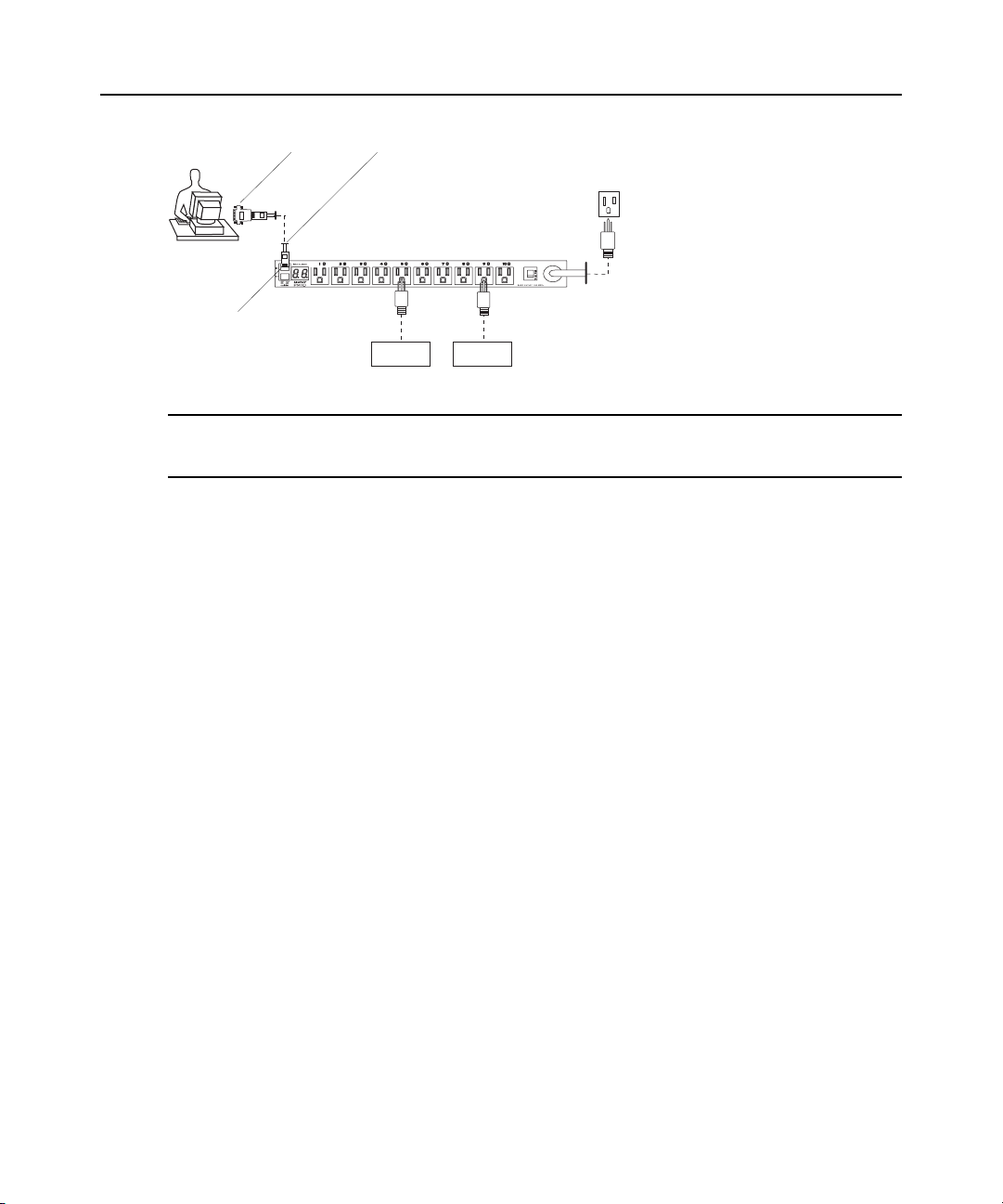
User
RJ-45 CableRJ-45 to DB-9F Adaptor
IN Port
Server Switch
Figure 1.1: Standal one Configur a tion
NOTE: The previous graphic displays the PM IPDU being connected to the local work station with the RJ-45 to
DB-9F adaptor that is shipped with the product. If your work station does not have a DB-9M COM port, you may
need to use a USB serial adaptor in order to connect to the computer’s USB port.
For specific installation instructions, see Rack Mounting the Cyclades PM IPDU on page 16.
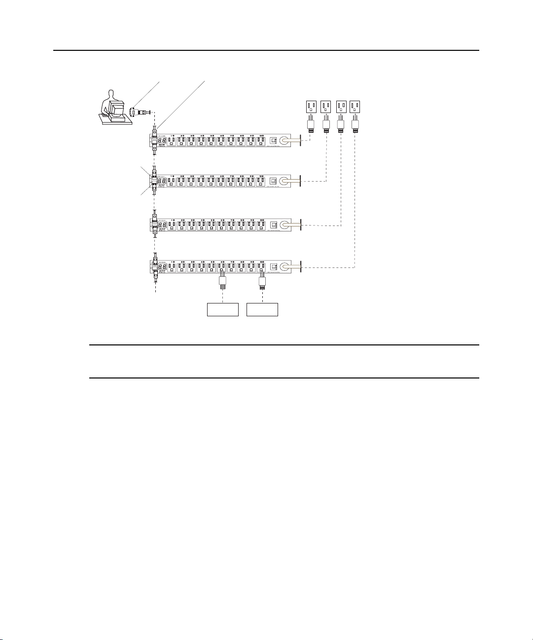
Daisy chained configuration
In a daisy chained configuration, multiple slave PM IPDUs are connected to one another and
managed by a single master PM IPDU. The PMs are linked together with RJ-45 cables connected
to one PM IPDU’s OUT port and the other PM IPDU’s IN port. This example shows four Cyclades
PM IPDUs operating in a daisy chained environment. PM IPDU #1 is connected to the local
workstation and is the “master” PM IPDU, while the other three PM IPDUs are “slaves.”
Chapter 1: Introduction 3
Power Source
Page 16
4 Cyclades PM IPDU Installer/Administrator/User Guide
RJ-45 CableRJ-45 to DB-9F Adaptor
Power Source
User
IN Port
OUT Port
Additional Cyclades PM IPDUs
with up to a total of 128 outlets
can be daisy-chained
Figure 1.2: Daisy Chained Configuration
NOTE: The previous graphic displays the PM IPDU being connected to the local work station with the RJ-45 to
DB-9F adaptor that is shipped with the product. If your work station does not have a DB-9M COM port, you may
need to use a USB serial adaptor in order to connect to the computer’s USB port.
The PM IPDUs in the previous graphic are configured to be used independently of any other
PM IPDU #1
PM IPDU #2
PM IPDU #3
PM IPDU #4
Server Switch
hardware such as the Cyclades ACS console server or Cyclades-TS terminal server.
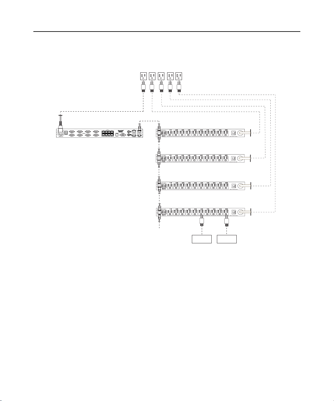
Integrated configuration
In an integrated configuration, the Cyclades PM IPDU is configured to work in conjunction with
one of the following Cyclades management products:
• Cyclades-TS terminal server
• Cyclades ACS console server
• Cyclades OnSite appliance
• Cyclades KVM switch family
A user connects to the Cyclades PM IPDU by accessing the appropriate console port of the
Cyclades management product. In this scenario, software configuration on and monitoring of the
Cyclades PM IPDU is done through the Cyclades management product and not on the PM IPDU
Page 17
Chapter 1: Introduction 5
itself. Visit http://www.cyclades.com/support/downloads.php to find setup and configuration
instructions for the Cyclades management products.
Power Source
PM IPDU #1
AlterPath OnSite
PM IPDU #2
PM IPDU #3
PM IPDU #4
Additional Cyclades PM IPDUs
with up to a total of 128 outlets
can be daisy-chained
Figure 1.3: The Cyclades PM IPDU with a Cyclades Management Device
Server Switch
An integrated environment offers the following advantages:
• IT professionals may power down, power up, and reboot network devices using the same
console management session from any location via telnet, Secure Shell (SSHv2), or through a
secure web session. This may all be done without the need for ph ysical access to the hardware.
• Ethernet connection is available through the Cyclades management products to which the
Cyclades PM IPDU is connected. When used with Cyclades management products, the
Cyclades PM IPDU allows you, via a configurable hotkey, to reboot servers without leaving
your telnet/ssh se ssion.
• The Cyclades PM IPDU inherits the security of the console server to which it is connected.
Daisy chaining PM IPDUs with the Cyclades ACS console server or Cyclades TS terminal server is
similar to the daisy chained configuration as described in Daisy chained configuration on page 3;
Page 18

6 Cyclades PM IPDU Installer/Administrator/User Guide
however, in the integrated configuration, the first Cyclades PM IPDU is connected to a Cyclades
management device instead of a workstation.
Accessing the System Console
Users and administrators may access the Cyclades PM IPDU either by making a direct console
connection to the PM IPDU’s IN port or by connecting the PM IPDU to a Cyclades console or
KVM switch management device.
Direct console access
While using the PM IPDU device independently of other Cyclades devices, local users may
connect directly to the system console port (the IN port) of the Cyclades PM IPDU using the
console cable with the corresponding adaptor(s).
For more information about connecting directly to the PM IPDU’s console, see Making a Direct
Connection for Console Access on page 20.
Console access through a management device
While integrating the PM IPDU device with a Cyclades console or KVM management device such
as the Cyclades ACS console server or the Cyclades OnSite, remote users may access the Cyclades
PM IPDU's console port through one of the following interfaces:
• Menu-driven interface - After using telnet or SSH to access the console port equivalent to the
managed device on the con so le s erver, type the power manag e ment hotkey (
to bring up a power management menu on the same screen.
• Web interface - Once you are logged into the management device web interface, access the
power management functionality by selecting a Power Management or IPDU Power
Management tab on the Web Manager.
Ctrl+P by default)
See Integration with Cyclades management products on page 2 for more background information
on integrating a PM IPDU with a Cyclades management device, or refer to the appropriate user
documentation for instructions on accessing the PM IPDU console through your specific Cyclades
management device.
To connect a Cyclades PM IPDU to an Avocent DSR switch:
Use the included RJ-45 cable adaptor to connect a Cyclades PM IPDU to an Avocent DSR switch.
1. Plug the male end of the adaptor into the DSR switch’s SPC port.
2. Plug one end of a straight through Cat 5 cable into the female end of the adaptor.
3. Plug the other end of the Cat 5 cable into the PM IPDU’s In port.
Page 19

Component Overview
General features are common among all products, in the Cyclades PM IPDU family:
• 128 KB flash memory
•8 KB RAM
• Two RJ-45 RS-232 interfaces
• Digital global current display with two digits and seven segments
• LEDs monitoring ON/OFF status for each port
• Audible over current alarm
• 8-bit Microcontroller-equipped
The following sections list features that are specific to each model:
• Cyclades PM8 IPDU on page 7
• Cyclades PM8i IPDU on page 8
• Cyclades PM10 IPDU on page 8
• Cyclades PM10i IPDU on page 9
• Cyclades PM10i-L30A IPDU on page 9
• Cyclades PM10i-32A IPDU on page 9
• Cyclades PM10i-32Au IPDU on page 10
• Cyclades PM20 IPDU on page 10
• Cyclades PM20i IPDU on page 10
Chapter 1: Introduction 7
If needed, see Appendix A: Specifications on page 63 for more electrical, hardware and
environment details about each model. See Supplied with the PM IPDU on page 13.
Cyclades PM8 IPDU
The Cyclades PM8 IPDU has the following features:
• One of the following power plugs:
• 125VAC/15A (NEMA 5-15P)
• 125VAC/20A (NEMA 5-20P)
• 125VAC/20A (NEMA L5-20P)
• Eight 125VAC/15A power receptacles (NEMA 5-15R)
• 125VAC/20A circuit breaker
• Vertical mounting (zero U)
Figure 1.4: Cyclades PM8 IPDU
Page 20
8 Cyclades PM IPDU Installer/Administrator/User Guide
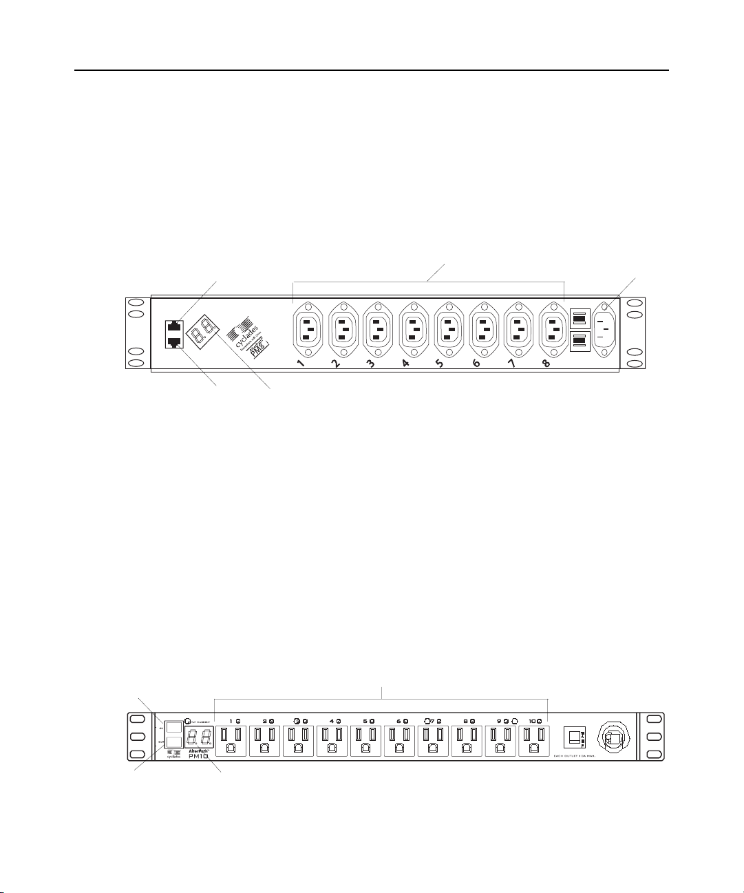
t
Power Outlets (IEC320-C13)
Cyclades PM8i IPDU
The Cyclades PM8i IPDU has the following features:
• One 240VAC/8A power inlet (IEC320-C14). See PM8i-10A IPDU and PM10i-10A IPDU
power cables on page 15 for a list of which power cables are supplied by region.
• Eight 240VAC/8A power receptacles (IEC320-C13)
• 240VAC/10A supplementary protector
• Horizontal (1.5U) mounting
OUT Port
IN Port Digital Current Display
Figure 1.5: Cyclades PM8i IPDU
Cyclades PM10 IPDU
The Cyclades PM10 IPDU has the following features:
• One of the following power plugs:
• 125VAC/15A power plug (NEMA 5-15P)
• 125VAC/20A power plug (NEMA 5-20P)
• 125VAC/20A power plug (NEMA L5-20P)
• 125VAC/30A power plug (NEMA L5-30P)
• Ten 125VAC/15A power receptacles (NEMA 5-15R)
• 125VAC/15A/20A/two 15A circuit breakers
• Horizontal mounting (1U)
Power Inle
IN Port
OUT Port
Figure 1.6: Cyclades PM10 IPDU
Digital Current Display
10 NEMA5-15R Power Outlets
Page 21
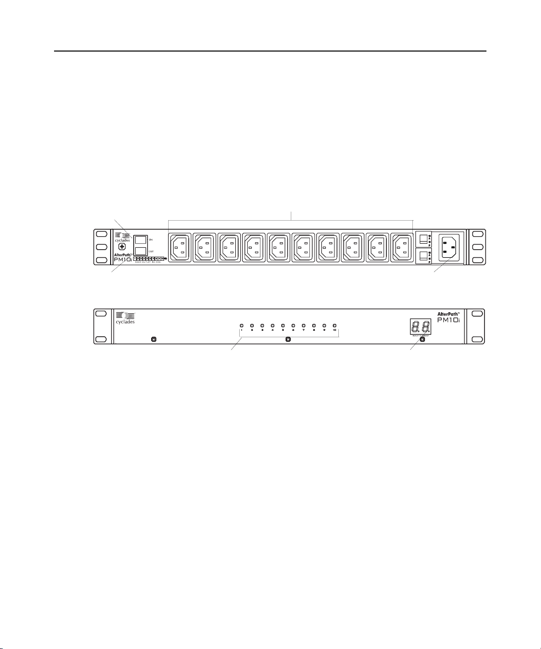
Cyclades PM10i IPDU
10 IEC320-C13 Power Outlets
The Cyclades PM10i IPDU has the following features:
• One of the following power plugs:
• 240VAC/10A power plug (IEC320-C14)
• 240VAC/16A power plug (IEC320-C20)
• Ten 240VAC/10A power receptacles (IEC320-C13)
• 240VAC/10A/20A supplementary protector
• Horizontal (1U) mounting
IN Port
Chapter 1: Introduction 9
OUT Port
Figure 1.7: Back of the Cyclades PM10iIPDU
Figure 1.8: Front of the Cyclades PM10iIPDU
Cyclades PM10i-L30A IPDU
The Cyclades PM10i-L30A IPDU has the following features:
• 30A input power cord. L6-30P plug (USA model)
• Ten 240VAC/10A power receptacles (IEC320-C13)
• Two 240VAC/15A magnetic circuit breakers with “press to reset” function
• Horizontal (1U) mounting
Refer to Figure 1.7 on page 9 and Figure 1. 8 on page 9 for images of the Cy clades
PM10i-L30A IPDU.
Cyclades PM10i-32A IPDU
The Cyclades PM10i-32A IPDU has the following features:
• 32A input power cord; IEC 309 plug.
• Ten 240VAC/10A power receptacles (IEC320-C13)
• Two 240VAC/16A magnetic circuit breakers with accidental-off protection function
IEC320-C14 Power Inlet
Digital Current DisplayPower Outlet LEDs
Page 22

10 Cyclades PM IPDU Installer/Administrator/User Guide
• Horizontal (1U) mounting
Refer to Figure 1.7 on page 9 and Figure 1. 8 on page 9 for images of the Cy clades
PM10i-32A IPDU.
Cyclades PM10i-32Au IPDU
The Cyclades PM10i-32Au IPDU has the following features:
• 32A unterminated input power cord
• Ten 240VAC/10A power receptacles (IEC320-C13)
• Two 240VAC/16A magnetic circuit breakers with accidental-off protection function
• Horizontal (1U) mounting
Refer to Figure 1.7 on page 9 and Figure 1. 8 on page 9 for images of the Cy clades
PM10i-32Au IPDU.
Cyclades PM20 IPDU
The Cyclades PM20 IPDU is available in three models: PM20-15A IPDU, PM20-20A IPDU, and
PM20-30A IPDU. Each model has the following features:
• One of the following power plugs:
• 125VAC/15A power plug (NEMA 5-15P)
• 125VAC/20A power plug (NEMA 5-20P)
• 125VAC/20A power plug (NEMA L5-20P)
• 125VAC/30A power plug (NEMA L5-30P)
• 20 125VAC/15A power receptacles (NEMA 5-15R)
• 125VAC/20A circuit breaker (15A, 20A, and 30A models)
• Vertical mounting (zero U)
1
2
3
......
4
Figure 1.9: The Cyclades PM20 IPDU
5
7
6
..... .. ..... ..
8
9
10
11
12
13
14
15
16
17
18
19
20
Cyclades PM20i IPDU
The Cyclades PM20i IPDU has the following features:
• One of the following power plugs:
• 240VAC/16A power plug (IEC320-C20)
• 240VAC/20A power plug (IEC320-C20)
• Twenty 240VAC/10A power receptacles (IEC320-C13)
• 240VAC/20A supplementary protector with a “press to reset” function on the L30A models
• 240VAC/15A branch circuit breaker with accidental-off protected feature (30A model)
Page 23

• Vertical mounting (zero U)
Figure 1.10: The Cyclades PM20i IPDU, PM20i-32A IPDU and PM20i-32AU IPDU
Cyclades PM20i-32A IPDU
The Cyclades PM20i-32A IPDU has the following features:
• 32A input power cord; IEC 309 plug.
• Twenty 240VAC/10A power receptacles (IEC320-C13)
• 240VAC/two 16A magnetic circuit breakers with accidental-off protection function
• Vertical mounting (zero U)
Refer to Figure 1.10 on page 11 for an image of the Cyclades PM20i-32A IPDU.
Cyclades PM20i-32Au IPDU
The Cyclades PM20i-32Au IPDU has the following features:
• 32A unterminated input power cord
• Twenty 240VAC/10A power receptacles (IEC320-C13)
• 240VAC/two 16A magnetic circuit breakers with accidental-off protection function
• Vertical mounting (zero U)
Chapter 1: Introduction 11
Refer to Figure 1.10 on page 11 for an image of the Cyclades PM20i-32Au IPDU.
Page 24

12 Cyclades PM IPDU Installer/Administrator/User Guide
Page 25

CHAPTER
Installation
2
Getting Started
Collect the following equipment prior to installing and configuring the Cyclades PM IPDU in
standalone configuration:
• One or more RJ-45 to RJ-45 straight-through cables
• An RJ-45 to DB-9F straight-through adaptor
• A PC running a terminal emulation program
See the following section for the list of other necessary items that come with the PM IPDU.
Supplied with the PM IPDU
13
All PM IPDU models are shipped with the PM IPDU itself along with the items shown in
Table 2.1. The entry for each part provides an illustration, its part number (P/N), description, and
purpose. You may use check box es to check off each item, and you may us e th e par t nu mbers from
this table to reorder any of the parts.
Table 2.1: PM IPDU Shipping Box Contents, Part Numbers and Description
P/N Description Purpose
PAC0225 Cyclades PM IPDU Quick
Start Guide
CAB0018 RJ-45 to RJ-45 7ft. straight through
CAT5 cable
ADB0200 RJ-45 to DB-9F straight-
through adaptor
Basic installation guide for experienced users in
printed format.
Used for the following:
Along with an adaptor, to connect a terminal or PC to
the IN port. See To access the console: on page 21.
To connect to a Cyclades console or KVM
management device.
To connect to another Cyclades PM IPDU in a daisy
chain. See To daisy chain a PM IPDU: on page 19.
Along with an RJ-45 cable, used to connect a terminal
or PC to a PC’s COM port. See T o access the console:
on page 21.
Page 26

14 Cyclades PM IPDU Installer/Administrator/User Guide
Table 2.1: PM IPDU Shipping Box Contents, Part Numbers and Description (Continued)
P/N Description Purpose
CON0132 RJ-45 loopback connector In case the administrator forgets the admin's
210105 PM IPDU to DSR switch cable
adaptor
HAR0220 2 mounting brackets with 8 screws
(2 spares). For PM10 IPDU and
PM10i IPDU
HAR0302 2 mounting brackets with 5 screws
(1 spare). For PM8i IPDU
password, this is used to place in the OUT port to gain
temporary access to the box using the factory default
password.
See T o reset the admin password using the loopback
connector: on page 25.
Used to connect Cyclades PM IPDU to an Avocent
DSR switch.
Use to mount the Cyclades PM10 IPDU and PM10i
IPDU to a rack or wall. See To mount the Cyclades
PM8i IPDU, PM10 IPDU or PM10i IPDU: on page 18.
Use to mount the Cyclades PM8i IPDU to a rack or
wall. See To mount the Cyclades PM8i IPDU, PM10
IPDU or PM10i IPDU: on page 18.
See the following section for a list of power cables shipped with specific PM IPDU models.
Modular input power cables for the PM IPDU
If your PM IPDU model does not have a fixed power input cable, it may ship with one of the
modular cables listed in the following sections. Depending on your site’s location, the modular
input power cables included in the box vary. See the following sections to find the input cable that
should ship with your PM IPDU product:
• PM8i-10A IPDU and PM10i-10A IPDU power cables on page 15
• PM10i-15A IPDU power cables on page 16
• PM10i-16A IPDU and PM 20i-16A IPDU power cables on page 16
NOTE: The Cyclades PM 10i-32Au IPDU ships with an unterminated power cord. If necessary, your Cyclades
representative may provide guidelines on approved power plug installation.
Page 27

PM8i-10A IPDU and PM10i-10A IPDU power cables
Table 2.2: PM8i-10A IPDU and PM10i-10A IPDU Power Cables
P/N Country/Region
CAB0089 US
CAB0055 Australia and New Zealand
CAB0087 Continental Europe
CAB0088 United Kingdom and Ireland
Chapter 2: Installation 15
Page 28

16 Cyclades PM IPDU Installer/Administrator/User Guide
PM10i-15A IPDU power cables
Table 2.3: PM10i-15A IPDU Power Cables
P/N Country/Region
CAB0191 US
PM10i-16A IPDU and PM 20i-16A IPDU power cables
Table 2.4: PM10i-16A IPDU and PM 20i-16A IPDU Power Cables
P/N Country/Region
CAB0193 Continental Europe
CAB0192 Australia and New Zealand
CAB0194 United Kingdom and Ireland (fuse limited to 13A as per BS1363)
PM10i-20A IPDU and PM 20i-20A IPDU power cables
Table 2.5: PM10i-20A IPDU and PM 20i-20A IPDU Power Cables
P/N Type
CAB197 US
CAB0195 US
CAB0198 US
NEMA L6-20P
NEMA 5-20P
NEMA L5-20P
Optional outlet cable package
The following cable packages may be ordered separately for the IEC PM IPDU models:
• 8-outlet cables (C13 female to C14 male) (ACS0040).
• 10-outlet cables (C13 female to C14 male) (ACS00046).
Rack Mounting the Cyclades PM IPDU
You may mount the PM IPDU on a rack or wall or place it on a desktop or other flat surface. Two
brackets are supplied with six Phillips screws for attaching the brackets to the PM8i IPDU, the
PM10 IPDU and the PM10i IPDU for mounting. The PM8 IPDU has built-in brackets.
• If you are not mounting the PM IPDU, place the PM IPDU on a desk or table.
Page 29
• If you are mounting the PM IPDU, obtain a Phillips screwdriver and app ropriate nuts and bolts
before starting the following procedure.
NOTE: When mounting a Cyclades PM IPDU zero U model to a wall stud, securely mount it by using a #10 or
larger screw or use a drywall fastener rated min. 25 lb. (11.34 kg).
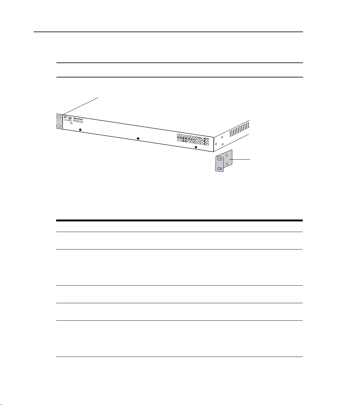
The following graphics depict the orientation of the brackets for front rack mounting PM IPDU.
Figure 2.1: Rack Mounting a Cyclades PM10 IPDU, PM10l IPDU and PM8iIPDU
Installati on envi ronment
When installing the PM IPDU, ensure that the following environment specifications are met.
Chapter 2: Installation 17
Bracket
Table 2.6: PM IPDU Optimum Installation Environment
Environment Factor Recommendation
Temperature The manufacturer's maximum recommended ambient temperature for the
Cyclades PM IPDU is 122 ºF (50 ºC).
Elevated Operating Ambient
Temperature
Reduced Air Flow Installation of the equipment in a rack should be such that the amount of air
Mechanical Loading Mounting of the equipment in the rack should be such that a hazardous
Circuit Overloading Consideration should be given to the connection of the equipment to the
If the Cyclades PM IPDU is installed in a closed or multi-unit rack assembly,
the operating ambient temperature of the rack environment may be greater
than room ambient temperature. Therefore, consideration should be given
to installing the equipment in an environment compatible with the
manufacturer’s maximum rated ambient temperature. See above.
flow required for safe operation of the equipment is not compromised.
condition is not achieved due to uneven mechanical loading.
supply circuit and the effect that overloading of circuits might have on
overcurrent protection and supply wiring. Appropriate consideration of
equipment nameplate ratings should be used when addressing
this concern.
Page 30
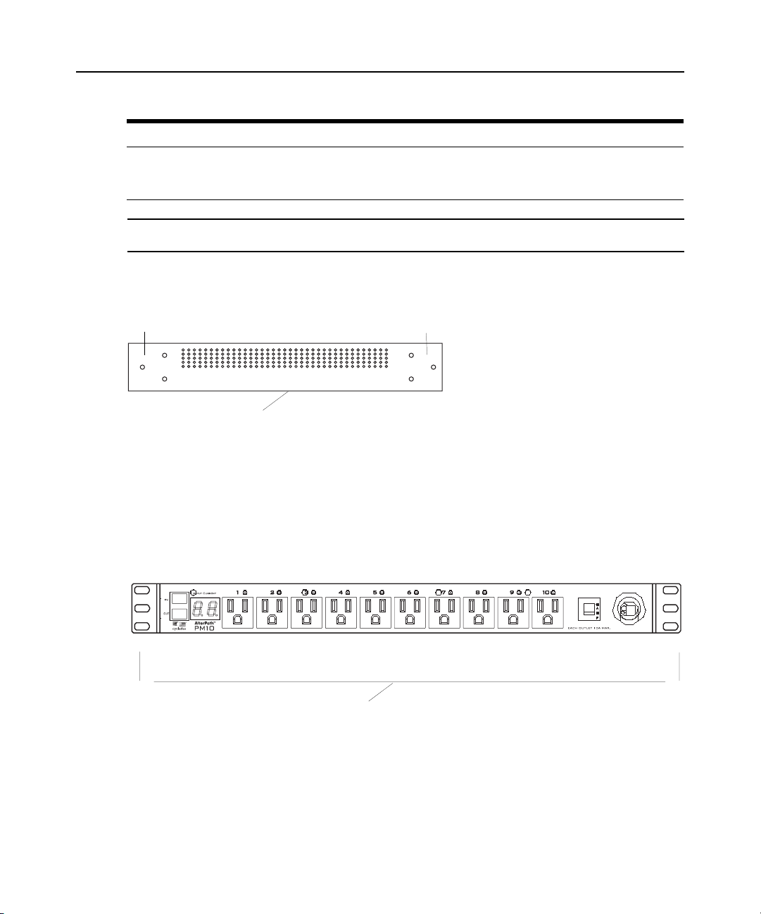
18 Cyclades PM IPDU Installer/Administrator/User Guide
Holes for Front Mounting Holes for Back Mounting
Table 2.6: PM IPDU Optimum Installation Environment (Continued)
Environment Factor Recommendation
Reliable Grounding Reliable grounding of rack-mounted equipment should be maintained.
NOTE: Install a Cyclades PM IPDU zero U model in a location where there is an adjacent and accessible wall
socket outlet.
Particular attention should be given to supply connections other than direct
connections to the branch circuit, such as power strips or extension cords.
To mount the Cyclades PM8i IPDU, PM10 IPDU or PM10i IPDU:
1. Locate the appropriate sets of holes on the PM IPDU.
Side of the PM IPDU
Figure 2.2: Rack Mounting Holes on the PM8i IPDU, PM10 IPDU and PM10i IPDU
2. Connect the two supplied brackets to the PM IPDU, connecting one bracket to each side of
the box.
3. For each bracket, insert a screw through each of the three holes on the bracket into the
appropriate holes at either end of the PM IPDU.
The following figure shows the bracket flanges on the front of the PM IPDU after the brackets
are installed.
Brackets
Figure 2.3: PM10 IPDU with Mounting Brackets Installed
4. Use a Phillips screwdriver to tighten the screws.
5. Use the mounting hardware recommended for your rack to mount the PM IPDU on a rack as
illustrated in the following graphic.
Page 31

Chapter 2: Installation 19
NOTE: The suggested minimum screw size for wall-mounting the Cyclades PM IPDUs is #10 (4.8 mm or 0.19 in
or 3/16 in) or larger. The RJ-45 cable included in the Cyclades PM IPDU package is minimum flame rated VW-1
or FT-1 and has a maximum length of 10 feet (3 meters).
Nodes
PM8i IPDU, PM10 IPDU or PM10i IPDU
Cyclades ACS Console Server,
Cyclades TS Terminal Server,
Cyclades KVM Switch or
Cyclades OnSite Appliance
Switch
Router
PBX
UPS
UNIX server
Figure 2.4: Rack Mount for the Cyclades PM8i IPDU, PM10 IPDU or PM10i IPDU
Daisy Chaining PM IPDUs
You may man age a maximum of 128 outlets from a single work station by connecting s lave PM
IPDUs to the master PM IPDU device. See Making a Direct Connection for Console Access on
page 20 for more details.
To daisy chain a PM IPDU:
This procedure assumes that a master PM IPDU is already connected to a work station or to a
Cyclades console server, terminal server, KVM switch, or OnSite appliance.
1. Connect one end of an RJ-45 cable to the OUT port of the main Cyclades PM IPDU, which is
connected to a work station or to a Cyclades console or KVM device (master).
2. Connect the other end of the RJ-45 cable to the IN port of the secondary Cyclades
PM IPDU (slave).
Ethernet
Page 32

20 Cyclades PM IPDU Installer/Administrator/User Guide
3. To connect another PM IPDU to the slave, connect one end of an RJ-45 cable to the OUT port
of the last PM IPDU in the chain.
4. Repeat Step 3 until you have connected the desired number of PM IPDUs.
You may control up to 128 power outlets in any combination of PM IPDU models.
Plugging Devices Into PM IPDU Outlets
In order to control power to a device, the device must be plugged into one of the PM IPDU’s
power outlets.
To plug devices into PM IPDU outlets:
Plug all the devices you want to control into the Cyclades PM IPDU outlets.
Powering Up the PM IPDU
Power up the Cyclades PM IPDU in order to begin managing power to its connected devices.
To power up the PM IPDU:
Plug the power cable into an adjacent AC power source.
NOTE: The Cyclades PM IPDU must be powered by a receptacle with adequate circuit protection.
Making a Direct Connection for Console Access
The system administrator must specify bas ic s ettings on the PM IPDU bef ore u ser s may co nnect to
and manage the unit and the connected devices. To prepare to perform necessary basic
configuration, make a direct connection to the PM IPDU by connecting a terminal or computer to
the IN port as depicted in the following graphic.
Page 33

RJ-45 to
DB-9F
RJ-45
Cable
IN Port
Figure 2.5: Connecting a Local Work Station to the Cyclades PM IPDU
To access the console:
Chapter 2: Installation 21
Local
Workstation
Cyclades PM IPDU
Perform the following steps to connect a computer to the console port of the PM IPDU. This
procedure assumes that you know how to use a terminal emulation program.
On a PC, ensure that HyperTerminal or another terminal emulation program is installed on the
Windows operating system. On a computer running a UNIX -based operating system, such a s
Solaris or Linux, make sure that a compatible terminal emulator, such as Kermit or Minicom,
is installed.
1. Connect an RJ-45 serial cable to the IN port on the PM IPDU.
2. Connect the other end of the RJ-4 5 s erial cab le to the RJ-45 to DB-9F straight through adaptor
shipped with the PM IPDU.
3. Connect the adaptor to a DB-9 serial port on a computer.
4. You may need to use a USB serial adaptor in order to connect to the computer.
5. Using a terminal emulation program installed on a computer, start a session. The terminal
should be set to ANSI emulation, 9600 bps, 8 bits, no parity, 1stop bit and no flow control.
Page 34

22 Cyclades PM IPDU Installer/Administrator/User Guide
To log into the PM IPDU through the console (IN port):
From your terminal emulation application, log into the console port as admin.
AlterPath PM
Copyright (c) 2002-2006 Avocent Corporation
V 1.9.0 Jun 21, 2006
[PM]: IPDU: 1
[PM]: OUT: 10
Username: admin
The default password is pm8. If the password has been changed from the default, use the
new password.
If this is a first-time installation, see Initial Configuration Using the Command Prompt on page 24
for instructions on changing the default password, adding users, and assigning outlets to users.
See Command Line Interface on page 31, for procedures on logging in and using the console
commands to manage power on connected devices.
Page 35

CHAPTER
3
The Cyclades PM IPDU may be configured by any one of three methods:
• Command Prompt - Full configuration capabilities.
• Browser - Available only when the PM IPDU is connected directly to an AUX port on a KVM
switch or OnSite appliance or connected directly to a serial console port on an ACS console
server, TS terminal server or OnSite appliance. This menu allows you to invoke the various
PM IPDU operations, such as cycling, switching on, switching off and basic configurations of
the power management session to communicate with the PM IPDU. Only a limited number of
parameters may actually be changed and saved to the PM IPDU.
• T ex t- based men u - Available only when used in an integrated configuration. This menu allows
you to invoke the various PM IPDU operations such as cycling, switching on, switching off
and more.
23
Configuration
The following sections offer basic instructions for configuring, restoring the admin password, and
uploading firmware on the Cyclades PM IPDU for either the standalone or the daisy
chained configuration.
For information about integrated use with the Cyclades ACS console server, Cyclades TS terminal
server, Cyclades KVM switch or the Cyclades OnSite appliance, refer to the documentation
relevant to each product family.
Default Configuration Parameters
The Cyclades PM IPDU’s default configuration is as follows:
•User is admin.
• admin user’s password is pm8.
• All outlets are un-named.
• All outlets are unassigned to user.
• All outlets are turned on.
• All outlets are unlocked.
Page 36

24 Cyclades PM IPDU Installer/Administrator/User Guide
Initial Configuration Using the Command Prompt
To configure the PM IP DU, yo u mu st have a w ork st ation co nnected to th e con sole (In ) p ort on the
PM IPDU and be logged in as the admin user. See Making a Direct Connection for Console Access
on page 20 for instructions on conn ecting to t he consol e. If needed, refer to Chapte r 4 begin ning on
page 31.
To change the default password:
If the default pm8 password is still in use, change the admin password.
NOTE: Changing the default password closes a security hole that could be easily exploited.
1. Log in to the PM IPDU.
2. Enter the factory default username /passwor d
case sensitive) is allowed.
3. Enter the
passwd command.
4. Enter a new password when prompted.
T o create users with the adduser command:
1. Login to the PM IPDU.
2. Enter the
adduser command followed by the new username.
3. Enter the password whe n prompted.
admin/pm8. A maximum of eight character s (not
T o assign outlets to users with the assign command:
1. Login to the PM IPDU.
2. Enter the
assign command followed by the outlet number(s) and username.
Example:
pm>assign 2 jane
Outlet 2 assigned to jane.
To name the outlets with the name command:
1. Login to the PM IPDU.
2. Enter the
name command followed by the outlet number and desired name of the outlet.
Example:
pm>name 2 chispa
2: Outlet now named chispa
Page 37

T o save the configuration with the save command:
1. Login to the PM IPDU.
2. Enter the
save command to save the configuration.
Resetting the Admin Password
In the event the administrator wants to reset the password for the Cyclades PM IPDU (for example,
if the administrator forgets the admin password), then the loopback connector that is shipped with
the Cyclades PM IPDU may be used for temporary access to the PM IPDU.
To reset the admin password using the loopback connector:
Chapter 3: Configuration 25
1. If you are not logged out, log out by enteri ng
exit. (Y o u mus t be at the logi n pro mpt for this to
work.)
2. Attach the loopback connector.
Connect the loopback connector shipped with the product to th e OUT port of the Cyclades PM
IPDU. If necessary, disconnect any cables connected to the OUT port of the Cyclades PM
IPDU to allow for the connection of the loopback.
3. Wait one minute and then check the display.
If you are watching the Cyclades PM IPDU's console output (using HyperTerminal or
Minicom), messages like the ones shown below are displayed:
AlterPath PM
Copyright (c) 2002-2006 Avocent Corporation
V 1.9.0 Jun 21, 2006
Username: [PM]: DCD went ON on output port of IPDU #1
[PM]: Trying to detect loopback cable on OUT port of IPDU #1
[PM]: Loopback detected. Changing administrator password to default.
[PM]: Please remove the loopback cable now.
[PM]: DCD went OFF on output port of IPDU #1
[PM]: IPDU: 1
[PM]: OUT: 8
4. Remove the loopback connector.
After one minute, you may rem ove the lo opback connec tor fr om the OUT p ort of the C yclades
PM IPDU. Now the password for the user admin is reset to the default (pm8), and you sh ould
be able to log into the Cyclades PM IPDU using the default username/password.
5. Change the password for the admin, if desired, by entering the
6. Enter the
save command to save the configuration.
passwd command.
Page 38

26 Cyclades PM IPDU Installer/Administrator/User Guide
7. If you need to recover the password of many Cyclades PM IPDUs connected in a daisy chain,
go to step 1 and perform the procedure on each Cyclades PM IPDU in the chain.
Upgrading the Cyclades PM IPDU Firmware
Starting with version 1.1 .0, the Cyclades PM IPDU firmware may be u pg raded thro ugh i t s IN po rt.
The upgrade procedure described here is only valid for units that are currently running firmware
versions 1.3.0 or greate r. If your Cyclades PM IPDU is running an older firmware version, please
follow the instructions in the manual that corresponds to the firmware currently installed on the PM
IPDU. Visit ftp://ftp.cyclades.com/pub/cyclades/alterpath/pm/doc/ for older versions of
this manual.
T o upgrade PM IPDU firmware:
1. Download the new Cyclades PM IPDU firmware from the Cyclades web site.
After downloading the Cyclades PM IPDU firmware file, save it to the workstation connected
to the Cyclades PM IPDU console (IN port).
2. Using either Hyperterminal or Minicom, log into the Cyclades PM IPDU as admin and type in
the command:
pm>upgrade <IPDU#>
If you are currently logged in as a different user, log out and then login as admin.
The <IPDU#> is the number of the IPDU to which you want to upgrade the firmware. If you have
only one Cyclades PM IPDU, type
chain, type
NOTE: If you have a daisy chain and you want to upgrade all units, you should start from the last unit and work
your way tow a r d s th e fi r st.
upgrade 3 or upgrade 2 depending on which unit you want to upgrade.
upgrade 1. If you have, for instance, three units in a daisy
Page 39

Chapter 3: Configuration 27
After the upgrade command is executed, the boot loader menu is displayed at the console, as
shown below :
pm>upgrade 1
-----------------------------
Copyright (c) 2003 Cyclades Corporation
AlterPath PM/KVM Boot Loader Version 1.1
----------------------------Boot Menu
1. Upgrade Firmware.
2. Boot Firmware.
-----------------------------
Enter choice (1 or 2): 1
3. At the boot loader menu, select option 1 to upgrade the firmware.
The boot loader erases the firmware currently in the unit and asks you to upload the new
firmware, as shown below:
----------------------------Copyright (c) 2003 Cyclades Corporation
AlterPath PM/KVM Boot Loader Version 1.1
----------------------------Boot Menu
1. Upgrade Firmware.
2. Boot Firmware.
----------------------------Enter choice (1 or 2): 1
Erasing firmware...done.
Downloading image. Please send file in 10 seconds.
4. Use your terminal emulator program to upload the Cyclades PM IPDU firmware file to the PM
IPDU using the Xmodem protocol.
To use HyperTerminal in W indows:
1. From the top menu select Transfer-Send.
The Send File pop-up window appears.
Page 40

28 Cyclades PM IPDU Installer/Administrator/User Guide
Figure 3.1: Sending Firmware using HyperTerminal
2. Click the Browse button to set the proper path for the Cyclades PM IPDU firmware file located
on your work station.
NOTE: You must browse for the proper file and click the Send button within 10 seconds of selecting
Transfer-Send. If you fail to do so, an error message will appear and the transmission will fail. You will then be
given another 10-second window in which to repeat steps 1. through 4.
3. Select Xmodem as the protocol.
4. Click on the Send button.
To use Minicom in Linux:
1. From the main screen, press
Ctrl+A S (for sending files).
The Upload pop-up window appears.
2. Select xmodem as the protocol.
The Select a file for upload window appears.
3. Move the cursor next to the Cyclades PM IPDU firmware file for upload, and press the
Spacebar to tag it. See Figure 3.2.
4. Press
Enter to start the file transfer.
Page 41

Chapter 3: Configuration 29
Figure 3.2: Sending Firmware using Minicom
If you use a different terminal emulator, please refer to the documentation provided by the
manufacturer on how to transfer files using the xmodem protocol.
If the file transfer is successful, the Cyclades PM IPDU console displays the login prompt. At this
point, the upgrade process of the unit is complete; you may log into the Cyclades PM IPDU and
perform actions as usual.
If the file transfer fails, an error message appears on the PM IPDU console, and the boot loader
menu is displayed again so you may redo the firmware upgrade process.
The screen would be similar to the one shown below:
Erasing firmware...done.
Downloading image. Please send file in 10
seconds. error.
----------------------------Copyright (c) 2003 Cyclades Corporation
AlterPath PM/KVM Boot Loader Version 1.1
----------------------------Boot Menu
1. Upgrade Firmware.
2. Boot Firmware.
----------------------------Enter choice (1 or 2):
Page 42

30 Cyclades PM IPDU Installer/Administrator/User Guide
In this case, select option 2 from the menu and repeat the firmware upload procedure. If the
problem persists, contact Technical Support for assistance.
Page 43

CHAPTER
Command Line Interfa ce
4
When using the Cyclades PM IPDU independently of other Cyclades products, users and
administrators may access the PM IPDU command line interface through a terminal emulation
program by making a console connection from a local computer to the IN port on the PM IPDU.
See To access the console: on page 21 for instructions.
PM IPDU User Interface
You may access the PM IPDU user interface by following the instructions provided in To access
the console: on page 21. The men u that ap pears after co nnectin g to the console dep ends on whether
the PM IPDU has booted o r not before you connect.
If you connect to the console before powering up the Cyclades PM IPDU or reboot while
connected, the Boot Menu appears.
31
If the PM IPDU has already booted before you connect to the PM IPDU through the console, the
Login prompt appears.
On the Boot Menu, you may enter
Firmware option. The Login prompt appears.
2 (or just wait approximately 12 seconds) to select the Boot
Daisy chained PM IPDUs in the login prompt
Number of PM IPDUs
If no PM IPDUs are daisy chained, the [PM]: IPDU: line appears only once, and the value is 1.
If there are any PM IPDUs daisy chained to the first PM IPDU, the [PM]: IPDU: line appears once
for each PM IPDU in the chain. For each PM IPDU, the value is incremented by 1. The final
appearance of the [PM]: IPDU: line will show the total number of PM IPDUs in the daisy chain.
Number of PM IPDU outlets
If no PM IPDUs are daisy chained, the [PM]: OUT: line appears only once, and the value is equal
to the number of outlets on the PM IPDU.
If there are any PM IPDUs daisy chained to the first PM IPDU, the [PM]: OUT: line appears once
for each PM IPDU in the chain. For each PM IPDU, the value shows the cumulative total of outlets
until the total number of outlets for the entire chain is displayed.
Page 44

32 Cyclades PM IPDU Installer/Administrator/User Guide
Logging in to the PM IPDU
After the Username: prompt, enter your username.
NOTE: If there are daisy chained PM IPDUs, you will need to press Enter after the final [P M]: OUT:
line appears.
After the Password: prompt, enter the password for the unsername entered.
The default user is admin and the default password is pm8.
After a successful login, the PM IPDU command prompt appears after which you may use any of
the commands described in this chapter.
After logging in, the administrator may choose to change his or her password through the passwd
command (seen later). Passwords may be set to null, which indicates that no password is needed.
Commands
All commands are available to the admin user, and most commands are available to regular users
as well.
Table 4.1: User Commands
Regular User Command Regular User Command
current on page 35 off on page 49
currseg on page 37 on on page 50
cycle on page 38 passwd on page 50
exit on page 41 status on page 54
help on page 42 temperature on page 56
humidity on page 43 unlock on page 57
interval on page 46 ver on page 59
list on page 47 voltage on page 60
lock on page 48 whoami on page 61
Page 45

Chapter 4: Command Line Interface 33
The following commands are available only to the admin user.
Table 4.2: Admin User (privileged) Commands
Admin User Command Admin User Command
adduser on page 33 hwocp on page 44
alarm on page 34 id on page 45
assign on page 34 name on page 48
buzzer on page 35 reboot on page 51
currentprotection on page 36 restore on page 53
dbsync on page 39 save on page 53
deluser on page 39 syslog on page 55
display on page 40 unassign on page 57
factory_defaults on page 41 upgrade on page 58
NOTE: When a range of outlets is used in a command and the range spans more than one PM IPDU in a daisy
chain, the range of outlets must not be specified by name. The range of outlets may only be specified by number
in this situation.
adduser
The adduser command adds one username to the internal database. A maximum of eight characters
(not case sensitive) is allowed , and a maximum of eight indivi dual us ers is allow ed. This comm and
is available to the admin user only.
Syntax
adduser <user>
Arguments
<user> username
Examples
To add a user, enter the following.
pm>adduser popper
Password:
Re-enter password:
Username/password set for user popper.
pm>
Page 46

34 Cyclades PM IPDU Installer/Administrator/User Guide
alarm
The alarm command sets and reads the current threshold. This command is available to the admin
user only.
Syntax
alarm | [<IPDU#>|<IPDU_ID>] | <threshold>
Arguments
<IPDU#> IPDU number in a daisy chain
<IPDU_ID> Identification string previously set by the id command.
<threshold> The current threshold is the maximum allowed current on the power strip
no argument Displays alarm status of all PM IPDUs in the daisy chain
Examples
To set the threshold, enter the following.
pm>alarm 1 5.6
Setting alarm threshold on IPDU #1 to 5.6A
pm>alarm 2 7.8
Setting alarm threshold on IPDU #2 to 7.8A
To read the threshold, enter the following.
assign
The assign command assigns an outlet to a given user. The user is then be able to manage such
outlets. This command is available to the admin user only.
Syntax
assign <outlet_number> <user>
Arguments
<outlet_number> Outlet number, such as “5”, outlet name s uch as “sunfire”, or gro up of outlets
such as “1, 3-5”
<user> Desired username
pm>alarm
Alarm threshold on IPDU #1 is 5.6A
Alarm threshold on IPDU #2 is 7.8A
Page 47

Examples
To assign outlet 4, 6, 7, and 8 to user tess, enter the following.
buzzer
The buzzer command displays or changes the buzzer notification status. When set to on, a buzzer
sounds when the current exceeds the threshold. This command is available to the admin user only.
Syntax
buzzer <on|off|status>
Arguments
on Enables buzzer
off Disables buzzer
status Displays the buzzer status
Chapter 4: Command Line Interface 35
pm>assign 4, 6-8 tess
4: Outlet assigned to tess.
6: Outlet assigned to tess.
7: Outlet assigned to tess.
8: Outlet assigned to tess.
Examples
To get the current status of the buzzer notification, enter the following.
To turn buzzer notification on or off, enter the following.
current
The current command displays the total current drawn by Cyclades PM IPDUs and the maximum
current the unit has drawn (current peak). It may also be used to clear the saved peak current value.
pm>buzzer status
Buzzer is ON on IPDU #1
Buzzer is ON on IPDU #2
pm>buzzer on
Buzzer turned ON on IPDU #1
Buzzer turned ON on IPDU #2
pm>buzzer off
Buzzer turned OFF on IPDU #1
Buzzer turned OFF on IPDU #2
Page 48

36 Cyclades PM IPDU Installer/Administrator/User Guide
Syntax
current [<IPDU#>|<IPDU_ID>]|reset
Arguments
<IPDU#> IPDU number in a daisy chain
<IPDU_ID> Identification string previously set by the id command
reset Clears the saved peak current value
Examples
To get the current status for all units, enter the following.
pm> current
IPDU #1: True RMS current: 2.2A. Maximum current: 9.4A
IPDU #2: True RMS current: 2.0A. Maximum current: 10.2A
To get the current status for a specific unit, enter the following.
pm> current 2
IPDU #2: True RMS current: 2.4A. Maximum current: 10.2A
To reset maximum current drawn, enter the following:
pm>current reset
IPDU #1: Clearing maximum recorded current to zero.
IPDU #2: Clearing maximum recorded current to zero.
currentprotection
The currentprotection command turns on and off the over current protection feature. The
overcurrent protection does not let any outlet be turned on if the current drawn by the unit is gr eater
than the current threshold con figur ed with th e command alar m. This command may also be u sed to
display the current protection status. This command is available to the admin user only.
Syntax
currentprotection <on|off|status>
Arguments
on Enables over current protection
off Disables over current protection
status Displays the current protection status
Page 49

Examples
To display current protection status for all units, enter the following.
To enable current protection status for all units, enter the following.
To disable current protection status for all units, enter the following.
currseg
The currseg command lets you view the current for the lower or upper segment of outlets. This
command is only useful for IPDUs with dual current sensors (30A and 32A models). The lower
segment (segment A) would be outlets 1-5 on a PM 10 series IPDU, and the upper segment
(segment B) would be outlets 6-10 on a PM 10 series IPDU.
Chapter 4: Command Line Interface 37
pm>
currentprotection status
IPDU #1: Overcurrent protection is OFF.
IPDU #2: Overcurrent protection is OFF.
pm>currentprotection ON
IPDU #1: Overcurrent protection turned ON.
IPDU #2: Overcurrent protection turned ON.
pm>currentprotection off
IPDU #1: Overcurrent protection turned OFF.
IPDU #2: Overcurrent protection turned OFF.
Syntax
currseg A|B [reset]
Arguments
A|B segment A or segment B
reset Clears the max recorded current for A & B.
Example
To view the current load of segment A, enter the following.
pm>currseg A
IPDU #1: True RMS current for segment A: 0.4A. Maximum current for
segment A: 0.
4A
Page 50

38 Cyclades PM IPDU Installer/Administrator/User Guide
To view the current load of segment B, enter the following.
pm>currseg B
IPDU #1: True RMS current for segment B: 2.5A. Maximum current for
segment B: 2.
5A
To reset the maximum recorded current for A and B, enter the following.
pm>currseg reset
IPDU #1: Clearing maximum recorded current for segment A and B to
zero.
cycle
The cycle command power cycles an outlet or groups of outlets. You may use the outlet number or
the outlet name (see command name for details).
Syntax
cycle all|<outlet_string>
Arguments
all Cycles all outlets in the PM IPDU or PM IPDU daisy chain
<outlet_string> Outlet number, such as “5”, outlet name such as “sunfire”, or group of
outlets such as “1, 3-5”
Examples
To cycle one outlet, enter the following.
pm> cycle 3
3: Outlet turned off.
3: Outlet turned on.
Page 51

To cycle multiple outlets, enter the following.
dbsync
The dbsync command synchronizes the user database for all PM IPDUs in the chain. This
command is available to the admin user only.
Syntax
dbsync
Chapter 4: Command Line Interface 39
pm>cycle 2, 3, 5-7
2: Outlet turned off.
3: Outlet turned off.
5: Outlet turned off.
6: Outlet turned off.
7: Outlet turned off.
2: Outlet turned on.
3: Outlet turned on.
5: Outlet turned on.
6: Outlet turned on.
7: Outlet turned on.
Arguments
none
Examples
To synchronize the user database for all PM IPDUs in the chain, enter the following.
deluser
The deluser command deletes one username from the internal database. This co mmand is av ailabl e
to the admin user only.
Syntax
deluser <user>
Arguments
<user> Desired username
pm>dbsync
pm>Synchronizing user database in IPDU #2.
Page 52

40 Cyclades PM IPDU Installer/Administrator/User Guide
Examples
To delete the user rog, enter the following.
pm>deluser rog
Username deleted.
display
The display command allows logical inversion of the 2-digit, 7-segment display. The purpose of
this command is to allow a PM IPDU to be mounted upside-down. This command is available to
the admin user only.
NOTE: The decimal point will be at the top of the display when the PM IPDU is mounted upside down.
Syntax
display [<IPDU#>|<IPDU_ID> [0|180]]
-or-
display
Arguments
no argument show display status of all PM IPDUs in the daisy chain
<IPDU#> number of the PM IPDU in the chain
<IPDU_ID> Identification string previously set by the id command
0 normal mode (default)
180 inverted display
Examples
To set the display if IPDU #2 to inverted mode, enter the following.
pm>display 2 180
IPDU #2: Display mode set to 180 degrees rotated.
To set the display of IPDU #1 to normal mode, enter the following.
pm>display 1 0
IPDU #1: Display mode set to normal.
Page 53

exit
Chapter 4: Command Line Interface 41
To view the display status, enter the following.
pm>display
IPDU #1: Display mode set to normal.
IPDU #2: Display mode set to 180 degrees rotated.
IPDU #3: Display mode set to show current and cycle each 2 seconds.
The exit command exits the session.
Syntax
exit
Arguments
none
Examples
To exit the current session, enter the following.
pm>exit
AlterPath PM
Copyright (c) 2002-2006 Avocent Corporation
V 1.9.0 Jun 21, 2006
Username:
factory_defaults
The factory_defaults command resets the unit to its factory configuration so that all outlets are on,
unlocked, unnamed, and no users are created. When used with a daisy chain, and no argument is
given, this command resets all units in the chain. This command is available to the admin user only.
Syntax
factory_defaults [<IPDU#>|<IPDU_ID>]
Arguments
no argument resets all PM IPDUs in the daisy chain to factory default
<IPDU#> number of the PM IPDU in the chain
<IPDU_ID> Identification string previously set by the id command
Page 54

42 Cyclades PM IPDU Installer/Administrator/User Guide
Examples
To reset the factory defaults, enter the following.
pm>factory_defaults 1
Setting configuration to defaults on IPDU #1
1: Outlet turned on.
2: Outlet turned on.
3: Outlet turned on.
4: Outlet turned on.
5: Outlet turned on.
6: Outlet turned on.
7: Outlet turned on.
8: Outlet turned on.
Saving configuration to flash on IPDU #1 ... done.
help
The help command displays the system help message for all commands or for a single command
when specified.
NOTE: When the admin user is logged in, the help command displays all commands. When a regular user is
logged in, the help command displays only the regular user commands.
Syntax
<command> help
-or-
help
Arguments
<command> Any available command
Examples
To view the system help message for a specific command, enter the command followed by
pm>syslog help
Usage: syslog <on|off|status>
Turn the syslog messages on the console on or off
help.
Page 55

Chapter 4: Command Line Interface 43
To view the system help message for all commands, enter the following.
pm>help
Available commands:
adduser alarm assign
buzzer current currentprotection
currseg cycle dbsync
deluser display exit
factory_defaults help hwocp
humidity id interval
list lock name
off on passwd
reboot restore save
status syslog temperature
unassign unlock upgrade
ver voltage whoami
NOTE: To get detailed help on the commands listed above type
'<command> help';
NOTE: Some commands accept as input a data type called
<outletString>. <outletString> is a string representing
one or more outlets. This string can be:
- one single outlet.
Examples: on 3 (turn on outlet 3);
off router (turn off the outlet called router).
- a group of outlets.
Examples: status 1,3,5 (get status of outlets 1, 3 and 5);
lock 2,5-7 (lock the outlets 2, 5, 6 and 7).
humidity
The humidity command displays the Cyclades PM IPDU’s surrounding humidity and the
maximum humidity the IPDU has registered (humi dity peak). It may also be used to clear the saved
peak humidity value. This command only works on PM IPDU models with a humidity sensor.
Syntax
humidity [<IPDU#>|<IPDU_ID>]|reset
Page 56

44 Cyclades PM IPDU Installer/Administrator/User Guide
Arguments
<IPDU#> IPDU number in a daisy chain
<IPDU_ID> Identification string previously set by the id command
reset Resets the maximum humidity registered
Examples
To get the humidity for all units in a daisy chain, enter the following.
pm> humidity
IPDU #1: humidity: 42.3%. Maximum: 58.7%
IPDU #2: humidity: 44.0% Maximum: 72.6%
IPDU #3: Does not have humidity sensor.
To get the humidity for specific unit, provide the unit number as an argument, enter the following.
pm> humidity 2
IPDU #2: humidity: 44.0% Maximum: 72.6%
To reset the maximum humidity registered, use reset as a argument, enter the following.
pm>humidity reset
IPDU #1: Clearing maximum recorded humidity to zero.
IPDU #2: Clearing maximum recorded humidity to zero.
hwocp
The hwocp command checks the status of the hardware overcurrent protection. When overcurrent
protection is on, the power is shut off. When the overcurrent protection is off or reset, the power is
on and the PM IPDU is running in normal mode. If no string identifying the IPDU is given, all PM
IPDUs in the daisy chain are affected by this command. This command is available to the admin
user only.
Syntax
hwocp [<IPDU#>|<IPDU_ID> [reset]]
Arguments
<IPDU#> IPDU number in a daisy chain
<IPDU_ID> Identification string previously set by the id command
reset turn overcurrent protection off (normal operation)
Page 57

id
Chapter 4: Command Line Interface 45
Examples
To check the hardware overcurrent status of IPDU #1, enter the following.
pm>hwocp 1
IPDU #1: HW overcurrent protection is OFF.
To reset the hardware overcurrent protection, enter the following.
pm>hwocp 1 reset
IPDU #1 was reset
The id command sets or displays the ID of a PM IPDU. A maximum of 16 characters (not case
sensitive) is allowed. Spaces, numbers, and special characters are allowed. This command is
available to the administrator user only.
This command works in a daisy chain.
Syntax
id [<IPDU#>] [<IPDU_ID>]
-or-
id [<IPDU_ID>] [<IPDU_ID>]
-or-
id
Arguments
<IPDU#> IPDU number in a daisy chain
<IPDU_ID> Identification string previously set by the id command
If <IPDU_ID> follows <IPDU#>, or if the <IPDU_ID> parameter is typed twice, the latest entry of
the <IPDU_ID> parameter updates the ID string.
no argument Displays the IDs of all PM IPDUs in the daisy chain
Examples
To set the ID of PM IPDU 1 R&D, enter the following.
pm>id 1 R&D
IPDU #1: id = R&D
Page 58

46 Cyclades PM IPDU Installer/Administrator/User Guide
To display the ID of PM IPDU 2, enter the following.
pm>id 2
IPDU #2: id = QA
To rename an ID to “sammy,” using an existing ID “QA,” enter the following.
pm>id QA sammy
IPDU #2 = sammy
To display the IDs of all PM IPDUs in the daisy chain, enter the following.
pm>id
IPDU #1: id = R&D
IPDU #2: id = QA
interval
The interval command configures the power up interval for each outlet in the sys tem. The power up
interval of an outlet is the time (in seconds) the unit will wait, after turning this outlet on, to turn on
any other outlet. This command is available to the admin user only.
Syntax
interval <outlet_number> <duration>
Arguments
<duration> Sets the power up interval of outlets. Valid intervals are from 0 to 100. Default
value is 0. 5
NOTE: When this value is set to 0.0, there is still a power up interval of approximately 0.1 seconds
between outlets.
<outlet_number> Outlet number, such as “5”, outlet name such as “sunfire”, or group of
outlets such as “1, 3-5”
Examples
To display the interval of outlet 1, enter the following.
pm>interval 1
1: Outlet power on interval is 0.0 sec.
Page 59

list
Chapter 4: Command Line Interface 47
To set the interval of outlets 2, 4, 5, and 6 to a value of 2.4, enter the following.
pm>interval 2,4-6 2.4
2: Outlet power on interval set to 2.4 sec.
4: Outlet power on interval set to 2.4 sec.
5: Outlet power on interval set to 2.4 sec.
6: Outlet power on interval set to 2.4 sec.
The list command lists users created and outlets assigned to each user (for the administrator), or
just the outlets assigned to the user logged in at the moment (for the regular user).
Syntax
list
Arguments
none
Examples
As admin, to list usernames and associated outlets in the internal database, enter the following.
pm>list
--------------------------------------------------------------- User Outlets
--------------------------------------------------------------- gregg 1-3
george 4, 6-7, 9
mila 5, 8
sarah 4-9
----------------------------------------------------------------
As mila, to list mila’s name and associated outlets in the internal database, enter the follo wing.
pm>list
--------------------------------------------------------------- User Outlets
--------------------------------------------------------------- mila 5, 8
----------------------------------------------------------------
Page 60

48 Cyclades PM IPDU Installer/Administrator/User Guide
lock
The lock command locks an outlet or group of outlets in the current state. The response to this
command is a list of status lines, one per power port. This command works on all PM IPDUs in a
daisy chain.
Syntax
lock all|<outlet_string>
Arguments
<outlet_string> Outlet number, such as “5”, outlet name such as “sunfire”, or group of
outlets such as “1, 3-5”
Examples
To lock outlets 1, 2, and 6, enter the following.
pm>lock 1,2,6
1: Outlet locked.
2: Outlet locked.
6: Outlet locked.
name
The name command names an outlet. A maximum of 16 alphabetic and numeric characters (not
case sensitive) is allowed with these exceptions:
• The hyphen (-), percent (%), and comma (,) characters are not allowed.
• Numeric characters are not allowed as the first character of a name.
This command is available to the administrator user only.
Syntax
name <outlet_number> <name>
Arguments
<outlet number> Outlet number, such as “5”
<name> Desired outlet name
Examples
To name outlet 4 as nowhere, enter the following.
pm>name 4 nowhere
4: Outlet now named nowhere
Page 61

off
Chapter 4: Command Line Interface 49
The off command turns an outlet or group of outlets off. This command works on outlets in a PM
IPDU daisy chain.
Syntax
off all|<outlet_string>
Arguments
all Turns off all outlets in the PM IPDU or PM IPDU daisy chain
<outlet_string> Outlet number, such as “5”, outlet name such as “sunfire”, or group of
outlets such as “1, 3-5”
CAUTION: The “all” argument will turn off all outlets in a PM IPDU or PM IPDU daisy chain.
Examples
To turn all outlets off, enter the following.
pm>off all
1: Outlet turned off.
2: Outlet turned off.
3: Outlet turned off.
4: Outlet turned off.
5: Outlet turned off.
6: Outlet turned off.
7: Outlet turned off.
8: Outlet turned off.
To turn off outlets 2 through 7 (or all outlets except 1 and 8 in a single PM8 IPDU), enter
the following.
pm>off 2-7
2: Outlet turned off.
3: Outlet turned off.
4: Outlet turned off.
5: Outlet turned off.
6: Outlet turned off.
7: Outlet turned off.
Page 62

50 Cyclades PM IPDU Installer/Administrator/User Guide
on
The on command turns an outlet or a group of outlets on. If more than one outlet is selected there
will be an interval between outlets being powered on, the interval is defined by the interval
command. This command works on outlets in a PM IPDU daisy chain.
Syntax
on all|<outlet_string>
Arguments
all Turns on all outlets in the PM IPDU or PM IPDU daisy chain
<outlet_string> Outlet number, such as “5”, outlet name s uch as “sunfire”, or gro up of outlets
such as “1, 3-5”
Examples
To turn on outlets 1, 3, 4, and 5, type:
pm>on 1, 3-5
1: Outlet turned on.
3: Outlet turned on.
4: Outlet turned on.
5: Outlet turned on.
passwd
The passwd command sets a password. The Administrator has a default password (pm8), which
may be changed. Regula r users may cha nge or se t only the ir own pas sword. The Ad ministr ator may
change his or her own password or any regular user’s password.
Syntax
passwd <user_name>
Arguments
<user_name> Name of the user whose password is being changed
no argument To change admin password if logged in as admin. To change <user> password if
logged in as <user>
Page 63

Chapter 4: Command Line Interface 51
Examples
To change the password for user alpha, when logged in as admin, enter the following.
pm>passwd alpha
Password:
Re-enter password:
Username/password set for user alpha.
To change the admin password (must be logged in as admin), enter the following
pm>passwd
Password: <new password>
Re-enter password:
Username/password set for user admin.
To change the password of a regular user when logged in as that user, enter the following.
pm>passwd
Password:
Re-enter password:
Username/password set for user alpha.
reboot
The reboot command reboots a PM IPDU. You may reboot a specific unit by issuing the reboot
command followed by the unit’s logical number or the unit’s ID. Issuing the reboot command
without a parameter reboots the first unit in a chain, not all the units in a chain. This command is
available to the admin user only.
Syntax
reboot [<IPDU#>|<IPDU_ID>]
Arguments
<IPDU#> IPDU number in a daisy chain
<IPDU_ID> Identification string previously set by the id command
Page 64

52 Cyclades PM IPDU Installer/Administrator/User Guide
Examples
To reboot the first unit of the chain, or to reboot the unit in stand alone mode, enter the following.
pm>reboot
saving configuration to flash on IPDU #1 ... Done.
----------------------------Copyright (c) 2003 Cyclades Corporation
AlterPath PM/KVM Boot Loader Version 1.1
----------------------------Boot Menu
1. Upgrade Firmware.
2. Boot Firmware.
----------------------------Enter choice (1 or 2): Timeout...
Booting...
V_1.6.0 - compatible
Saving configuration to flash on IPDU #0 ... Done.
AlterPath PM
Copyright (c) 2002-2006 Avocent Corporation
V 1.8.0 Jan 9, 2006
[PM]: IPDU: 1
[PM]: OUT: 10
Username:
To reboot the a specific IPDU in the chain (IPDU 2 shown), enter the following.
pm>reboot 2
[PM]: DCD went OFF on output port of IPDU #1
[PM]: IPDU: 1
[PM]: OUT: 10
pm>[PM]: DCD went ON on output port of IPDU #1
[PM]: IPDU: 2
[PM]: OUT: 18
Page 65

restore
The restore command restores the configuration currently saved in flash. This command is
available to the admin user only.
Syntax
restore
Arguments
N/A
Examples
To restore the configuration currently saved in flash, enter the following.
Chapter 4: Command Line Interface 53
pm>restore
1: Outlet turned on.
2: Outlet turned on.
3: Outlet turned on.
4: Outlet turned on.
5: Outlet turned on.
6: Outlet turned on.
7: Outlet turned on.
8: Outlet turned on.
save
The save command saves the current configuration in the flash device built in to all Cyclades PM
IPDU units. This command saves the username/password database and the specific information
pertaining to each outlet such as outlet name, outlet assignments, outlet state. This command is
available to the admin user only.
If you save your configuration to flash it will be restored after the next reboot. If you do not save
your configuration to flash you will lose it all after the next reboot.
Syntax
save
Arguments
none
Page 66

54 Cyclades PM IPDU Installer/Administrator/User Guide
Examples
To save the configuration to flash, enter the following.
pm>save
Saving configuration to flash on IPDU #1 ... Done.
Saving configuration to flash on IPDU #2 ... Done.
An error message will be displayed if there is an error while writing the configuration to flash .
status
The status command displays the status of selected outlets.
Syntax
status all|<outlet_string>
Arguments
<outlet_string> Outlet number, such as “5”, outlet name such as “sunfire”, or group of
outlets such as “1, 3-5”
all Displays the status of all outlets in a PM IPDU or PM IPDU daisy chain
Examples
To display the status of outlet 1, enter the following.
pm>status 1
Outlet Name Status Interval (s) Users
1 g1 Unlocked ON 0.00 gregg
Page 67

To display the status of all outlets, enter the following.
syslog
The syslog command displays or changes the sy slog no tif ication s tatus. This command is available
to the admin user only.
Chapter 4: Command Line Interface 55
pm>status all
Outlet Name Status Interval (s) Users
1 g1 Unlocked ON 0.00 gregg
2 g2 Unlocked ON 2.40 gregg
3 g3 Unlocked ON 0.00 gregg
4 g4 Unlocked
ON 2.40 george, sarah
5 g5 Unlocked
ON 2.40 mila, sarah
6 g6 Unlocked
ON 2.40 george, sarah
7 g7 Unlocked
ON 0.50 george, sarah
8 g8 Unlocked
ON 0.50 mila, sarah
Syntax
syslog on|off|status
Arguments
on Enables message to be displayed in the console when there is an over current situation
off Disables the message notification
status Displays the current syslog status of all PM IPDUs on the daisy chain
no argument Same as status
Examples
To get the current status of the syslog notification, enter the following.
pm>syslog
Syslog is ON on IPDU #1
Syslog is ON on IPDU #2
Page 68

56 Cyclades PM IPDU Installer/Administrator/User Guide
To turn on and off the syslog notification, enter the following as necessary.
pm>syslog on
Syslog turned ON on IPDU #1
Syslog turned ON on IPDU #2
pm>syslog off
Syslog turned OFF on IPDU #1
Syslog turned OFF on IPDU #2
temperature
The temperature command displays the Cyclades PM IPDU’s surrounding temperature and the
maximum temperature the unit has registered (temperature peak). It may also be used to clear the
saved peak temperature value.
Syntax
temperature [<IPDU#>|<IPDU_ID>]|reset
Arguments
<IPDU#> IPDU number in a daisy chain
<IPDU_ID> Identification string previously set by the id command
reset Resets the maximum temperature registered
Examples
To get the temperature for all units in a daisy chain, enter the following.
pm> temperature
IPDU #1: Temperature: 36.1°C (96.9°F). Maximum: 36.1°C (96.9°F).
IPDU #2: Temperature: 20.0°C (68.0°F). Maximum: 25.0°C (77.0°F).
IPDU #3: Does not have temperature sensor.
To get the temperature for specific unit, provide the unit number as an argument, enter
the following.
pm> temperature 2
IPDU #2: Temperature: 20.0°C (68.0°F). Maximum: 25.0°C (77.0°F)
To reset the maximum temperature registered, use reset as a argument, enter the following.
pm>temperature reset
IPDU #1: Clearing maximum recorded temperature to zero.
IPDU #2: Clearing maximum recorded temperature to zero.
Page 69

unassign
The unassign command removes the assignment of an outlet or group of outlets from a given user.
This command is available to the admin user only.
Syntax
unassign <outlet_string> <user>
Arguments
<outlet_string> Outlet number, such as “5”, outlet name such as “sunfire”, or group of
outlets such as “1, 3-5”
<user> Desired username
Examples
To unassign outlet 2 and 4 from user diderot, enter the following.
unlock
Chapter 4: Command Line Interface 57
pm>unassign 2,4 diderot
2: Outlet no longer assigned to diderot.
4: Outlet no longer assigned to diderot.
The unlock command unlocks an outlet or group of outlets in the current state. The response to this
command is a list of status lines, one per power port.
Syntax
unlock all|<outlet_string>
Arguments
<outlet_string> Outlet number, such as “5”, outlet name such as “sunfire”, or group of
outlets such as “1, 3-5”
all Unlocks all outlets in the PM IPDU or PM IPDU daisy chain
Examples
To unlock outlets 2, 3, 4, and 8, enter the following.
pm>unlock 2-4,8
2: Outlet unlocked.
3: Outlet unlocked.
4: Outlet unlocked.
8: Outlet unlocked.
Page 70

58 Cyclades PM IPDU Installer/Administrator/User Guide
upgrade
The upgrade command is available only to the administrator. This command goes directly to the
boot options menu before actually rebooting. You may either upgrade or boot the firmware.
NOTE: For details on upgrading using the upgrade command or using the reboot command, see Upgrading the
Cyclades PM IPDU Firmware on page 26.
Syntax
upgrade <IPDU#>|<IPDU_ID>
Arguments
<IPDU#> IPDU number in a daisy chain
<IPDU_ID> Identification string previously set by the id command
NOTE: If you wish to upgrade more than one IPDU, it is recommended that you upgrade the most remote
IPDU first.
Page 71

Chapter 4: Command Line Interface 59
Examples
To upgrade 1, type:
pm>upgrade 1
saving configuration to flash on IPDU #1 ... Done.
----------------------------Copyright (c) 2003 Cyclades Corporation
AlterPath PM/KVM Boot Loader Version 1.1
----------------------------Boot Menu
1. Upgrade Firmware.
2. Boot Firmware.
----------------------------Enter choice (1 or 2): 1
Erasing firmware...done.
Downloading image. Please send file in 10 seconds.done.
V_1.6.0 - compatible
Saving configuration to flash on IPDU #1 ... Done.
AlterPath PM
Copyright (c) 2002-2006 Avocent Corporation
V 1.9.0 Jun 21, 2006
[PM]: IPDU: 1
[PM]: OUT: 10
Username: admin
Password:
ver
The ver command shows the current software version and hardware model information of the
selected PM IPDU.
Syntax
ver [<IPDU#>|<IPDU_ID>]
-or-
ver
Page 72

60 Cyclades PM IPDU Installer/Administrator/User Guide
Arguments
<IPDU#> IPDU number in a daisy chain
<IPDU_ID> Identification string previously set by the id command
no argument Displays version information for the PM IPDU and for all PM IPDUs in a
chain
daisy
Examples
To view the current software version of all IPDUs in a daisy chain, enter the following.
pm>ver
IPDU #1: Hw with 10 outlets 16 AMPs max Sw V 1.9.0 Jun 21, 2006 id
mila model 7
IPDU #2: Hw with 8 outlets 15 AMPs max Sw V 1.9.0 Jun 21, 2006 id
sarah model 23
NOTE: If an IPDU has an id assigned to it, the ver command displays the word “id” followed by the name of the
IPDU and the model number of the PM IPDU; however, if no id is configured for the IDPU, the ver command
displays the word “id” without a name following it as shown below.
pm>ver
IPDU #1: Hw with 10 outlets 16 AMPs max Sw V 1.9.0 Jun 21, 2006 id
model 7
IPDU #2: Hw with 8 outlets 15 AMPs max Sw V 1.9.0 Jun 21, 2006 id
model 23
To get this information for a specific unit, provide the unit number as an argument.
voltage
The voltage command shows the true RMS voltage. This command only works on PM IPDU
models with a voltage sensor.
Syntax
voltage [<IPDU#>|<IPDU_ID> [AB|AC|BC]]
Arguments
<IPDU#> IPDU number in a daisy chain
<IPDU_ID> identification string previously set by the id command
pm>ver 2
IPDU #2: Hw with 8 outlets 15 AMPs max Sw V 1.9.0 Jun 21, 2006 id
sarah model 23
Page 73

AB|AC|BC reserved for future use
no argument displays the RMS voltage on all units if voltage sensors are available
Examples
whoami
The whoami command shows the username of the user currently logged in.
Syntax
whoami
Arguments
none
Examples
To view the current username, enter the following.
Chapter 4: Command Line Interface 61
pm>whoami
admin
Page 74

62 Cyclades PM IPDU Installer/Administrator/User Guide
Page 75

APPENDICES
Appendices
Appendix A: Specifications
Table A.1: PM8-15A IPDU Specifications
Characteristics Specifications
Electrical
Input Voltage 100-125 VAC
Max Output Current Total 15A (de-rated to 12A)
Max Output Current Each Outlet 15A (de-rated to 12A)
Environmental
Operating T emperature 50-122 ºF (10-50 ºC)
Relative Humidity 5%-95%
63
Mechanical
Weight 6.1 lb (2.8 kg)
Physical Dimensions (W x D x H) 1.8 x 2.2 x 37.6 in (4.57 x 5.6 x 95.5 cm)
Page 76

64 Cyclades PM IPDU Installer/Administrator/User Guide
Table A.2: PM8-20A IPDU and PM8-L20A IPDU Specifications
Characteristics Specifications
Electrical
Input Voltage 100-125 VAC
Max Output Current Total 20A (de-rated to 16A)
Max Output Current Each Outlet 15A (de-rated to 12A)
Environmental
Operating T emperature 50-122 ºF (10-50 ºC)
Relative Humidity 5%-95%
Mechanical
Weight 6.1 lb (2.8 kg)
Physical Dimensions (W x D x H) 1.8 x 2.2 x 37.6 in (4.57 x 5.6 x 95.5 cm)
Table A.3: PM8i-10A IPDU Specifications
Characteristics Specifications
Electrical
Input Voltage 100-240 VAC
Max Output Current Total 10A
Max Output Current Each Outlet 10A
Environmental
Operating T emperature 50-122 ºF (10-50 ºC)
Relative Humidity 5%-95%
Mechanical
Weight 5 lb (2.3 kg)
Physical Dimensions (W x D x H) 17 x 3.7 x 2.63 in (43.2 x 9.4 x 6.7 cm)
Page 77

Table A.4: PM10-15A IPDU Specifications
Characteristics Specifications
Electrical
Input Voltage 100-125 VAC
Max Output Current Total 15A (de-rated to 12A)
Environmental
Max Output Current Each Outlet 15A (de-rated to 12A)
Operating T emperature 50-122 ºF (10-50 ºC)
Relative Humidity 5%-95%
Mechanical
Weight 8 lb. (3.64 kg)
Physical Dimensions (W x D x H) 17 x 8 x 1.75 in (43.18x 20.32 x 4.45 cm)
Appendices 65
Table A.5: PM10-20A IPDU and PM10-L20A IPDU Specifications
Characteristics Specifications
Electrical
Input Voltage 100-125 VAC
Max Output Current Total 20A (de-rated to 16A)
Max Output Current Each Outlet 15A (de-rated to 12A)
Environmental
Operating T emperature 50-122 ºF (10-50 ºC)
Relative Humidity 5%-95%
Mechanical
Weight 8 lb. (3.64 kg)
Physical Dimensions (W x D x H) 17 x 8 x 1.75 in (43.18x 20.32 x 4.45 cm)
Page 78

66 Cyclades PM IPDU Installer/Administrator/User Guide
Table A.6: PM10-L30A IPDU Specifications
Characteristics Specifications
Electrical
Input Voltage 100-125 VAC
Max Output Current Total 30A (de-rated to 24A)
Max Output Current Each Outlet 15A (de-rated to 12A)
Environmental
Operating T emperature 50-122 ºF (10-50 ºC)
Relative Humidity 5%-95%
Mechanical
Weight 8 lb. (3.64 kg)
Physical Dimensions (W x D x H) 17 x 8 x 1.75 in (43.18x 20.32 x 4.45 cm)
Table A.7: PM10i-10A IPDU Specifications
Characteristics Specifications
Electrical
Input Voltage 100-240 VAC
Max Output Current Total 10A
Max Output Current Each Outlet 10A
Environmental
Operating T emperature 50-122 ºF (10-50 ºC)
Relative Humidity 5%-95%
Mechanical
Weight 8 lb. (3.64 kg)
Physical Dimensions (W x D x H) 17 x 8 x 1.75 in (43.18x 20.32 x 4.45 cm)
Page 79

Table A.8: PM10i-15A IPDU Specifications
Characteristics Specifications
Electrical
Input Voltage 100-240 VAC
Max Output Current Total 15A (de-rated to 12A)
Max Output Current Each Outlet 10A (de-rated to 8A)
Environmental
Operating T emperature 50-122 ºF (10-50 ºC)
Relative Humidity 5%-95%
Mechanical
Weight 8 lb. (3.64 kg)
Physical Dimensions (W x D x H) 17 x 8 x 1.75 in (43.18x 20.32 x 4.45 cm)
Appendices 67
Table A.9: PM10i-16A IPDU Specifications
Characteristics Specifications
Electrical
Input Voltage 100-240 VAC
Max Output Current Total 16A
Max Output Current Each Outlet 10A
Environmental
Operating T emperature 50-122 ºF (10-50 ºC)
Relative Humidity 5%-95%
Mechanical
Weight 8 lb. (3.64 kg)
Physical Dimensions (W x D x H) 17 x 8 x 1.75 in (43.18x 20.32 x 4.45 cm)
Page 80

68 Cyclades PM IPDU Installer/Administrator/User Guide
Table A.10: PM10i-20A IPDU Specifications
Characteristics Specifications
Electrical
Input Voltage 100-240 VAC
Max Output Current Total 20A (de-rated to 16A)
Max Output Current Each Outlet 10A (de-rated to 8A)
Environmental
Operating T emperature 50-122 ºF (10-50 ºC)
Relative Humidity 5%-95%
Mechanical
Weight 8 lb. (3.64 kg)
Physical Dimensions (W x D x H) 17 x 8 x 1.75 in (43.18x 20.32 x 4.45 cm)
Table A.11: PM10i-32A IPDU and PM10i-32Au IPDU Specifications
Characteristics Specifications
Electrical
Input Voltage 100-240 VAC
Max Output Current Total 32A
Max Output Current Each Outlet 10A
Environmental
Operating T emperature 32-122 ºF (0-50 ºC)
Relative Humidity 5%-95%
Mechanical
Weight 12 lb. (5.45 kg)
Physical Dimensions (W x D x H) 17 x 11.5 x 1.75 in (43.18x 29.21 x 4.45 cm)
Page 81

Table A.12: PM10i-L30A IPDU Specifications
Characteristics Specifications
Electrical
Input Voltage 100-240 VAC
Max Output Current Total 30A (de-rated to 24A)
Max Output Current Each Outlet 10A (de-rated to 8A)
Environmental
Operating T emperature 32-122 ºF (0-50 ºC)
Relative Humidity 5%-95%
Mechanical
Weight 12 lb. (5.45 kg)
Physical Dimensions (W x D x H) 17 x 11.5 x 1.75 in (43.18x 29.21 x 4.45 cm)
Appendices 69
Table A.13: PM20-20A IPDU and PM20-L20A IPDU Specifications
Characteristics Specifications
Electrical
Input Voltage 100-125 VAC
Max Output Current Total 20A (de-rated to 16A)
Max Output Current Each Outlet 15A (de-rated to 12A)
Environmental
Operating T emperature 50-122 ºF (10-50 ºC)
Relative Humidity 5%-95%
Mechanical
Weight 17 lb. (7.73 kg)
Physical Dimensions (W x D x H) 1.8 x 2.2 x 66 in (4.6 x 5.59 x 167.6 cm)
Page 82

70 Cyclades PM IPDU Installer/Administrator/User Guide
Table A.14: PM20-L30A IPDU Specifications
Characteristics Specifications
Electrical
Input Voltage 100-125 VAC
Max Output Current Total 30A (de-rated to 24A)
Max Output Current Each Outlet 15A (de-rated to 12A)
Environmental
Operating T emperature 50-122 ºF (10-50 ºC)
Relative Humidity 5%-95%
Mechanical
Weight 17 lb. (7.73 kg)
Physical Dimensions (W x D x H) 1.8 x 2.2 x 66 in (4.6 x 5.59 x 167.6 cm)
Table A.15: PM20i-16A IPDU Specifications
Characteristics Specifications
Electrical
Input Voltage 100-240VAC
Max Output Current Total 16A
Max Output Current Each Outlet 10A
Environmental
Operating T emperature 32-122 ºF (0-50 ºC)
Relative Humidity 5%-95%
Mechanical
Weight 17 lb. (7.73 kg)
Physical Dimensions (W x D x H) 2.0 x 2.8 x 66 in (5.18 x 7.11 x 167.6 cm)
Page 83

Table A.16: PM20i-20A IPDU and PM20i-L20A IPDU Electrical Specifications
Characteristics Specifications
Electrical
Input Voltage 100-240 VAC
Max Output Current Total 20A (de-rated to 16A)
Max Output Current Each Outlet 10A (de-rated to 8A)
Environmental
Operating T emperature 32-122 ºF (0-50 ºC)
Relative Humidity 5%-95%
Mechanical
Weight 17 lb. (7.73 kg)
Physical Dimensions (W x D x H) 2.0 x 2.8 x 66 in (5.18 x 7.11 x 167.6 cm)
Appendices 71
Table A.17: PM20i-L30A Specifications
Characteristics Specifications
Electrical
Input Voltage 100-240 VAC
Max Output Current Total 30A (de-rated to 24A)
Max Output Current Each Outlet 10A (de-rated to 8A)
Environmental
Operating T emperature 32-122 ºF (0-50 ºC)
Relative Humidity 5%-95%
Mechanical
Weight 17 lb. (7.73 kg)
Physical Dimensions (W x D x H) 2.0 x 2.8 x 66 in (5.18 x 7.11 x 167.6 cm)
Page 84

72 Cyclades PM IPDU Installer/Administrator/User Guide
Table A.18: PM20i-32A IPDU and PM20i-32Au IPDU Specifications
Characteristics Specifications
Electrical
Input Voltage 100-240 VAC
Max Output Current Total 32A
Max Output Current Each Outlet 10A
Environmental
Operating T emperature 50-122 ºF (10-50 ºC)
Relative Humidity 5%-95%
Mechanical
Weight 17 lb. (7.73 kg)
Physical Dimensions (W x D x H) 2.0 x 2.8 x 66 in (5.18 x 7.11 x 167.6 cm)
Interface Pinouts
The following table illustrates the Cyclades PM IPDU's pinouts for the IN and OUT RS-232 ser ial
ports (RJ-45F connectors).
Table A.19: Pinouts for IN and OUT RS-232 Serial Ports
Signal Name/Function I/O In Pin OUT Pin
RTS Request to Send (O) 5 1
DTR Data Terminal Ready (O) 7 2
TxD Transmit Data (O) 6 3
Gnd Ground N/A 4 4
CTS Clear to Send (I) 1 5
RxD Receive Data (I) 3 6
DCD Data Carrier Detect (I) 2 7
DSR Data Set Ready (I) 8 8
Page 85

Appendix B: Safety Instructions
Follow the safety precautions in this document when installing and operating the Cyclades PM. See
the following instructions:
• Safety Instructions on page 73
• Sicherheitsanweisungen on page 74
• Istruzioni di Sicurezza on page 75
• Instruções de Segurança on page 76
• Instrucciones de seguridad on page 77
• Instructions de sécurités on page 78
• Circuit Breakers on page 79
Safety Instructions
Read all the following safety guidelines to protect yourself and your Cyclades PM.
DANGER! All outlets of the Cyclades PM output high voltage. Necessary precautions should be taken.
DANGER! To help prevent electric shock, plug the Cyclades PM into a properly grounded power source. The
power cord is equipped with a three-prong plug to help ensure proper grounding. Do not use adaptor plugs or
remove the grounding prong from the cable. Do not use extension cords with the Cyclades PM.
Appendices 73
DANGER! Do not push any objects through the openings of the Cyclades PM. Doing so may cause fire or
electric shock by shorting out interior components.
DANGER! There is a possibility of severe electrical shock from either the live or neutral side of any of the power
outlets or their wiring, even if one of the circuit breakers is disabled.
IMPORTANT: Cyclades PM is intended for enterprise and indoor use only.
IMPORTANT: To help protect the Cyclades PM from electrical power fluctuations, use a surge suppressor, line
conditioner, or uninterruptible power supply.
IMPORTANT: Be sure that nothing rests on the cables of the Cyclades PM and that they are not located where
they may be stepped on or tripped over.
IMPORTANT: Do not spill food or liquids on the Cyclades PM. If it gets wet, disconnect the power immediately
and contact Cyclades.
IMPORTANT: Keep your Cyclades PM away from heat sources.
Page 86

74 Cyclades PM IPDU Installer/Administrator/User Guide
Sicherheitsanweisungen
Bitte lesen und befolgen Sie diese Sicherheitsrichtlinien um sich und Ihren Cyclades PM IPDU vor
Schäden zu bewahren.
GEFAHR! Auch nach Öffnung einer der beiden Sicherungen kann das Gerät noch unter Spannung über die
Phasen- oder Nullleiterzufuhr stehen.
GEFAHR! Alle Ausgänge des Cyclades PM IPDU führen Hochspannung. Bitte die erforderlichen
Vorsichtsmaßnahmen einhalten.
GEFAHR! Um elektrische Stromschläge zu vermeiden, verbinden Sie bitte das Eingangskabel des Cyclades PM
IPDU mit einer ausreichend geerdeten Stromversorgung. Das Netzkabel ist mit drei Leitungen versehen um
korrekte Erdung zu ermöglichen. Bitte benutzen Sie keine Adapterstecker und entfernen Sie nicht die
Erdungsleitung. Bitte verwenden Sie keine Verlängerungskabel.
GEFAHR! Bitte führen Sie keine Gegenstände in die Öffnungen des Cyclades PM IPDU ein. Dies könnte zu
Bränden oder elektrischen Schock durch Kurzschluss der internen Komponenten führen.
GEFAHR! Auch nach Öffnung einer der beiden Sicherungen kann das Gerät noch unter Spannung über die
Phasen- oder Nullleiterzufuhr stehen.
Wichtig: Der Cyclades PM IPDU ist für den Unternehmenseinsatz und den Gebrauch innerhalb von
abgeschlossenen Gebäuden vorgesehen.
Wichtig: Um den Cyclades PM IPDU vor elektrischen Spannungsschwankungen zu schützen empfehlen wir den
Einsatz von Überspannungsreglern, Spannungsglättern oder USVs.
Wichtig: Bitte stellen Sie sicher, daß keine Gegenstände auf den Kabeln des Cyclades PM IPDU liegen und die
Kabel so geführt sind, daß niemand darauf treten oder darüber stolpern kann.
Wichtig: Bitte schütten Sie keine Nahrungsmittel oder Flüssigkeiten auf den Cyclades PM IPDU. Falls das Gerät
naß werden sollte trennen Sie bitte sofort die Netzverbindung und kontaktieren Cyclades.
Wichtig: Bitte halten Sie Ihren Cyclades PM IPDU vor Hitzequellen entfernt.
Page 87

Istruzioni di Sicurezza
Vi preghiamo di attenervi alle seguenti direttive per la vostra sicurezza e un sicuro utilizzo dell'
Cyclades PM IPDU.
PERICOLO! Tutte le prese dell'Cyclades PM IPDU sono sotto alta tensione. Occorre prendere precauzioni.
PERICOLO! Per evitare di prendere la scossa, inserire la spina dell'Cyclades PM IPDU nell'appropriata presa a
terra. L'alimentatore è equipaggiato con una spina a tre poli per assicurare un corretto collegamento. Non
utilizzare adattatori e non rimuovere la spina a tre poli dal cavo. Non utilizzare prolunghe.
PERICOLO! Non inserire oggetti nelle aperture dell'Cyclades PM IPDU. Farlo potrebbe causare un incendio o
danneggiare i componenti interni.
PERICOLO! C'è la possibilità che la fase o la terra rimanga sotto tensione anche se uno degli interruttori è
disattivato.
Importante: Le Cyclades PM IPDU è certificato per uso aziendale e solamente in luogo chiuso.
Importante: Per proteggere le Cyclades PM IPDU da fluttuazioni di corrente elettrica, utilizzare un limitatore di
sovracorrente, un condizionatore di linea, o un gruppo di alimentazione continua, UPS.
Importante: Assicurarsi che niente giaccia sui cavi dell'Cyclades PM IPDU e che questi non causino intralcio al
passaggio.
Appendices 75
Importante: Non versare cibo o liquidi sull'Cyclades PM IPDU. Nel caso l'apparecchiatura si bagnasse, togliere
immediatamente l'alimentazione e contattare Cyclades.
Importante: Tenere lontano da fonti di calore.
Page 88

76 Cyclades PM IPDU Installer/Administrator/User Guide
Instruções de Segurança
Leia e siga as diretrizes de segurança abaixo para sua proteção e de seu Cyclades PM.
PERIGO! Alta voltagem está presente em todas as tomadas do Cyclades PM IPDU. As devidas precauções
devem ser tomadas.
PERIGO! Para evitar choques elétricos, conecte o Cyclades PM IPDU a uma tomada devidamente aterrada. O
cabo de força possui uma tomada com três pinos para ajudar a garantir que o devido aterramento seja feito. Não
use adaptadores nem remova o pino de aterramento da tomada. Não use extensões para conexão elétrica com
o Cyclades PM IPDU.
PERIGO! Não introduza objetos pelas aberturas existentes no Cyclades PM IPDU. O curto-circuito de
componentes internos pode fazer com que o produto pegue fogo e causar choques elétricos.
PERIGO! É possível que haja tensão presente nos circuitos de fase ou neutro mesmo que um dos dispositivos
de proteção contra sobrecorrente esteja atuando.
Importante: O Cyclades PM IPDU é destinado exclusivamente ao uso comercial em ambientes fechados.
Importante: Para ajudar a proteger o Cyclades PM IPDU contra conseqüências nocivas causadas por
flutuações na rede elétrica, use um estabilizador, filtro ou baterias que evitem eventual interrupção no
fornecimento de energia.
Importante: Garanta que não haja nenhum objeto sobre os cabos do Cyclades PM IPDU e que eles não
estejam em locais de transito de pessoas para que não sejam pisados e para que não causem quedas ou
acidentes.
Importante: Não derrame alimentos ou líquidos sobre o Cyclades PM IPDU. Se o produto for molhado,
disconete-o da tomada imediatamente e entre em contato com a Cyclades.
Importante: Mantenha o Cyclades PM IPDU longe de fontes de calor.
Page 89

Instrucciones de seguridad
Lea y siga estas pautas de seguridad para protegerse a usted y a su Cyclades PM.
¡PELIGRO! Todos los enchufes de salida Cyclades PM IPDU tienen alto voltaje. Se deben tomar las
precauciones necesarias.
¡PELIGRO! Para ayudar a prevenir descargas eléctricas, conecte el Cyclades PM IPDU en una fuente de
energía correctamente puesta a tierra. El cable eléctrico está equipado de un enchufe del tres conectores para
ayudar a asegurar la puesta a tierra apropiadamente. No utilice adaptadores de enchufe, ni quite el conector de
tierra. No utilice extensores con el Cyclades PM IPDU.
¡PELIGRO! No empuje ningun objeto en las aberturas del Cyclades PM IPDU. El hacerlo puede causar fuego o
descargas eléctricas poniendo en cortocircuito los componentes interiores.
¡PELIGRO! Existe la posibilidad de tensión en cualquier conector del PM IPDU, incluso si uno de los
interruptores esta desabilitado.
Importante: El Cyclades PM IPDU se piensa para la empresa y el uso de interior solamente.
Importante: Para ayudar a proteger el Cyclades PM IPDU contra fluctuaciones de la corriente eléctrica, utilice
un supresor de fluctuaciones, acondicionador de línea, o fuente de alimentación ininterrumpida.
Importante: Asegurese que nada se apoya sobre los cables del Cyclades PM IPDU y que no están localizados
donde puedan ser pisados cuando esten encendidos.
Appendices 77
Importante: No derrame alimentos o líquidos en el Cyclades PM IPDU. Si se hubiera mojado, desconecte la
energía inmediatamente y entre en contacto con Cyclades.
Importante: Mantenga su Cyclades PM IPDU lejos de fuentes de calor.
Page 90

78 Cyclades PM IPDU Installer/Administrator/User Guide
Instructions de sécurités
Lisez et suivez les instructions de sécurité pour votre protection et celle ce le Cyclades PM IPDU
DANGER! T outes les prises de l'Cyclades PM produisent une tension électrique élévée. Prenez les précautions
d'usage.
DANGER! Pour aider à éviter tout choc électrique, branchez l'Cyclades PM IPDU à une source électrique
correctement liée à la terre. Le cordon électrique est équipé d'une prise à 3 broches pour aider à assurer une
connexion correcte avec la terre. N'utilisez pas d'adaptateurs ou n'enlevez pas la broche de la terre du cable.
N'utilisez pas de rallonge électrique avec l'Cyclades PM IPDU.
DANGER! Ne pas faire passer aucun objets à travers les ouvertures de l'Cyclades PM IPDU. Le faire peut
causer un feu ou des chocs électriques en court-circuitant des composants interne.
DANGER! Il y a une possiblité de présence de courant pour la Phase et le Neutre même si l'un des relais
électrique est désactivé.
Important: L'Cyclades PM IPDU est prévu pour les entreprises dans un usage à l'intérieur seulement.
Important: Pour aider à protéger l'Cyclades PM IPDU des fluctuations d'alimentation électrique, utilisez un filtre
de surtension, un conditioneur de ligne ou une source d'alimentation qui ne peut pas être interrompue.
Important: Soyez sûr que rien ne repose sur les cables de l'Cyclades PM IPDU, qu'ils ne sont pas sur un lieu de
passage, qu'ils ne peuvent pas être piétiné et que l'on ne peut pas trébucher dessus.
Important: Ne reversez pas de nourriture ou de liquides sur le Cyclades PM IPDU. Si elle est humide,
deconnectez l'alimentation électrique immédiatement et contactez Cyclades.
Important: Gardez l'Cyclades PM IPDU à distance des sources de chaleur.
Page 91

Appendix C: Circuit Breakers
The PM IPDU circuit breakers are designed to shut the power off to some or all of the PM IPDU
outlets in case the rated current is exceeded. The circuit breaker mechanism for each PM IPDU
model is explained the in the following sections.
PM IPDU Units with One Circuit Breaker
Only one circuit breaker is used for the following units:
• PM8-15A IPDU
• PM8-20A IPDU
• PM8-L20 IPDU
• PM10- 1 5A IPDU
• PM10- 2 0A IPDU
• PM10-L20 IPDU
• PM20- 2 0A IPDU
• PM20-L20 IPDU
• PM20i-16A IPDU
• PM20i-20A IPDU
Appendices 79
In the event of a current overload in any of these units, the entire unit shuts down causing all outlets
to disconnect.
PM8i IPDU and PM10i IPDU
The PM8i IPDU and some versions of the P M10i IPD U (10 , 15, 16, and 20 amps) have two circuit
breakers each. Both circuit breakers are designed to protect different phases of the same circuit
inside the unit. If either one of the two circuit breakers trips, the entire unit will shut down.
PM10-L30A IPDU
The PM10-L30A IPDU has two 15-amp circuit breakers. The first circuit breaker controls outlets 1
through 5 and the power supply to the logic board; the second circuit breaker controls outlets 6
through 10. If the total current flow to outlets 6 through 10 exceeds 15 amps due to equipment
connected to these outlets, then the second circuit breaker will trip causing outlets 6 through 10 to
shut down. This does not affect out lets 1 throug h 5, which are contro lled by the fir st circuit breaker.
If, however, current overload causes the first circuit breaker to trip, then the entire power unit shuts
down because the power supply is also tied to the first circuit breaker.
Refer to Table C.1, “Circuit Breaker Trip Time,” on page 83 to determine the time it takes for the
circuit breaker to trip based on the amount of current overload.
Page 92

80 Cyclades PM IPDU Installer/Administrator/User Guide
Figure C.1: PM10-L30A IPDU Circuit Breakers
PM10i-L30A IPDU
The PM10i-L30A IPDU has two 15-amp circuit breakers. Th e first circuit breaker controls outlets 6
through 10; the second controls outlets 1 through 5. In the event that the total current flow to outlets
6 through 10 exceeds 15 amps due to equipment con nected to these outlets, the firs t circuit br eaker
will trip causing outlets 6 through 10 to shutdown. This does not affect outlets 1 through 5, which
are controlled by the second circuit breaker.
As the PM10i-L30A IPDU has the con troller (see Co ntrol Board in the figure be low) powered fr om
the line side of one of the circuit breakers, the whole unit will be inoperative only if both circuit
breakers trip, but the controller will still function.
When either circuit breaker trips, only the power outlets of that segment will be affected, and half
of the outlets remain operative.
Figure C.2: PM10i-L30A IPDU Circuit Breakers
PM10i-32A IPDU and PM10i-32Au IPDU
The PM10i-32A has two 16-amp circuit breakers. The first circuit breaker controls outlets 6
through 10; the second controls outlets 1 through 5. In the event that the total current flow to outlets
6 through 10 exceeds 16 amps due to equipment con nected to these outlets, the firs t circuit br eaker
Page 93

will trip causing outlets 6 through 10 to shutdown. This does not affect outlets 1 through 5, which
are controlled by the second circuit breaker.
As the PM10i-32A has the cont roller powered from the line side of one of the circuit breakers, the
whole unit will be inoperative only if both circuit breakers trip, but the controller will still function.
When either circuit breaker trips, only the power outlets of that segment will be affected, and half
of the outlets remain operative.
PM20-L30A IPDU
The PM20-L30A IPDU has two 15-amp circuit breakers. The first circuit breaker controls outlets
11 through 20; the second controls outlets 1 through 10 as well as the power su pply to the logic
board. In the event that the total current flow to outlets 11 through 20 exceeds 15 amps due to
equipment connected to these outlets, then the first circuit breaker will trip causing outlets 11
through 20 to shutdown. T his does not affect ou tlets 1 throug h 10 which is control led by the second
circuit breaker.
If, however, current overload causes the second circuit breaker to trip, then the entire power unit
shuts down because the power supply is also tied to the second circuit breaker.
Refer to Table C.1, “Circuit Breaker Trip Time,” on page 83 to determine the time it takes for the circuit
breaker to trip based on the amount of current overload.
Appendices 81
Figure C.3: PM20-L30A IPDU Circuit Breakers
PM20i-L30A IPDU
The PM20i-L30A IPDU has two 15-amp circuit breakers. The first circuit breaker controls outlets
11 through 20; the second controls outlets 1 through 10. In the event that the total current flow to
outlets 11 through 20 exceeds 15 amps due to equipment connected to these outlets, then the first
circuit breaker will trip causing outlets 11 through 20 to shutdown. This does not affect outlets 1
through 10 which are controlled by the second circuit breaker.
As the PM20i-L30A IPDU has the con troller (see Co ntrol Board in the figure be low) powered fr om
the line side of one of the circuit breakers, the whole unit will become inoperative only when both
circuit breakers trip; however, the controller will remain functioning.
Page 94

82 Cyclades PM IPDU Installer/Administrator/User Guide
When either circuit breaker trips, only the power outlets of that segment will be affected, and half
of the outlets remain operative.
Figure C.4: PM20i-L30A IPDU, PM20i-32A IPDU and PM20i-32Au IPDU Circuit Breakers
PM20i-32A IPDU and PM20i-32Au IPDU
The PM20i-32A IPDU and the PM20i-32Au IPDU have two 16-amp circuit breakers. The first
circuit breaker controls outlets 11 through 20; the second controls outlets 1 through 10. In the event
that the total current flow to outlets 11 through 20 exceeds 16 amps due to equipment connected to
these outlets, then the first circuit breaker will trip causing outlets 11 through 20 to shutdown. This
does not affect outlets 1 through 10 which are controlled by the second circuit breaker.
As the PM20i-32A IPDU and the PM20i-32Au IPDU have the controller powered from the line
side of one of the circuit breakers, the whole unit will become inoperative only when both circuit
breakers trip; however, the controller will remain functioning.
When either circuit breaker trips, only the power outlets of that segment will be affected, and half
of the outlets remain operative.
Page 95

Circuit Breaker Trip Time
Depending on the model, the Cyclades PM IPDU uses either one 1 0 amp, one 2 0 amp, two 15 amp ,
or two 16 amp circuit brea kers. The following tabl e shows the circuit breaker trip time for all PM
IPDU models.
Table C.1: Circuit Breaker T rip Time
Current Load Trip Time
200% 5-30 seconds
300% 1.8-10 seconds
400% 0.9-5 seconds
500% 0.5-3.3 seconds
600% 0.38-2.3 seconds
800% 0.2-1.3 seconds
1000% 0.15-0.9 seconds
Appendices 83
Page 96

84 Cyclades PM IPDU Installer/Administrator/User Guide
Page 97

INDEX
Index
85
A
AC power 20
adduser 33
adduser command 24
admin
logging in as 22
admin password 25
alarm 34
alarms and monitoring 1
AlterPath PM
components 7
models 7
user interface 31
assign command 24, 34
assigning outlets to users 24
Australia 15, 16
B
brackets, mounting 14
buzzer status command 35
C
cables
PM10i-10A 15
changing the default password 24
circuit breaker
PM units with one 79
trip time 83
circuit breakers
PM10i-L30A 80
PM10-L30A 80
PM20i-L30A 82
PM20-L30A 81
command line interface 31
commands 32
configuration
default parameters 23
initial 24
integrated 4
restoring the 53
saving 25, 53
standalone 2, 3
console 20, 21
accessing the 21
logging in through the 22
console access
direct 6
through a management device 6
Continental Europe 15, 16
creating users 24
current command 35
currentprotection command 36
currseg command 37
Cyclades management device 5
cycle command 38
D
daisy chain overview 3, 4
daisy chaining PMs 2, 19
DB-9 serial port 21
default configuration parameters 23
default password 22
deleting users accounts 39
Page 98

86 Cyclades PM Installer/Administrator/User Guide
deluser command 39
E
electrical and hardware specifications 63
equipment required for installation 13
exit command 41
F
factory_defaults command 41
firmware upgrade 26
flash memory 7
H
hardware configuration options 2
help command 42
HyperTerminal 2, 21
I
In port 3, 20, 21
connection 21
logging in through the 22
installation 13
installation environment 17
air flow 17
ambient temperature 17
circuit overloading 17
grounding 18
mechanical loading 17
temperature 17
installation environment 17
integration with Cyclades management produ ct s 2
interface pinouts 72
interfaces 7
interval command 46
introduction 1
Ireland 15, 16
K
Kermit 2, 21
L
list command 47
local work station 21
lock command 48
logging in 22
loopback connector 25
M
maximum outlets supported 19
Minicom 2, 21
modular input power cables 14
mounting brackets 14
mounting the PM 18
N
name command 24, 48
naming outlets 24
NEMA 5-20p 16
NEMA l5-20p 16
NEMA l6-20p 16
New Zealand 15, 16
O
off command 49
on command 50
Out port 3, 4, 19
outlet cable package 16
outlet name 24
outlets
assigning to users 24
naming 24
plugging devices into 20
Page 99

Index 87
overview, PM 1
P
part numbers 13
passwd command 50
pinouts, In and Out RS-232 serial ports 72
plugging de vices into ou tlets 20
PM10 8
-15A model 65
-20A model 65
-L20A model 65
-L30A model 66, 79, 80
PM10i 9, 79
-10A model 15, 66
-15A model 16, 67
-16A model 16, 67
-20A model 16, 68
-32A model 9, 68
-32Au model 10, 68
-L30A model 9, 69, 80
PM20 10
-20A model 69
-L20A model 69
-L30A 10
-L30A model 70, 81
PM20i 10, 11
-16A model 16, 70
-20A model
-32A model 72, 82
-32Au model 72, 82
-L20A model 71
-L30A model 71, 81, 82
PM20i-32A 11
PM20i-32Au 11
PM45 72
16, 71
PM8 7
-15A model 63
-20A model 64
-L20A model 64
PM8i 8, 79
-10A model 64
PM8i-15A model 15
port
console 21
ports
In 20, 21, 22
Out 3, 4, 19
power cables
modular input 14
PM10i-10A 15
PM10i-15A 16
PM20i-16A 16
PM20i-20A 16
powering on the AlterPath PM 20
R
rack mount diagram 19
rack mounting
AlterPath PM 16, 18
holes 18
RAM 7
reboot 51
requirements, system 13
resetting admin password 25
restore command 53
RJ-45 loopback connector 14
RJ-45 serial cable 21
RJ-45 straight-through cable 13
RJ-45 to DB-9F adapter 21
RJ-45 to DB-9F straight-through adapter 13
Page 100

88 Cyclades PM Installer/Administrator/User Guide
RJ-45 to RJ-45 7ft. CAT5 cable 13
S
save command 25, 53
save configuration 53
sequential power up 1
shipping box contents 13
software upgrade 26
specifications
PM10-15A 65
PM10-20A 65
PM10i-10A 66
PM10i-15A 67
PM10i-16A 67
PM10i-20A 68
PM10i-32A 68
PM10i-32Au 68
PM10i-L30A 69
PM10-L20A 65
PM10-L30A 66
PM20-20A 69
PM20i-16A 70
PM20i-20A 71
PM20i-32A 72
PM20i-32Au 72
PM20i-L20A 71
PM20i-L30A 71
PM20-L20A 69
PM20-L30A 70
PM8-15A 63
PM8-20A 64
PM8i-10A 64
PM8-L20A 64
standalone configuration 2, 3
status command 54
syslog command 55
system console, accessing 6
system requirements 13
T
temperature command 56
terminal emulation program 13, 21
U
unassign command 57
United Kingdom 15, 16
unlock command 57
upgrading PM firmware 26
US 15, 16
USB serial adapter 21
user accounts 2
users
adding 24
assigning outlets to 24, 34
changing passwords of 50
deleting 39
unassigning outlets to 57
V
ver command 59
W
wall mounting 17
whoami command 61
 Loading...