

Page 1

Cyclades-PC400
Installation Manual
Cyclades Corporation
Page 2

Cyclades-PC400 Installation Manual
Version 2.1 – December 2001
Copyright (C) Cyclades Corporation, 2001
We believe the information in this manual is accurate and reliable. However , we assume no responsibility , financial
or otherwise, for any consequences of the use of this product or Installation Manual.
This manual is published by Cyclades Corporation, which reserves the right to make improvements or changes in
the products described in this manual as well as to revise this publication at any time and without notice to any
person of such revision or change. The information in the manual corresponds to version 1.1.0 of the driver.
All brand and product names mentioned in this publication are trademarks or registered trademarks of their
respective holders.
FCC Warning Statement:
The Cyclades-PC400 has been tested and found to comply with the limits for Class A digital devices, pursuant to
Part 15 of the FCC rules. These limits are designed to provide reasonable protection against harmful interference
when the equipment is operated in a commercial environment. This equipment generates, uses and can radiate
radio frequency energy and, if not installed and used in accordance with the Installation Manual, may cause
harmful interference to radio communications. Operation of this equipment in a residential area is likely to cause
harmful interference in which case the user is required to correct the problem at his or her own expense.
Canadian DOC Notice:
The Cyclades-PC400 does not exceed the Class A limits for radio noise emissions from digital apparatus set out
in the Radio Interference Regulations of the Canadian Department of Communications.
Le Cyclades-PC400 n’émet pas de bruits radioélectriques dépassant les limites applicables aux appareils
numériques de la classe A prescrites dans le règlement sur le brouillage radioélectrique edicté par le Ministère
des Communications du Canada.
Page 3

Table of Contents
CHAPTER 1 WHAT IS IN THE BOX ....................................................................................................................5
CHAPTER 2 HARDWARE INSTALLATION............................................................................................... ........... 6
CHAPTER 3 SOFTWARE INSTALLATION .......................................................................................................... 9
CHAPTER 4 BOARD AND SYSTEM CONFIGURATION .................................................................................. 12
Guided Examples for the Most Common Applications .................................................................................... 21
Example 1 A RAS Dial-in Application With Both Analog and Digital Incoming Calls ..................................... 22
Example 2 A LAN-to-LAN Example Using Channels...................................................................................... 25
CHAPTER 5 TROUBLESHOOTING .................................................................................................................. 28
General Tips..................................................................................................................................................... 28
What to Do When the PC400 is Not Recognized by the Operating System................................................ 28
How to Test if the PC400 is Functioning ...................................................................................................... 28
What to Do if the PC400 is Detected by the Computer, but Does Not Function as Expected..................... 28
Hardware Test ..................................................................................................................................................29
Administrative Utilities ...................................................................................................................................... 32
APPENDIX A INFORMATION FOR USERS NOT FAMILIAR WITH LINUX...................................................... 33
Users and Passwords ......................................................................................................................................33
Linux File Structure .......................................................................................................................................... 33
Basic File Manipulation Commands................................................................................................................. 34
The vi Editor .....................................................................................................................................................35
Page 4

The Routing Table ............................................................................................................................................ 36
ssh - The Secure Shell Session....................................................................................................................... 37
The Process Table ........................................................................................................................................... 38
Loading the Configuration File ................................................................................................. ........................ 38
Syslog............................................................................................................................................................... 39
The Crond Utility............................................................................................................................................... 39
The DHCP (Dynamic Host Configuration Protocol) Client............................................................................... 40
Packet Filtering using ipchains ........................................................................................................................ 41
APPENDIX B HARDWARE SPECIFICATIONS ................................................................................................. 44
Page 5
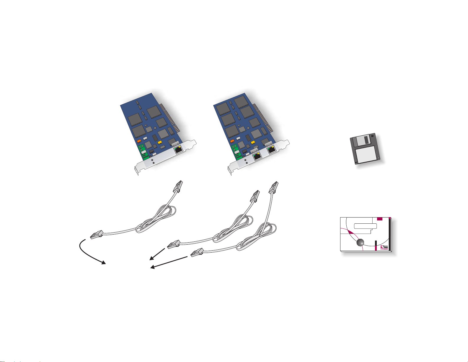
CHAPTER 1 WHAT IS IN THE BOX
Two Cyclades-PC400 models are available: one with DSPs (for analog modem connections) and one without
them (for digital connections). One cable per channel is provided for connection of the board to a T1/E1 line. A
diskette containing the PC400 driver is also included, and its use is described in chapter 3.
PC400 with
2 Channels
PC400
Driver
PC400 with
1 Channel
RJ-48C
RJ-48C
PC400 Driver
Diskette
RJ-48C
RJ-48C
//////////
RJ-48C
To T1 or E1
Connection
RJ-48C
Installation Manual
Upgrades of Software and Manuals
This product is provided with a printed Installation Manual. Both the manual and the driver are updated
frequently, and the latest versions can be downloaded free from the Cyclades Web site.
5Chapter 1 What is in the Box
Page 6

CHAPTER 2 HARDWARE INSTALLATION
The body carries static electricity and if the person installing the PC400 is not correctly grounded, the board
could suffer irreversible damage. Please follow the instructions outlined below carefully to avoid harming the
board.
Step One:
Unplug the computer and remove all cables connecting the computer to other devices.
Step Two:
Carry the computer to a workbench or table where an anti-static wrist-strap is available. It is highly
recommended that a wrist-strap be used. Remove the computer cover, exposing the boards inside. Attach the
wrist-strap to your wrist.
.
6Chapter 2 Hardware Installation
Page 7
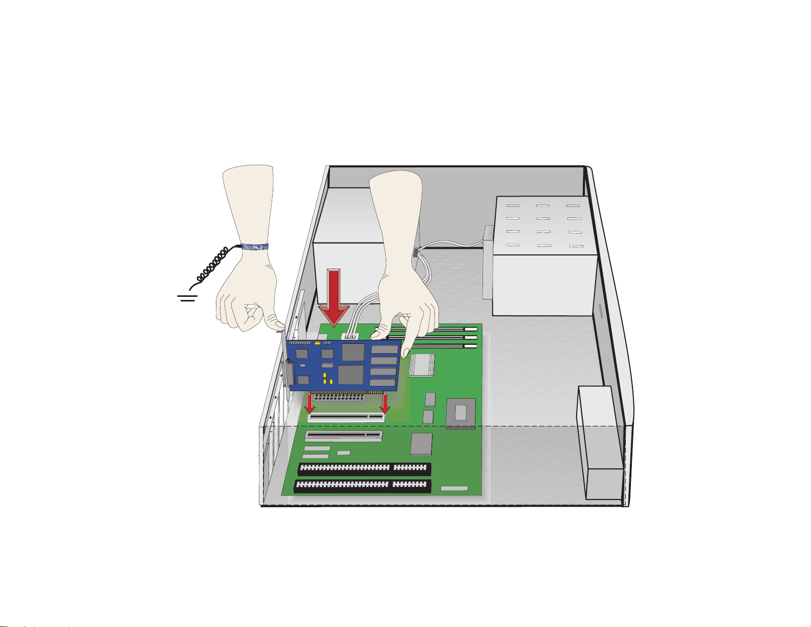
Step Three:
Be careful to not touch any components inside the computer’s chassis, as they also can be damaged by static
electricity. Confirm that the wrist-strap is grounded. If a wrist-strap is not available, touch a non-painted,
metallic part of a computer plugged in to a wall outlet to remove any excess charge. Remove the board from its
anti-static packaging, being careful to not touch the components or metal parts of the board.
.
7Chapter 2 Hardware Installation
Page 8
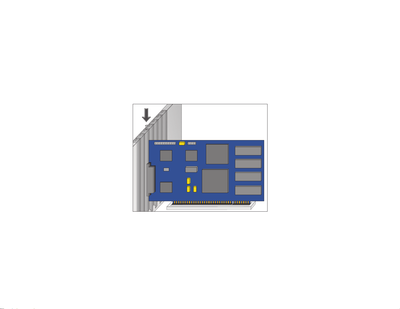
Step Four:
Insert the board carefully into any unused PCI slot so that the external connector is aligned with the opening in
the back of the computer. Make sure that the board does not touch any metallic parts of the interior of the
computer. The second bracket of models with two ports should be installed similarly.
Step Five:
Fasten the bracket to the back panel of the computer with a screw. Replace the computer’s cover and replace
the screws. Now you can remove the wrist-strap.
8Chapter 2 Hardware Installation
Page 9
CHAPTER 3 SOFTWARE INSTALLATION
The PC400 driver diskette contains the files needed to run the Cyclades-PC400 in a Linux environment. This
driver should run without problems with all processors supported by Linux. However, Ix86-compatible
architectures are the only platforms officially supported by Cyclades.
This Installation manual assumes a minimum knowledge of the Linux operating system. Please
read the file
/usr/src/linux/README
before continuing, in order to understand the basics of kernel
compilation.
System Requirements for compatibility with the PC400:
• Linux kernel 2.2.17 or later or 2.4.0 or later.
• 486 processor or better.
• PCI bus support.
These instructions assume that your kernel source tree is /usr/src/linux.
Before installing the driver, please back up any critical information in your system.
Log in to the Linux computer as root. Place the diskette in the diskette drive.
Execute the following commands, beginning from any directory:
cd /tmp
tar xvf /dev/fd0 (this command copies the tar file from the diskette to the directory /tmp )
ls (to see the name of the tar file)
tar zxvf filename.tgz (to unzip and untar the file)
ls (to see the name of the directory)
cd pc400-<version> (to go to the newly created directory)
9Chapter 3 Software Installation
Page 10

NOTE: at this point you should read the file README included in the directory pc400-<version>
to learn about any changes implemented since this manual was produced.
sh install (to run the install script)
This script will detect the system information (kernel version, current Cyclades-PC400 driver version, etc.) and
install the proper driver package files. A default configuration file will be placed in /etc/cyclades/pc400/
pc400.cfg and is used when /usr/local/sbin/pc400util -p is executed.The following utilities are compiled and
installed :
/usr/local/sbin/pc400util
/usr/local/sbin/pc400load
/usr/local/sbin/pc400dump
/usr/local/sbin/pc400hwtest
/usr/local/sbin/pc400syslog
And the firmware is installed in
/usr/local/lib/pc400.bin
If an older version of the PC400 driver already exists, the files pc400.c and pc400.h are backed up with
modified names in the same directory. If a newer version is already installed, the files will not be updated with
those of the older driver.
Configure the kernel by executing “make config” or “make menuconfig”:
Please note the following before beginning the kernel configuration. The only difference between
selecting ‘Y’ , ‘∗’ or ‘M’ is the following: ‘Y’ or ‘∗’ causes the driver to be compiled as part of the
kernel and is activated every time the computer is booted; ‘M’ creates the driver as a module, which
can be loaded or unloaded with a command without the need to reboot the computer.
10Chapter 3 Software Installation
Page 11
The left column presents the commands and parameters that should be followed when using make config.
The right column provides the corresponding commands and parameters for make menuconfig.
cd /usr/src/linux cd /usr/src/linux
make config make menuconfig
CONFIG_K MOD=Y (Kernel module lo ad er )
Activates support for module autoloading
Select with ‘∗’ or ‘M’ the option “Digital RAS Support” in the
“Character Devices” section, then select with ‘∗’ or ’M’ the
option “Cycla des-PC400 suppo rt” .
CONFIG_PCI=Y (PCI support)
CONFIG_DIGITAL_RAS=Y or M
Select with ‘∗’ the option “Kernel module loader” in the section
“Loadable module support .
(Digital RAS Support)
CONFIG_PC400=Y or M
After leaving “make config” or “make menuconfig”, execute the command
make dep
to set up the dependencies.
Rebuild and install the new kernel using the method most appropriate to the distribution being used. For
example, in most Linux distributions the default Linux kernel is placed in /vmlinuz and then loaded from there.
For these distributions, build the kernel by executing the command:
make bzlilo
If the PC400 driver or any other part of the Linux system was compiled as a module (M above),
execute the command
make bzlilo modules modules_install
instead of just
make bzlilo
The installation of the Cyclades-PC400 is continued in the next chapter.
11Chapter 3 Software Installation
Page 12
CHAPTER 4 BOARD AND SYSTEM CONFIGURATION
This chapter describes the configuration of the Cyclades-PC400. After the general instructions, guided examples are provided to assist in parameter selection. Read the example closest to your application if in doubt
as to the best value for a parameter.
STEP ONE
If the PC400 driver was compiled as a module and it is desired that the driver be autoloaded when a PC400
device is accessed, add the lines below to /etc/conf.modules (or /etc/modules.conf, depending on
the Linux distribution used):
alias char-major-214 pc400
alias char-major-215 pc400
IMPORTANT: the Cyclades-PC400 driver must be loaded before the device is used.
STEP TWO
Next, create a text file to store configuration variables or edit the default configuration file, /etc/cyclades/pc400/
pc400.cfg.. Only one label and one value per line, with a space between the label and the value. Blank lines
are allowed. Examples are shown later in this chapter. The parameters are grouped into blocks and applied to
each interface/channel/logical link/profile as will be seen below.
• General parameters define the user interface, name and password, together with some general options.
• ISDN-PRI profile parameters set trunk information such as telephone numbers and connection type for
up to five profiles.
• DSP profile parameters set the string to be sent to the SAP for up to five profiles.
12Chapter 4 Board and System Configuration
Page 13

• Interface parameters set T1/E1-line specific parameters such as clock mode and signalling type.
• Channel parameters define groups of channels (time slots) within a T1/E1 line.
• Logical link parameters set link information such as telephone number and connection type.
All parameters are presented below with a brief description of each. The basic structure of the file is as follows:
general parameters
cnx_profile_begin
Parameters that define this customized ISDN-PRI profile
cnx_profile_end
...
cnx_profile_begin
Parameters that define this customized ISDN-PRI profile
cnx_profile_end
dsp_profile_begin
Parameters that define and apply to this DSP profile
dsp_profile_end
...
dsp_profile_begin
Parameters that define and apply to this DSP profile
dsp_profile_end
interf1_begin
Parameters that configure T1/E1 Interface 1
channel_group_begin
Parameters that define and apply to this channel (time slot)
channel_group_end
...
channel_group_begin
Parameters that define and apply to this channel (time slot)
channel_group_end
interfn_1_begin
13Chapter 4 Board and System Configuration
Page 14

Parameters that define and apply to this logical link
interfn_1_end
...
interfn_N_begin
Parameters that define and apply to this logical link
interf1_N_end
interf1_end
interf2_begin
Parameters that configure T1/E1 Interface 2, when present
channel_group_begin
Parameters that define and apply to this channel (time slot)
channel_group_end
...
channel_group_begin
Parameters that define and apply to this channel (time slot)
channel_group_end
interfn_1_begin
Parameters that define and apply to this logical link
interfn_1_end
...
interfn_N_begin
Parameters that define and apply to this logical link
interfn_N_end
interf2_end
14Chapter 4 Board and System Configuration
Page 15

Label Description
unit_name Identifies the board. The parameter should not exceed 20 characters.
prompt Specifies the prompt to be used by the virtual console. It should not exceed 40
characters.
escape_char Specifies the escape key to be used by the virtual console. It should not exceed one
character. If the value begins with 0x it is assumed to be in hexadecimal. The <ESC> key
has the value 0x1b.
shortcut_char Specifies the shortcut key to be used by the virtual console. It should not exceed one
character. If the value begins with 0x it is assumed to be in hexadecimal. The value 0x0
turns this feature off.
username Defines the administrator's login name -- maximum 19 characters.
password Sets the administrator's password -- maximum 19 characters.
syslog Enables the system log and determines which messages will be displayed. The possible
values for each of the three parameters are disabled or enabled (first parameter), line,
debug, user, system, modem or a combination of them using “|” (second parameter) and
sys, alert, critical, error, warning, normal, info or dbg (third parameter). A space
should appear between each of the three parameters, but not within a parameter.
dsps_auto_restart On occasion, the line requests that the DSP re-load its configuration. Sometimes the re-
load is not successful and the DSP must try many times. This parameter determines the
number of times the DSP may try to re-load its configuration. The values range from 0
(infinite number of retries) to 255.
FIG 4.1 GENERAL PARAMETERS
15Chapter 4 Board and System Configuration
Page 16

Parameters that define customized ISDN-PRI profiles.
Label Description
cnx_profile_begin Up to 5 different ranges for cnx_profile can be configured .
phone The first phone number of the range with this profile. It should not exceed 30 characters
and "none" specifies the null string.
size_range The number of phone numbers in the range with this profile. Values range from 1 to 255.
No label is equivalent to the value 0.
cnx_type Type of incoming call. Possible values are analog, digital, v110, v120 or a combination
of the four separated by the pipe, "|".
cnx_profile_end ends definition of customized ISDN-PRI profile.
FIG. 4.2 ISDN-PRI PROFILE PARAMETERS
Parameters that define and apply to DSP profiles.
Label Description
dsp_profile_begin Marks the beginning of a digital signal processor profile. All parameters following this
label apply only to this dsp profile until dsp_profile_end is reached.
profile_id A number between 1 and 5 which labels the dsp profile for later reference.
config_string Commands sent to the dsp. It should not exceed 80 characters.
dsp_profile_end Marks the end of the configuration parameters for a digital signal processor profile. See
comments for dsp_profile_begin above.
FIG. 4.3 DSP PROFILE PARAMETERS
16Chapter 4 Board and System Configuration
Page 17

Parameters that define and apply to interfaces.
Label Description
interf#_begin Marks the beginning of the parameters specific to the #th T1/E1 interface. All
parameters following this label apply only to this interface until interf#_end is reached.
clock_mode Specifies the clock source. Can be either master or slave.
line_code Type of coding used in the line. T1: b8zs or ami, E1: hdb3 or ami.
frame_mode How data is framed. T1: esf, d4 or jesf, E1: crc4, ncrc4.
line_build_out Attenuation on the line. Applies to T1 lines only and the possible values are 0db, -7.5db,
-15db, and -22.5db.
signaling_mode Specifies the signaling mode: pri, cas or none.
profile ras, full, fractional or channelized. This parameter pre-sets several other parameters.
Details are given later in this chapter.
rx_sensitivity Degree of sensitivity for reception. Values are shaul (short haul) and lhaul (long haul).
signaling_type Specifies the kind of signaling used when the CAS signaling mode is chosen. The
possibilities are r2analog, r2digital (for E1) and winks and loops (for T1).
companding_mode E1: alaw or none, T1: ulaw or none.
signaling_tone Applies only when the CAS signaling mode is chosen. The possible values are dtmf and
mfr1 (for T1) and dtmf, mfr2c, mfr2nc and mfr2sc (for E1).
country Specificies the location of the PC400 if CAS signaling mode is being used. The options
are usa, brazil, mexico, romania, india, and itu.
block_collect Valid only for CAS in Brazil. Indicates whether or not collect calls should be blocked.
The valid values are enabled and disabled.
FIG. 4.4 INTERFACE PARAMETERS
17Chapter 4 Board and System Configuration
Page 18

Label Description
onhook_timer Valid only for CAS in Brazil. Valid values are 20-255, in units of a fraction of a second.
When the PC400 answers an incoming call it waits for the period defined by
answer2_timer, then it hangs up. Next, it waits the period defined by onhook_timer and
reconnects. The line remains active if the call was not a collect call. This is necessary
because in Brazil a collect call is accepted by simply remaining on the line.
answer2_timer Valid only for CAS in Brazil. Specifies the time that should elapse before answering an
incoming call. Valid values are 15-255, in units of a fraction of a second. See
description of onhook_timer.
trunk_number
Principal phone number assigned to the ISDN trunk line. Use the value
none
for this
parameter if the incoming number should not be confirmed by the PC400. This is
recommended when the provider does not send the trunk line number in the incoming
call message.
The value should not exceed 30 characters.
switch_type Switch type when PRI signaling is used. au1 (for Australia), ets (for Europe ETSI), vn6
(for France), tr6 (for Germany), dms (for USA – NorTel DMS-100), 5ess (for USA – AT&T
Custom), ntt (for Japan), n_isdn2 (for USA – NI-2), hkt (for Hong Kong) and 4ess (for
USA – AT&T).
idle_timeout For PRI signaling mode, specifies the idle timeout, in minutes, to drop one call. The
value should not exceed 127 and 0 indicates no timeout.
t200 For PRI signaling mode, specifies the ISDN T200 parameter, which may not exceed 255.
n200 For PRI signaling mode, specifies the ISDN N200 parameter, which may not exceed 255.
t203 For PRI signaling mode, specifies the ISDN T203 parameter, which may not exceed 255.
interf#_end Marks the end of the configuration parameters for the first interface. See comments for
interf#_begin above.
FIG. 4.4 INTERFACE PARAMETERS (CONT.)
18Chapter 4 Board and System Configuration
Page 19

Parameters that define and apply to channels (time slots). These go inside interface markers.
channel_group_begin Marks the beginning of a group of channels. All parameters following this label apply
only to this channel group until channel_group_end is reached.
channels
The number of channels in this channel group is defined. The value can be first-
last or channel_number|channel_number|channel_number etc.
channel_group_end Marks the end of a group of channels. See comments for channel_group_begin above
FIG. 4.5 CHANNEL PARAMETERS
Parameters that define and apply to logical links. These go inside interface markers.
interfn_1_begin Marks the beginning of the parameters for logical link 1. PRI allows 23 (T1) or 30 (E1)
channels whereas CAS allows 24 (T1) or 30 (E1) channels.
connection_type Indicates whether channel will be used for dial-in, dial-out or both.
phone_num Phone number assigned to the channel. The maximum number of characters is 30.
dsp_profile_id Specifies the DSP profile to be used for analog calls. 5 profiles are possible.
interfn_1_end Marks the end of the parameters for logical link 1.
FIG 4.6 LOGICAL LINK PARAMETERS
The default values and sample configurations are described later in this chapter in the examples section.
The firmware should be loaded with the command:
pc400load
which will load the file in /usr/local/lib/pc400.bin.
This configuration file should be loaded into the board’s memory with the command:
pc400util -p
The options of this command are given in appendix A.
STEP THREE
Edit one of the rc files (e.g. /etc/rc.d/rc.local) to include a call to the PC400´s firmware loader and configuration utility (so that the firmware and current configuration are loaded on boot):
19Chapter 4 Board and System Configuration
Page 20

# PC400 Firmware Download
if [ -x /usr/local/sbin/pc400load ]; then
/usr/local/sbin/pc400load
fi
# PC400 Configuration Download
if [ -x /usr/local/sbin/pc400util ]; then
/usr/local/sbin/pc400util -p
fi
# PC400 Date and Time Set
if [ -x /usr/local/sbin/pc400util ]; then
/usr/local/sbin/pc400util -t system
fi
IMPORTANT: the Cyclades-PC400 driver must be loaded before the firmware and the configuration
are downloaded to the board. Thus, if you compiled the driver as a loadable module, make sure you
load the driver module before you call pc400load and pc400util.
If you use the rc files to load the module, for instance, do the following:
# PC400 Driver Load
if [ -x /sbin/modprobe ]; then
/sbin/modprobe pc400
fi
# PC400 Firmware Download
if [ -x /usr/local/sbin/pc400load ]; then
/usr/local/sbin/pc400load
fi
# PC400 Configuration Download
if [ -x /usr/local/sbin/pc400util ]; then
/usr/local/sbin/pc400util -p
fi
STEP FOUR
Reboot the system and inspect the boot messages. The driver should report the PC400 boards detected.
20Chapter 4 Board and System Configuration
Page 21

Cyclades-PC400 driver <version> <date> built <date>
PC400 #1, RAM at 0xMMMM, IRQn, 64 channels starting from port 0
PC400 #2, RAM at 0xMMMM, IRQn, 64 channels starting from port 64
etc.
STEP FIVE
Enable the ports of the Cyclades-PC400 as you would with any standard serial port. Edit /etc/inittab to enable
getty and configure the PPP/SLIP scripts.
The site www.netlinos.org (Documentation->Tutorials->Remote Access) has an example of how to set up a
digital RAS using the PC400 and the software package portslave.
At this point the installation of the board is complete.
Guided Examples for the Most Common Applications
This section provides detailed examples that can be used as models for similar applications. Turn to the example that is closest to your application, read the explanations, and edit the configuration file with parameters
appropriate to your system. Note that these examples only show the configuration of the first interface. The
configuration of the second interface is identical.
21Chapter 4 Board and System Configuration
Page 22

Example 1 A RAS Dial-in Application With Both Analog and Digital Incoming Calls
LAN
PC
Server
Server
with PC400
Multiple Calls
Modem
T1/E1
ISDN-BRI
Telephone/ISDN
Network
Remote
IP Address
Assigned on
Connection
Network
Terminator
Lines
Modem
PCPC
PC
PC
Network
Terminator
FIGURE 4.7 EXAMPLE OF A RAS DIAL-IN APPLICATION
Sample pc400.cfg files are provided on the driver diskette for the RAS dial-in application, in the directory
Config_Sample. If you have a T1 line, use the file 2t1cas.cfg as a reference, if your line is E1, use the file
2e1cas.cfg.
22Chapter 4 Board and System Configuration
Page 23

Parameter Description Value for T1
line
Value for E1
line
unit_name Name used to identify the board. PC400 PC400
prompt Can be changed to identify which board is being
accessed.
Select option
==>
Select option
==>
escape_char 0x1b is the <ESC> key. 0x1b 0x1b
shortcut_char 0x0 turns this feature off. 0x0 0x0
username Login name for administrator. super super
password Password for administrator supc supc
syslog Enables syslog messages indicated. enabled
line|debug|user|s
ystem|modem
info
enabled
line|debug|user|s
ystem|modem
info
interf1_begin First interface parameters
interf_type Indicates line time t1 e1
clock_mode Normally slave. slave slave
line_code There are two options each for T1 and E1 lines. Ask
b8zs hdb3
the service provider.
frame_mode There are several data framing options for both T1
esf crc4
and E1.
line_build_out Applies only to T1 lines. Ask the service provider. 0db
signaling_mode Can be pri (ISDN), cas or none. cas cas
FIGURE 4.8 RAS DIAL-IN APPLICATION PARAMETERS
23Chapter 4 Board and System Configuration
Page 24

Parameter Description Value for T1
line
Value for E1
line
rx_sensitivity Sensitivity for reception. shaul shaul
companding_mode There are two options each for T1 and E1 lines. Ask
ulaw alaw
the service provider.
signaling_type Applies when CAS signaling mode is used. Ask the
loops r2digital
service provider.
signaling_tone Applies when CAS signaling mode is used. Ask the
mfr1 mfr2c
service provider.
country Choose your country (cas only). usa brazil
interfn_1_begin Logical link parameters
connection_type Whether the interface will be used for dial-in, dial-out
both both
or both.
phone_num Phone number assigned to channel, if any. none 301
dsp_profile_id Number that identifies the profile, defined elsewhere
11
(or default)
interfn_1_end End of logical link parameters
•••
interf1_end End of first interface parameters
interf2_begin Second interface parameters
•••
interf2_end End of second interface parameters
dsps_auto_restart The number of times the DSP should try to re-load
its configuration if requested.
FIGURE 4.8 RAS DIAL-IN APPLICATION PARAMETERS (CONT.)
00
24Chapter 4 Board and System Configuration
Page 25

Example 2 A LAN-to-LAN Example Using Channels
Headquarters’
LAN
ETH0
Server
with PC400
T1/E1
Channels
11-15
Channels
1-10
Affiliate’s
LAN
PR1000
PR1000
Affiliate’s
LAN
FIGURE 4.9 EXAMPLE OF A MULTIPLE LAN-TO-LAN APPLICATION
The example shown above would be configured using the channelized profile. Sample pc400.cfg files are provided on the driver diskette for the LAN-to-LAN application, in the directory Config_Sample. If you have a T1
line, use the file 2t1chan3.cfg as a reference, if your line is E1, use the file 2e1chan3.cfg.
25Chapter 4 Board and System Configuration
Page 26

Parameter Description Value for T1
line
Value for E1
line
unit_name Name used to identify the board. PC400 PC400
prompt Can be changed to identify which board is being
accessed.
Select option
==>
Select option
==>
escape_char 0x1b is the <ESC> key. 0x1b 0x1b
shortcut_char 0x0 turns this feature off. 0x0 0x0
username Login name for administrator. super super
password Password for administrator supc supc
syslog Enables syslog messages indicated. enabled
line|debug|user|s
ystem|modem
info
enabled
line|debug|user|s
ystem|modem
info
interf1_begin First interface parameters
interf_type Indicates line time t1 e1
clock_mode Normally master. master slave
line_code There are two options each for T1 and E1 lines.
b8zs hdb3
Ask the service provider.
frame_mode There are several data framing options for both
esf crc4
T1 and E1.
line_build_out Applies only to T1 lines. Ask the service
0db
provider.
signaling_mode Can be pri (ISDN), cas or none. none none
FIGURE 4.10 MULTIPLE LAN-TO-LAN APPLICATION PARAMETERS
26Chapter 4 Board and System Configuration
Page 27

Parameter Description Value for T1
line
Value for E1
line
rx_sensitivity Sensitivity for reception. shaul shaul
channel_group_begin Definition of first channel group.
channels Channels in first group. 1-10 1-10
channel_group_end End of definition of first channel group.
channel_group_begin Definition of second channel group.
channels Channels in second group. 11-15 11-20
channel_group_end End of definition of second channel group.
•••
interf1_end End of first interface parameters
interf2_begin Second interface parameters
•••
interf2_end End of second interface parameters
dsps_auto_restart The number of times the DSP should try to re-
00
load its configuration if requested.
FIGURE 4.10 MULTIPLE LAN-TO-LAN APPLICATION PARAMETERS (CONT.)
27Chapter 4 Board and System Configuration
Page 28

Cyclades-PC400 Installation Manual
CHAPTER 5 TROUBLESHOOTING
General Tips
What to Do When the PC400 is Not Recognized by the Operating System
• Does the operating system detect the PC400 on boot? A message similar to
Cyclades-PC400 driver <version> <date> built <date>
PC400 #1, RAM at 0xMMMM, IRQn, 64 channels starting from port 0
PC400 #2, RAM at 0xMMMM, IRQn, 64 channels starting from port 64
etc.
should appear on boot. If not,
• Is the board properly installed (physically)? Check the connections inside the computer.
• Does your Linux operating system meet the requirements outlined at the beginning of chapter 3? The
kernel version can be discovered by typing the command uname
-r.
• The steps in chapter 4 related to the device files should be reviewed and the configuration files checked.
• Check the configurations modified using “make config” or “make menuconfig” (details supplied in chapter
3). If they are incorrect, execute the commands make dep and then make bzlilo modules
modules_install again to rebuild the kernel. Reboot the computer and see if the boards are detected.
How to Test if the PC400 is Functioning
• The simplest way to test a WAN connection is by pinging. Type ping <IP address of device to be
pinged>. If a response is not received from the remote machine there is probably a problem with the link.
Make sure the remote machine is up by accessing it from another computer before following the directions
below.
What to Do if the PC400 is Detected by the Computer, but Does Not Function as Expected.
• Is the cable properly connected and is the correct cable being used?
• Type the command ifconfig. Do the devices set up for the board in chapter 4 appear?
• Type the command netstat -rn to see the routing table. Have you defined a default gateway and/or have
a route that includes the remote device you are trying to reach?
Chapter 5 Troubleshooting 28
Page 29

Cyclades-PC400 Installation Manual
Hardware Test
A menu-driven hardware test called pc400hwtest is included with the Cyclades-PC400 driver. It is executed by
typing pc400hwtest at the command line. Note that the PC400 should not be tested while in use as the test will
inactivate all ports. First, RAM integrity is checked:
[root@cyclades common]# ./pc400hwtest
Please wait while program is examining the hardware
BOARD[1] RAM TEST ED000000, PCI ED926000 OK !
Press [enter] to continue.
Application Checking Firmware Integrity (CRC) ... OK
Then press the <ENTER> key to bring up the main screen, shown below:
PC400HWTest/Linux
Revision 2.0.0 (2001/12/12)
1. Test Asynchronous Ports
2. Test T1 Channelized Ports
3. Test E1 DSP Ports
4. Quit
Select option ==>
29Chapter 5 Troubleshooting
Page 30

Cyclades-PC400 Installation Manual
After choosing one of the first three options, the “global” screen appears as shown below:
Global Test DSP Passes - 1741 Pg0.
Board RAM FALC : 01 02 DSP : U19 U06 U20 U07
-------------------------------------------------- 1 OK OK OK OK N/T NOK NOK
<ESC> - Previous Menu <G> - Global <E> - Errors
Typing E will bring up the “errors” screen as shown below:
Chapter 5 Troubleshooting 30
Page 31

Cyclades-PC400 Installation Manual
Board Port <---- PACKETS ---> Test : DSP
From To From To Sent Received Passes Errors Pg0
-------------------------------------------------------------- 1 <-> 1 1 <-> 33 1741 1741 1741 0
1 <-> 1 2 <-> 34 1741 1741 1741 0
1 <-> 1 3 <-> 35 1741 1741 1741 0
1 <-> 1 4 <-> 36 1741 1741 1741 0
1 <-> 1 5 <-> 37 1741 1741 1741 0
1 <-> 1 6 <-> 38 1741 1741 1741 0
1 <-> 1 7 <-> 39 1741 1741 1741 0
1 <-> 1 8 <-> 40 1741 1741 1741 0
1 <-> 1 9 <-> 41 1741 1741 1741 0
1 <-> 1 10 <-> 42 1741 1741 1741 0
1 <-> 1 11 <-> 43 1741 1741 1741 0
1 <-> 1 33 <-> 1 1741 1741 1741 0
1 <-> 1 34 <-> 2 1741 1741 1741 0
1 <-> 1 35 <-> 3 1741 1741 1741 0
1 <-> 1 36 <-> 4 1741 1741 1741 0
1 <-> 1 37 <-> 5 1741 1741 1741 0
1 <-> 1 38 <-> 6 1741 1741 1741 0
1 <-> 1 39 <-> 7 1741 1741 1741 0
1 <-> 1 40 <-> 8 1741 1741 1741 0
<ESC> - Previous Menu <G> - Global <E> - Errors
Typing G or E switches between the two screens and the ESC key returns to the main menu. The “+” serves to
scroll down and “-” scrolls up.
31Chapter 5 Troubleshooting
Page 32

Cyclades-PC400 Installation Manual
Administrative Utilities
A program called pc400util is used for administrative functions. It is executed by typing pc400util at the command
line with the following options:
pc400util -<g|p|s|S|i|-a<up|down>> [-d device] [-f <file|default>] [-t <MMDDYYYYHHMMSS|system>]
The options are described in more detail in the list below:
-d device defines the configuration device to use.
-f file defines the file to be up/downloaded
-g upload current board configuration to a local file.
-p download configuration from a local file to the
board.
-s get current statistics.
-S get current status.
-i get board information.
-a cmd set the device administrative up or down.
-t time set date and time on the board.
Chapter 5 Troubleshooting 32
Page 33

Cyclades-PC400
Installation Manual
APPENDIX A INFORMATION FOR USERS NOT FAMILIAR WITH LINUX
Users and Passwords
A username and password are necessary to log in to a Linux system. A unique password should be configured
as soon as possible to avoid unauthorized access to your network.
Type the command:
passwd
to create a password for the root user.
To create a regular user (without root privileges), use the commands:
adduser
passwd
user_name
user_password
Linux File Structure
The Linux file system is organized hierarchically, with the base (or root) directory represented by the symbol “/”.
All folders and files are nested within each other below this base directory. The directories located just below
the base directory are:
Appendix A - Linux
33
Page 34

Cyclades-PC400
Installation Manual
/home Contains the work directories of system users.
/bin Contains applications and utilities used during system initialization.
/dev Contains files for devices and ports.
/etc Contains configuration files specific to the operating system.
/lib Contains shared libra ries.
/proc Contains process information
/mnt Contains information about mounted disks.
/opt Location where packages not supplied with the operating system are stored.
/tmp Location where temporary files are stored.
/usr Contains most of the operating system files.
/var Contains operating system data files.
Basic File Manipulation Commands
The basic file manipulation commands allow the user to copy, delete and move files and create and delete
directories.
cp
file_name destination
a) cp text.txt /tmp
b) cp /chap/robo.php ./excess.php
rm
file_name
mv
file_name destination
mkdir
directory_name
a) mkdir spot
b) mkdir /tmp/snuggles
rmdir
Appendix A - Linux
directory_name
Copies the file indicated by
destination
. a) copies the file text.txt in the current directory to the tmp
file_name
to the path indicated by
directory. b) copies the file robo.php in the chap directory to the
current directory and renames the copy excess.php.
Removes the file indicated by
Moves the file indicated by
file_name
file_name
.
to the path indicated by
destination.
Creates a directory named directory_name. a) creates the directory
spot in the current directory. b) creates the directory snuggles in the
directory tmp.
Removes the directory indicated by
directory_name
.
34
Page 35

Cyclades-PC400
Installation Manual
Other commands allow the user to change directories and see the contents of a directory.
pwd Supplies the name of the current directory. While logged in, the user is always
"in" a directory. The default initial directory is the user's home directory,
/home/<username>
ls [options]
directory_name
Lists the files and directories within
directory_name
. Some useful options are -l
for more detailed output and -a which shows hidden system files.
cd
directory_name
cat
file_name
Changes the directory to the one specified
Prints the contents of
file_name
to the screen.
Shortcuts:
. (a dot) represents the current directory
.. (two dots) represents one directory above the current directory (i.e. one directory closer to the base
directory).
The vi Editor
To edit a file using the vi editor, type
vi file_name
vi is a three-state line editor: it has a command mode, a line mode and an editing mode. If in doubt as to which
mode you are in, press the <ESC> key which will bring you to the command mode.
Mode What is done there How to Get There
command mode navigation within the open file Press the <ESC> key.
editing mode text editing See list of editing commands below.
line mode file saving, opening, etc. exiting
from vi
From the command mode, type ":" (the
colon).
Entering the program, the user is automatically in the command mode. To navigate to the part of the file to be
Appendix A - Linux
35
Page 36

Cyclades-PC400
edited, use the following keys:
Installation Manual
h
j
k
l
moves the cursor to the left (left arrow)
moves the cursor to the next line (down arrow)
moves the cursor to the previous line (up arrow)
moves the cursor to the right (right arrow)
Having arrived at the location where text should be changed, use these commands to modify the text (note
commands “i” and “o” will move you into the editing mode and everything typed will be taken literally until you
press the <ESC> key to return to the command mode)
i
insert text before the cursor position (everything to
the right of the cursor is shifted right)
o
create a new line below the current line and insert
text (all lines are shifted down)
dd
u
x
remove the entire current line
undo the last modification
delete the letter at the cursor position
Now that the file has been modified, enter the line mode (by typing “:” from the command mode) and use one of
the following commands:
w
wq
q!
w
e
file
file
save the file (w is for write)
save and close the file (q is for quit)
close the file without saving
save the file with the name
opens the file named
file
file
The Routing Table
The static routing table can be seen using the commands
route -n
or
Appendix A - Linux
36
Page 37

Cyclades-PC400
Installation Manual
netstat -rn
Type man netstat at the Linux prompt for more informations about netstat options. Routes should be added to
the file /proc/net/route or at the prompt (for temporary routes) using the following syntax:
route [add|del] [-net|-host]
[add|del]
[-net|-host]
target
netmask
nt_msk
gt_way
gw
target
one of these tags must be present -- routes can be either added or deleted.
-net is for routes to a network and -host is for routes to a single host.
target
is the IP address of the destination host or network
the tag netmask and a mask are necessary only when subnetting is used. Otherwise, a
mask appropriate to the
target
specifies a gateway, when applicable.
netmask
is assumed.
gt_way
nt_msk
nt_msk
[gw
gt_way] interf
must be specified in dot notation.
is the IP address or hostname of the
gateway.
interf
the interface to use for this route. Must be specified if a gateway is not. When a gateway
is specified, the operating system determines which interface is to be used.
Type man route at the Linux prompt for more information about the syntax for the command route.
ssh - The Secure Shell Session
ssh is a command interface and protocol often used by network administrators to connect securely to a remote
computer, and is a highly recommended alternative to telnet/rlogin. ssh replaces its non-secure counterpart rsh.
There are two versions of the protocol, ssh and ssh2. Type man ssh2 at the Linux command prompt for more
information about the use of ssh.
Appendix A - Linux
37
Page 38

Cyclades-PC400
Installation Manual
The Process Table
The process table shows which processes are running and is displayed by tying ps -a. An example is given
below.
PID TTY STAT TIME COMMAND
1 ? S 0:05 init
322 ? SW 0:00 [portmap]
3361 tty11 SW 0:00 [login]
11915 pts/0 S 0:00 bash
11926 pts/0 R 0:00 ps -ax
Use the kill command to delete a process. For example, kill -9 3361 would kill the login process above.
Loading the Configuration File
This configuration file (for non-default configurations) should be loaded into the board´s memory with the command:
pc400util -p -f <text file>
The options of this command are:
pr400util -<g|p|s|S|i|-a<up|down>> [-d device] [-f <file|default>] [-t <MMDDYYYYHHMMSS|system>]
where
-d device defines the configuration device to be used. The possible values are /dev/ttyCM0 to /dev/
ttyCM31 where /dev/ttyCM31 is a virtual console than can be accessed using Minicom
or a similar utility .
-f file use <file> as the file argument, <default> accepts the default parameters.
-g upload current board config. to a local file.
-p download config. from a local file to the board.
-s get current statistics.
-S get current status.
-a cmd set the device Adm UP or Down.
-t time set date and time on the board
Appendix A - Linux
38
Page 39

Cyclades-PC400
Installation Manual
-i get information from the board
Syslog
The syslog feature can be turned on, as an option. It runs in background, by default. Its syntax is:
pc400syslog [-d device] [-l facility]
-d device : defines the syslog device (the default is /dev/ttyCM30)
-l <facility> : where <facility> is a number between 0 and 7, indicates the local_level
it sends Syslog messages generated by the PC400 firmware to the Syslogd running on the Linux server. It can
also be initialized using the rc.local file described later.
The Crond Utility
A list of Linux shell commands can be saved in a "crontab" file and executed at a specific time. The crontab
command provides a user interface to change the crontab file. To use crond, first create the following two files
for every process that it will execute:
1. crontab - the file that specifies frequency of execution, name of shell script, etc. should be created using the
traditional crontab file format.
2. script shell - a script file with the Linux commands to be executed.
Each line of the crontab file has five time and date fields, followed by a user name if it is the system crontab file,
followed by a command.
minute hour date month day-of-week [user] command
Commands are executed when the minute, hour and month fields match the current time and when at least one
of the two day fields (day of month or day of week) match the current time. An * represents the entire possible
range of values (e.g. every day or every month).
Next, create a line in the file /etc/crontab_files for each process to be run.
Each line must contain the three items:
Appendix A - Linux
39
Page 40

Cyclades-PC400
• status (active or inactive) - if this item is not active, the script will not be executed.
• user - the process will be run with the privileges of this user, who must be a valid local user.
• source - pathname of the crontab file.
Installation Manual
When the /etc/crontab_files file contains the following line:
active root /etc/tst_cron.src
and the /etc/tst_cron.src file contains the following line:
0-59 * * * * /etc/test_cron.sh
crond will execute the script listed in tst_cron.sh with root privileges each minute.
Another option is to use the crontab command to interactively modify the crontab file. Its syntax is:
crontab [-u user] file or crontab [-u user] { -e | -l | -r }
where
-e = edit user’s crontab
-l = list user’s crontab
-r = delete user’s crontab
Type man cron and man crontab at the Linux prompt for more information.
The DHCP (Dynamic Host Configuration Protocol) Client
DHCP is a protocol that allows network administrators to assign IP addresses automatically to network devices.
Without DHCP (or a similar protocol like BOOTP), each device would have to configured manually. DHCP
automatically sends a new IP address to a connected device when it is moved to another location on the
network. DHCP uses the concept of a fixed time period during which the assigned IP address is valid for the
device it was assigned for. This “lease” time can vary for each device. A short lease time can be used when
there are more devices than available IP numbers. For more information on how to set your server up as a
DHCP client or server, see RFC 2131 or the DHCP pages at www.linuxdoc.org
Appendix A - Linux
40
Page 41

Cyclades-PC400
Installation Manual
Packet Filtering using ipchains
The Linux utility ipchains can be used to filter IP packets entering, leaving and passing through interfaces. An
ipchains tutorial is beyond the scope of this manual. For more information on ipchains, see the ipchains man
page (by typing man ipchains at the Linux command prompt) or the howto: http://netfilter.filewatcher.org/ipchains/
HOWTO.html.
The syntax of the ipchains command is:
ipchains -
target
] [-i
command chain
interface
]
[-s
source
] [-d
destination
] [-p
protocol
] [-j
where command is one of the following:
A - Add a condition or rule to the end of the chain. Note that the order in which a condition appears in a chain
can modify its application and the first rule added to a chain is processed first, etc.
D - Delete a condition from the chain. The condition must match exactly with the command’s arguments to be
deleted.
R- Replace a condition in the chain.
I - Insert a condition in a specified location in the chain.
L - List all conditions in the chain.
F - Flush (remove) all conditions in the chain.
N - Create a new chain.
X - Deletes a user-created chain
P - Policy applied for default handling
chain is one of the following:
input - filters incoming packets
output - filters outgoing packets
forward - filters packets which are not created by the server and are not destined to the server
user_created_chain
- a previously defined (or in the process of being defined) chain created using the N
command described above.
Appendix A - Linux
41
Page 42

Cyclades-PC400
Installation Manual
The output chain controls which packets are sent. A packet can be accepted by the input chain, but then rejected
by the output chain. Likewise, the forward chain controls which packets will be routed. The input chain controls
incoming packet filtering. The packet is either destined for the router or for another computer. In the latter case,
the packet is processed by the forward chain. Packets that pass through the forward chain will then be processed by the output chain.
source and destination have the following format:
address[/mask
[!]
] [!][
port[:port
]]
! : reverses the definition, resulting in the opposite effect.
address : host or network IP
port : defines a specific port
port:port : defines a range of ports
If a source or destination is not specified then 0.0.0.0/0 is used.
protocol is one of the following:
tcp, udp, icmp, all or a protocol number (see the file /etc/protocols for a list).
target is one of the following:
ACCEPT
DENY
the name of another chain
interface is:
one of the server interfaces. Lists do not need to be associated to an interface, so this option may be omitted.
To save changes made using the ipchains command, execute fwset. This command will save the filter configuration in the file /etc/network/firewall.
To delete the changes made (before fwset is executed) execute fwset restore to return to the lists previously
saved in /etc/network/firewall. Only the lists previously saved using fwset will then be defined. This command is
Appendix A - Linux
42
Page 43

Cyclades-PC400
Installation Manual
executed at boot to invoke the last configuration saved.
Another option is to edit the file /etc/network/firewall (or another file) directly, following the syntax defined in the
file itself. If the file is edited in this way, the command fwset cannot be used to save and restore the configuration. Use
ipchains-save > file_name to save the lists in file_name
updatefiles file_name to save file_name to flash memory
ipchains-restore < file_name to restore the lists to the configuration in file_name
Appendix A - Linux
43
Page 44

Cyclades-PC400
Installation Manual
APPENDIX B HARDWARE SPECIFICATIONS
This chapter provides the pinout diagram for the cable supplied with the product, in case it is lost or damaged.
Cyclades-PC400
RJ-48C
Signal
Pin
RxTip
RxRing
N.C.
TxTip
TxRing
N.C.
N.C.
N.C.
T1/E1 Terminal Adapter
RJ-48C
Pin
1
2
3
4
5
6
7
8
1
2
3
4
5
6
7
8
Signal
RxTip
RxRing
N.C.
TxTip
TxRing
N.C.
N.C.
N.C.
Appendix B - Hardware Specifications
44
Page 45

Cyclades Australia
20 Arrabri A ve
Jindalee - Qld, 4074 Australia
Phone: +61 7 3279 4320
Fax: +61 7 3279 4393
www .au.cyclades.com
Cyclades Corporation
41829 Albrae Street
Fremont, CA 94538 - USA
Phone: (510) 770-9727
Fax: (510) 770-0355
www .cyclades.com
Cyclades South America
Av. Santa Catarina, 155
04635-000 São Paulo, SP, Brazil
Phone: 55-11-5033-3333
Fax: 55-11-5033-3388
www .cyclades.com.br
Cyclades Philippines
Unit 804, LT A Bldg. 118 Perea St.
Legaspi V illage
Makati City Phillipines 1200
Phone: (632) 813-0353
Fax: (632) 655-2610
www .ph.cyclades.com
Cyclades UK
Unit 6 Moorwell Road Business Park
Scunthorpe, North Lincolnhire DN17 2RU - UK
Phone: +44 1724 277179
Fax: +44 1724 279981
www .uk.cyclades.com
Cyclades Germany
Rennweg 33
85435 Erding - Germany
Phone: +49 (0)81 22 90 99-90
Fax: +49 (0)81 22 90 999-33
www .cyclades.de
 Loading...