

Page 1

AlterPath BladeManager
User Manual
Product Version 1.3.0
Revision No. 7
This document contains proprietary information of Cyclades and is not to be disclosed
or used except in accordance with applicable contracts or agreements.
©
Cyclades Corporation, 2005
Page 2

We believe the information in this manual is accurate and reliable. However, we assume no
responsibility, financial or otherwise, for any consequences of the use of this product or manual.
This manual is published by Cyclades Corporation, which reserves the right to make improvements
or changes in the products described in this manual as well as to revise this publication at any time
and without notice to any person of such revision or change. All brand and product names
mentioned in this publication are trademarks or registered trademarks of their respective holders.
Cyclades, AlterPath ACS, AlterPath KVM/net, AlterPath Manager E2000, and AlterPath
BladeManager are registered trademarks of Cyclades Corporation.
IBM, IBM BladeCenter and ServeRAID are registered trademarks of IBM Corporation.
Microsoft, Windows 95, 98, XP, ME, NT, and 2K are trademarks of Microsoft Corporation.
UNIX is a trademark of UNIX System Laboratories, Inc.
Linux is a registered trademark of Linus Torvalds.
For latest manual revisions, please refer to Cyclades website on:
http://www.cyclades.com/support/downloads.php
All rights reserved. This document may not, in whole or part, be copied, photocopied, reproduced,
translated, or converted to any electronic or machine-readable form without the prior written
consent of Cyclades Corporation, 3541 Gateway Boulevard, Fremont, CA 94538, USA.
Telephone (510) 771-6100. Fax (510) 771-6200. www.cyclades.com.
Page 3

Table of Contents
Before You Begin
Audience i
Document Organization i
Typographical Conventions ii
Naming Conventions ii
Chapter 1: Introduction
Connectivity and Capacity 1-2
Key Features 1-2
Single Point Security Gateway 1-3
Centralized Authentication 1-3
Consolidated Views and Blade Access 1-3
Simple and Easy Web User Interface 1-3
One-Click Access to Blades and Switches 1-4
Centralized Data Logging System 1-4
Log File Compression and Rotation 1-4
Prioritized Triggers & Alarms 1-4
Other Alarm Features 1-5
Blade Wizard 1-5
Chassis, Blades, and User Group
Management 1-5
Backup, Restore, and Replicate User Data 1-5
Exhaustive Reporting 1-6
Multiport Ethernet Cards 1-6
Command Line Interface (CLI) 1-6
Deploying the BladeManager 1-7
Chapter 2: BladeManager Installation
Product Installation Checklist 2-1
Rack Mounting Guidelines 2-2
Major Components of the BladeManager 2-11
AlterPath Blade Manager Manual
Page 4

Table of Contents
Installation Safety Guidelines 2-12
System Reliability Guidelines 2-12
Static-Sensitive Devices 2-12
Installation Procedures 2-13
Installing DIMMs 2-13
Installing a Hard Disk Drive 2-15
Installing a Simple-Swap Serial
ATA Hard Disk Drive 2-15
Installing a SCSI Hard Drive 2-16
Installing an Adapter 2-17
Completing the Installation 2-21
Connecting the Cables 2-22
Updating the Server Configuration 2-23
BladeManager Controls, LEDs, and Power 2-23
BladeManager Power Features 2-26
Switching On the Server 2-26
Switching Off the BladeManager 2-27
Pre-Configuration Requirements 2-28
Configuring the COM Port Connection
and Logging In 2-29
Chapter 3: BladeManager Web Access
User Interface Overview 3-1
Using the Web Interface as a Regular User 3-2
General Screen Features 3-4
Sorting a List Form by Column/Field Name 3-4
Search and Filter Functions 3-5
Alarms 3-5
Alarm Logs 3-6
Responding to an alarm 3-6
Alarm List Form 3-6
Viewing the Alarm Detail Form 3-8
Viewing Alarm or Console Logs 3-10
Assigning a Ticket to a User 3-10
II AlterPath BladeManager Manual
Page 5

Blades 3-11
Viewing the Blade List 3-11
Connecting to a Blade Console 3-13
Multiple Users and Read/Write Access 3-13
Viewing a Blade or Switch 3-14
Consoles Detail Form 3-14
Consoles Access Form 3-16
Consoles Notify Form 3-16
Consoles Groups Form 3-17
Logs 3-18
Viewing the Logs 3-19
Access Logs 3-20
Event Logs 3-21
Data Buffer 3-22
User’s Profile 3-23
Changing Your Password 3-25
Viewing the Use Access Form 3-25
Viewing the User Groups Form 3-25
Viewing the Security Form 3-27
Table of Contents
Chapter 4: BladeManager Web Administration
Operational Modes 4-2
Configuration Process Flow 4-3
First Time Configuration Wizard 4-4
Running the First Time Configuration
Wizard 4-4
Resetting Configuration to Factory Settings 4-5
First Time Configuration Wizard:
An Example 4-6
Setting the Authentication Method 4-8
Hostname Configuration Must
Follow RFC Standard 4-8
AlterPath BladeManager Manual III
Page 6

Table of Contents
Connecting to the Web Interface 4-9
BladeManager Web Interface: Admin Mode 4-10
Forms Summary 4-10
Logging Into the BladeManager Web Interface 4-14
Parts of the Web Interface 4-14
Sorting, Filtering, and Saving a List Form 4-16
Using the Form Input Fields 4-17
Verifying Error Messages 4-17
Chassis Management 4-17
Chassis > Devices List Form 4-19
Using a DHCP Server and Selecting the
Correct IP Mode 4-24
Function of the Status Field 4-24
Selecting the Group(s) to Access a Chassis 4-25
Proxies 4-26
Proxy Types 4-26
Configuring the Proxy 4-28
Verifying your Proxy Setting 4-29
Disabling the Proxy 4-29
Configuring Ports to be Proxied 4-29
Configuring the Chassis Switch 4-29
Two Methods of Blade Configuration 4-31
Running the Blade Wizard 4-32
Configuring Blades Manually
through the Menu 4-37
Consoles List Form 4-37
Connecting to a Device 4-38
Deleting a Device 4-38
Deleting a Device from a Group 4-39
Deleting a Device Group 4-39
Alarm Trigger 4-39
Alarm Trigger Management 4-40
IV AlterPath BladeManager Manual
Page 7

Viewing the Alarm Trigger List 4-40
Creating an Alarm Trigger 4-41
Deleting an Alarm Trigger 4-43
Using the Logical AND in the
Alarm Trigger Expression 4-43
Blades / Switches 4-43
Consoles List Form 4-44
Viewing the Console List 4-45
Adding a Serial Console 4-46
Adding a Switch Console 4-49
Selecting Users to Access the Console 4-49
Selecting Users to be Notified 4-50
Assigning the Console to a Group 4-51
Deleting a Console from a Group 4-52
Deleting a Console Group 4-53
Connecting to a Console 4-53
Log Rotation 4-53
Initiating Log Rotation 4-53
Setting Log Rotation in Auto Mode 4-54
Table of Contents
Users 4-54
User List form 4-55
Adding a User 4-55
Selecting Consoles for a User 4-58
Selecting User Group(s) for a User 4-59
Deleting a User 4-60
Deleting a User from a Group 4-60
Deleting a User Group 4-60
Setting the Local Password 4-61
Setting Up Local Authentication 4-61
Setting a User’s Security Profile 4-61
Groups 62
Creating a Group 4-62
Deleting a Group 4-64
AlterPath BladeManager Manual V
Page 8

Table of Contents
Assigning a Security Profile to a User Group 4-64
Security Profiles 4-65
Security Profile List 4-66
Adding or Editing a Security Profile 4-67
Security Profiles: Source IP 4-68
Security Profiles: LAN ITF 4-70
Security Profile: Date/Time 4-72
Configuring Authorization 4-73
Deleting a Security Profile 4-75
Backing Up User Data 4-75
Backup and Restore Scenarios 4-76
System Recovery Guidelines 4-76
BladeManager Database Transaction Support 4-77
Responding to the Warning Message 4-77
Changing the Default Configuration 4-78
Info / Reporting 4-78
Chapter 5: Advanced Configuration
Working from a CLI 5-1
Shell Commands 5-2
Copying and Pasting Text within the
Console Applet Window 5-2
Connecting Directly to Ports 5-3
Sample Command Line Interface 5-3
Set Commands 5-5
Changing the Escape Sequence 5-9
Re-defining the Interrupt Key 5-10
Changing the Number of Lines in
the SSH Applet 5-11
Changing the Session Timeout 5-11
Enabling Telnet 5-11
NIS Configuration 5-12
Active Directory Configuration 5-14
Disabling HTTP to Use Only HTTPS 5-15
VI AlterPath BladeManager Manual
Page 9

Firmware 5-16
Upgrading the APBM Firmware 5-16
Backing Up User Data 5-17
Managing Log Files 5-18
Changing the Database Configuration 5-19
Installing SSL Certificates 5-20
Appendix A: Hardware Specifications A-1
Glossary
Table of Contents
AlterPath BladeManager Manual VII
Page 10

Table of Contents
VIII AlterPath BladeManager Manual
Page 11

Before You Begin
Welcome to the AlterPath BladeManager Manual! This manual is designed to
help you install, configure, and operate the BladeManager, as well as to guide
you in your daily operations of the product.
Note: For convenience, this document refers to the AlterPath BladeManager
as simply BladeManager or, as in the case of the command line
interface, IPBM.
Audience
This document is designed for system administrators and regular users of the
BladeManager. Users are expected to have basic knowledge of using a
graphical user interface such as Microsoft Windows.
Document Organization
The document is organized as follows:
Chapter Title Description
1: Introduction Defines and explains the overall
product features and uses of the
BladeManager.
2: BladeManager Installation Explains the procedure for installing
the BladeManager.
3: BladeManager Web Access Explains to regular users (as opposed to
admin users) how to use the web user
interface. It highlights such procedures
as connecting to a blade, dealing with
alarms, and other system tracking and
management procedures.
Page 12

Before You Begin
Chapter Title Description
4: BladeManager Web
Administration
5: Advanced Configuration Addressed to the advanced user,
Typographical Conventions
Form/Window Labels
Words that appear on forms, windows, or any part of the user interface are
typed in boldface.
Explains to the system administrator
how to configure the BladeManager
through the web interface and enable
users to perform the various fault
management procedures such as
connecting to a blade, responding to an
alert and more. Configuration settings
include user access, alarm triggers,
chassis and blade management, security
profiles, as well as running the blade
wizard.
provides configuration procedures
using command line interface (CLI). It
includes such procedures as backing up
log files and user data, and installing
SSL certificates.
Examples:
The Alarm Trigger List form; the Password field.
Hypertext Links
With the exception of headings and the Table of Contents (which are already
linked), all underlined
Form/Window Levels
Form levels are indicated by the “greater than” symbol (>), starting from the
parent screen to child. Most BladeManager screens or windows contain only
two levels.
Example:
ii AlterPath BladeManager Manual
words are hypertext links.
Page 13

Naming Conventions
Blades List > Blade Detail
Naming Conventions
Administrator Also referred to as the Admin User. The system
BladeManager The short name for AlterPath BladeManager.
Form The form is the largest area of the user
Form Names The form names of the application’s GUI do
administrator of the BladeManager who has
the authority to configure and manage the BladeManager.
interface; it contains the user selection or input
fields for each selected item in the menu.
not necessarily appear on the actual window.
Because some forms do not have titles, these
names are used to distinguish each form as
well as to reflect the form function.
The most commonly used form names are List
forms and Detail forms. The configuration
forms of the BladeManager (i.e., Chassis,
Blades, Users, Alarm Trigger) use the two
types of forms.
Examples:
Blade List form; Blade Definition form.
Regular User Refers to anyone who uses or logs onto the
BladeManager application as a regular user
(i.e., the web management interface is on
Access mode, not Admin mode) even though
the user may be a system administrator.
Select To select is the same as to click your mouse.
AlterPath BladeManager Manual iii
Page 14

Before You Begin
Command Line Syntax
While this manual is primarily designd for using the BladeManager web
interface, some special features show you how to configure the BladeManager
using the Command Line Interface (CLI). CLI configuration is discussed in
Chapter 5 (Advanced Configuration) of the manual. The typographical
conventions used for showing the syntax for these commands are as follows.
Brackets and Hyphens (dashes)
The brackets ([])indicate that the parameter inside them is optional, meaning
that the command will be accepted if the parameter is not defined. When the
text inside the brackets starts with a dash (-) and/or indicates a list of
characters, the parameter can be one of the letters listed within the brackets.
Example:
iptables [-ADC] chain rule-specification [options]
Ellipses
Ellipses (...) indicate that the latest parameter can be repeated as many times
as needed. Usually this is used to describe a list of subjects.
Example:
ls [OPTION]... [FILE]...
Pipes
The pipe (|) indicates that one of the words separated by this character should
be used in the command.
Example:
netstat {--statistics|-s} [--tcp|-t] [--udp|-u] [--raw|-w]
When a configuration parameter is defined, the Linux command syntax
conventions will be also used, with a difference.
Greater-than and Less-than signs
When the text is encapsulated with the “<>” characters, the meaning of the
text will be considered, not the literal text. When the text is not encapsulated,
the literal text will be considered.
Spacing and Separators
The list of users in the following example must be separated by semicolons
(;); the outlets should be separated by commas (,) to indicate a list or with
iv AlterPath BladeManager Manual
Page 15

Command Line Syntax
dashes (-) to indicate range; there should not be any spaces between the
values.
sXX.pmusers: The user access list. For example: jane:1,2;john:3,4. The
format of this field is:
[<username>:<outlet list>][;<username>:<outlet list>...]
Where <outlet list>'s format is:
[<outlet number>|<outlet start>-<outlet end>][,<outlet number>|<outlet
start>-<outlet end>]...
AlterPath BladeManager Manual v
Page 16

Before You Begin
vi AlterPath BladeManager Manual
Page 17

Chapter 1
Introduction
The AtlerPath BladeManager is a comprehensive in-band and out-of-band
blade management tool designed to complement the IBM Director. It provides
BladeCenter users the necessary security, authentication, access control and
administration capabilities to remotely manage blade servers and switch
modules.
The BladeManager provides a wide range of features which includes the
following:
• Continuously captures and records data logs for all BladeCenter devices
for diagnostic and audit purposes.
• Generates system alarms and user notifications to avoid or reduce system
failures.
• Provides secure, remote access to OS, POST and BIOS on every blade
server and switch module to enable administrators to quickly diagnose
and restore disconnected devices.
• Easy-to-use web interface for administrators and regular users.
For a summary of all the AlterPath BladeManager features, see “Key
Features” on page 1-2 of this chapter.
The BladeManager web interface provides two modes based on the type of
user:
• Access
•Admin
The Access mode is for regular users to view and access the blade servers to
which they have authorized access. The Admin mode is for system
administrators to configure and administer the BladeManager and its users.
Note: Anyone who uses the BladeManager application in Access mode
referred to as a user, regardless of whether that user is a system
administrator or not. An administrator or admin user is anyone who
has the exclusive authority to configure and to perform various system
administrative tasks for the BladeManager.
is
Page 18
1: Introduction
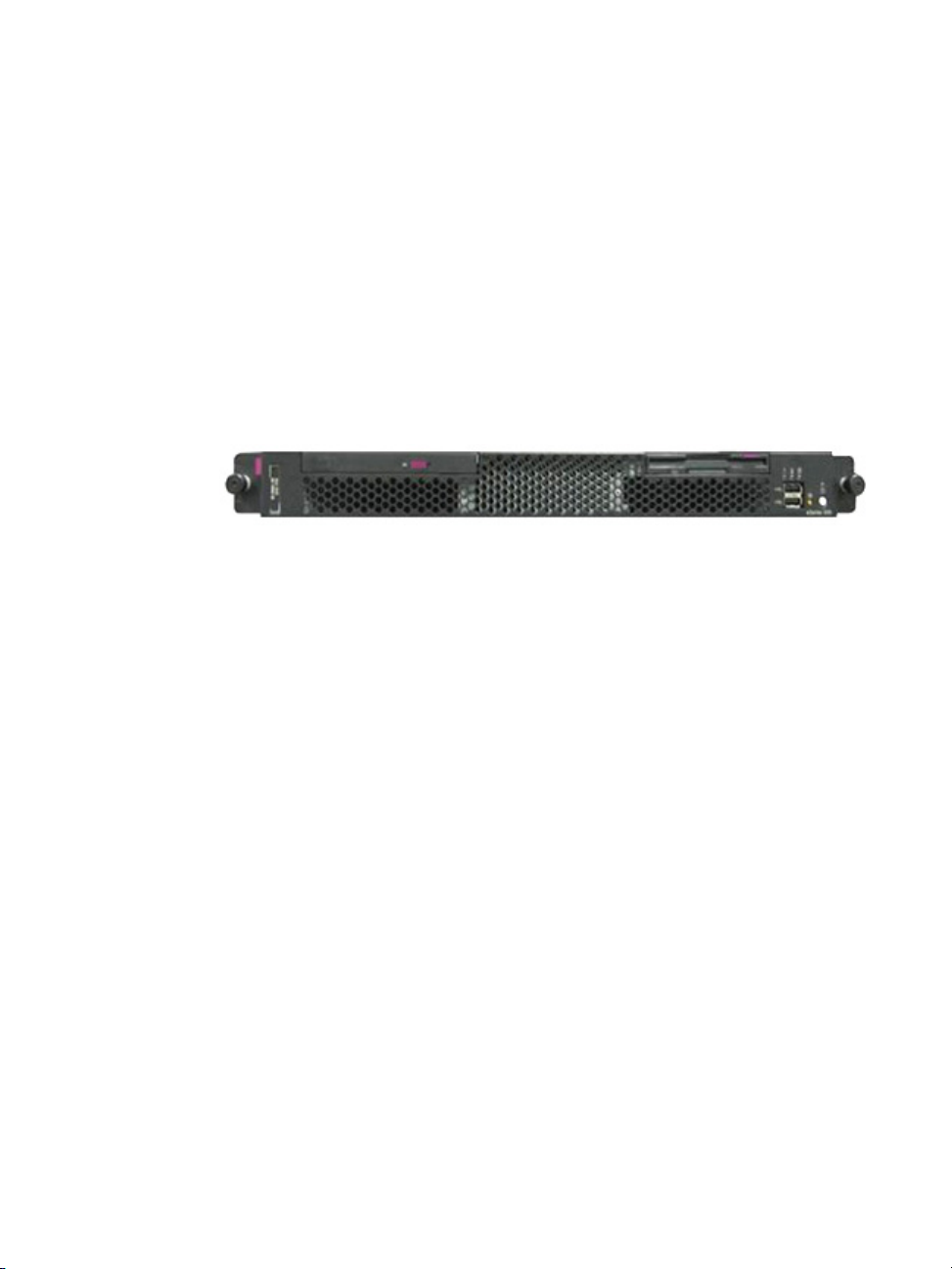
Connectivity and Capacity
The BladeManager hardware platform is based on the IBM eServer xSeries
306. It comes with a Blade Wizard which enables the admin user to create up
to 14 blades and 4 switches for each chassis. The BladeManager supports up
to 6 chassis; altogether, the module support a maximum of 84 blades and 24
switches.
All blades have Serial over LAN (SOL), KVM/IP, virtual media, and power
options created. For security, blade users are controlled by the Control Access
List (ACL) which is configured through the Security Profile settings.
The switches connect as secondary or cascaded devices to the chassis.
Front view of the BladeManager:
See Chapter 2: BladeManager Installation to view the port connections
available from the BladeManager.
Key Features
The key features of AlterPath BladeManager are:
• Single point security gateway
• Centralized authentication
• Consolidated views
• One-click access to consoles and devices
• Centralized data logging system
• Access log audit trail
• Log file compression and rotation capabilities
• Prioritized triggers and alarms
•Blade wizard
• Device, Console, and User Group Management
• Backup, restore, and replicate user data
• Exhaustive reporting
• Convenient web user interface
• Easy command line interface
• Product maintenance
1-2 AlterPath BladeManager Manual
Page 19

Key Features
Single Point Security Gateway
Centralized Authentication
Consolidated Views and Blade Access
The BladeManager has been designed such that communication between
users and the management network must pass through a single point of access
(the BladeManager) to optimize security and enforce adherence to your
corporate security policy.
A single, secure access point reduces management overhead for managing
blade servers. Moreover, the multiple authentication options available ensures
compatibility with existing infrastructure.
Centralized authentication saves the user or administrator from using a
password for each blade server, and thereby maintain a secure password. You
need only use your password once upon logging onto the BladeManager. To
access the blade servers and switch modules, the BladeManager provides the
following authentication methods: local database, RADIUS, LDAP,
Kerberos, Tacacs+, NIS and active_directory.
The BladeManager provides secure OS, POST and BIOS access to individual
blades and switch modules.
From the BladeManager web interface, you can view a list of all blades to
which you have authorized access. Information about each blade includes
blade name, port, location, description, and status. For added security, users
cannot view blades which they are not authorized to use.
Simple and Easy Web User Interface
The BladeManager provides a convenient and user-friendly web user
interface for the regular user and the administrator. Hyperlinks enable you to
access consoles, view data logs, and other information even faster. From one
single interface, you can achieve just about everything you need to manage
your network’s consoles.
Users can only view and access those blades and switches to which they are
assigned. This customization adds security to the system since users cannot
view or access any blade or switch that does not concern them.
AlterPath BladeManager Manual 1-3
Page 20

1: Introduction
One-Click Access to Blades and Switches
Centralized Data Logging System
Placing the mouse cursor over a chassis name from the Chassis List form
allows the system administrator to access the BladeManager through the web
or CLI. The default session type is configurable.
To access a blade, the regular user can choose and click on any blade or
switch listed on the Blades List form. This opens a console session (through
Secure Shell) for that particular blade, allowing the user to remotely fix
problems related to the target blade.
By placing the mouse cursor over a blade or switch console name from the
Blades List form, the user can select KVM, serial over LAN (SOL), or to
power ON/OFF the selected blade or switch.
The BladeManager provides continuous online and offline data logging of all
system messages. It captures all console log messages and writes them to its
internal hard disk drive. With a console log capacity of 20GB, the secure
online/offline storage ensures availability of all important console messages.
Each line of the logfile contains a timestamp (a feature which prevents
tampering) and provides a tool for analyses and audit trailing. Each time a
user connects to a blade or switch, BladeManager adds a timestamp to the log
file. The user identification timestamp is recorded in the data buffer and
logged separately on the BladeManager access log database.
Log File Compression and Rotation
When a log file reaches a certain size (which is specified by the
administrator), the system automatically compresses the file and then creates
a new file to collect a new set of console data. The file rotation should be
seamless with no data loss as the system copies from one file to another.
The administrator has the option to move the compressed log file to another
server for archiving.
Prioritized Triggers & Alarms
BladeManager’s event handling feature enables the system to identify
possible issues and alert the user. As the BladeManager sends a message to
the hard disk for storing and consolidation, it also scans the message for
1-4 AlterPath BladeManager Manual
Page 21

Key Features
Blade Wizard
triggers. A trigger is a text string pre-defined by the administrator which the
system uses to detect a trigger text from messages. When the BladeManager
detects a trigger text, based on how the trigger was configured by the
administrator, it does the following:
• Send an email to a user list
• Create a prioritized alarm entry in the Alarm database
• Write a log message to the BladeManager logging system to acknowledge
the trigger.
Other Alarm Features
• Notes - You can add notes to an alarm to indicate what action you have
taken. These notes can be useful for future reference to similar issues.
• Reports - You can generate a report to show what actions were taken by
whom, and how long it took to fix the issue.
The blade wizard allows the system administrator to define the blades
automatically using default and customized values. The wizard automatically
configures the selected blade(s) and switch(es) and applies them. The wizard
saves the time-consuming task of configuring each blade and switch
manually.
Chassis, Blades, and User Group Management
Chassis, blades, and users can be grouped to further simplify the organization
and management of these system components. The administrator may create,
update and delete any of the groups at anytime through the web management
interface. Users can view only those groups to which they belong or have
access.
Backup, Restore, and Replicate User Data
This feature allows users to create a backup of the BladeManager
configuration and data files. The backup includes data from the compact
flash, configuration data from the database, and log data from the console
buffer files. This feature also enables users to copy console log files to a
server for further analysis and archiving.
AlterPath BladeManager Manual 1-5
Page 22

1: Introduction
Exhaustive Reporting
Multiport Ethernet Cards
Command Line Interface (CLI)
Because the BladeManager consolidates all its logs and maintains its own
databases, it provides in-depth reporting capabilities to suit the reporting
needs of users and managers.
The BladeManager supports up to two multiport PCI ethernet cards for secure
networks that use multiple network segments. This enables the BladeManager
to physically separate devices and connect to multiple network segments.
The Ethernet cards are detected by the configuration wizard during boot time.
For emergency access situations, the BladeManager can provide you with a
command line interface by making a regular Secure Shell connection to the
BladeManager.
CLI is one of two user interfaces (the other is the web interface) available to
BladeManager users. The CLI is also used for First Time Configuration and
system recovery procedures.
1-6 AlterPath BladeManager Manual
Page 23
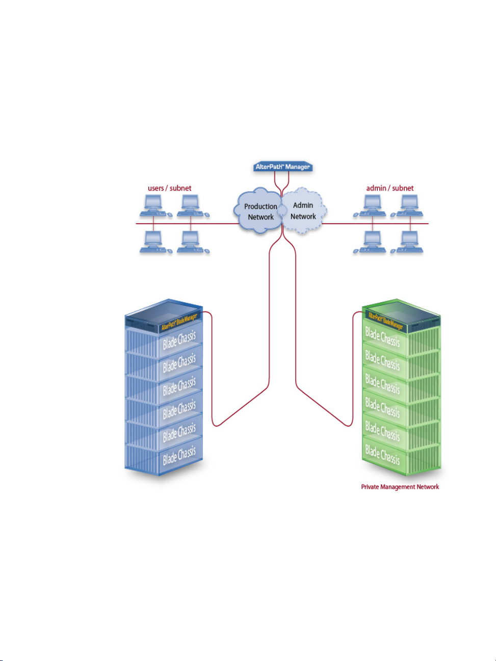
Deploying the BladeManager
Deploying the BladeManager
The diagram below shows how the BladeManager may be set up to connect to
a management network and a public network. Equipped with its own Ethernet
switches, the two networks are physically separated. Any BladeManager user
who needs to access a blade server or switch must authenticate and pass
through the BladeManager.
AlterPath BladeManager Manual 1-7
Page 24

1: Introduction
1-8 AlterPath BladeManager Manual
Page 25

Chapter 2
BladeManager Installation
This section discusses the procedures and requirements for installing the
AlterPath BladeManager, and is organized as follows:
• Product Installation Checklist
• Rack Mounting Guidelines
• Major Components of the BladeManager
• Installing a DIMM
• Installing a Hard Disk Drive
• Installing a Simple-Swap Serial ATA Hard Disk Drive
• Installing a SCSI Hard Disk Drive
• Installing an Adapter
• Completing an Installation
• Connecting the Cables
• Updating the Server Configuration
• Preparing Console for Initial Configuration
Product Installation Checklist
Your AlterPath BladeManager is shipped with the following hardware
components:
• BladeManager
• Console cable (null modem)
• Power cable
• 2 Ethernet cables
• Mounting kit
Page 26

2: BladeManager Installation
Rack Mounting Guidelines
When rack-mounting the BladeManager, consider the following:
• Ensure the room temperature is below 35
• If you install the BladeManager in a closed or multi-rack assembly, the
operating ambient temperature of the rack environment may be greater
than the room ambient temperature. Ensure that you install the equipment
in an environment compatible with the manufacturer’s maximum rated
ambient temperature.
• Do not block any air vents. Usually, 15 cm (6 in.) of air space provides
proper airflow.
• Plan the device installation starting from the bottom of the rack cabinet.
• Install the heaviest device in the bottom of the rack cabinet.
• Do not extend more than one device out of the rack cabinet at the same
time.
• Connect all power cords to properly wired and grounded electrical
outlets.
• Maintain reliable earthing of rack mounted equipment by inspecting
supply connections other than direct connections to the branch circuit
such as power strips or extension cords.
• Do not overload the power outlet when installing multiple devices in the
rack.
• Remove the rack doors and side panels to provide easier access during
installation.
• The slide rails in the kit come preset to the correct length for installing in
an IBM rack cabinet and they are adjustable for other rack cabinets.
• The slide rails are marked RIGHT/FRONT and LEFT/FRONT for proper
placement on the rack-cabinet flanges.
• Ensure that the equipment is mounted or loaded evenly to prevent a
potentially hazardous condition.
• Do not place any object weighing more than 50 kg (110 lb) on top of rackmounting devices.
o
C (95o F).
2-2 AlterPath BladeManager Manual
Page 27
Rack Mounting Guidelines
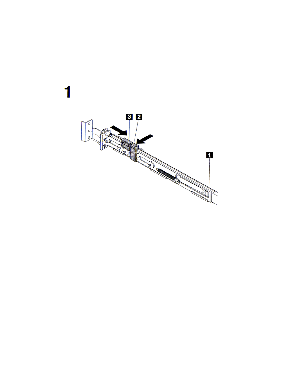
To install the BladeManager in a rack cabinet, you need the following items:
• 2 slide rails
• 6 cable straps
• 6 M6 screws (for shipping and for securing vibration-prone areas)
a. Press on the rail-adjustment bracket (1) on the rear of the slide rail to
prevent the bracket from moving.
b. Press on tab (2) and tab (3) and slide the rail-locking carrier toward
the front of the slide rail until it snaps into place.
c. Press on tab (2) and tab (3) on the front rail-locking carrier and slide
the rail-locking carrier toward the rear of the slide until it snaps into
place.
AlterPath BladeManager Manual 2-3
Page 28
2: BladeManager Installation
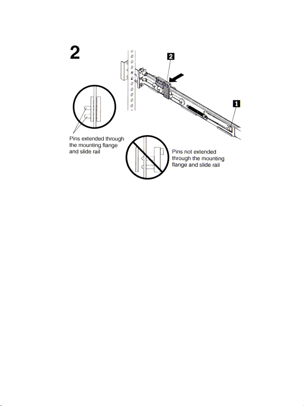
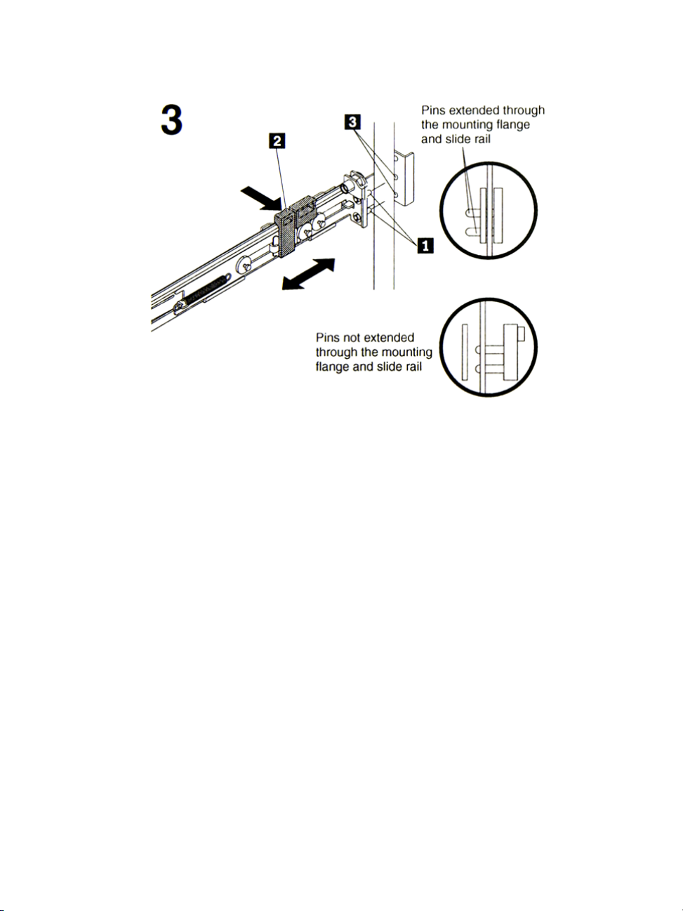
a. Lift the release tab (1) and fully extend the rail-adjustment bracket
from the rear of the slide rail until it snaps into place, if you need to
adjust the slide rail length.
b. Align the pins on the rear rail-locking carrier with the holes on the
rear mounting flange.
c. Press the tab (2) to secure the rear of the slide rail to the rear
mounting flange.
Important: Ensure that the pins are fully extended through the mounting
flange and slide rail.
2-4 AlterPath BladeManager Manual
Page 29
Rack Mounting Guidelines
a. Align the pins (1) on the front rail-locking carrier to the front
mounting flange.
b. If you adjusted the rail length, push the rail-locking carrier back
toward the rear of the slide rail to align the slide rail with the
mounting flange.
c. Press the tab (2) to secure the front of the slide rail to the front
mounting flange.
d. Repeat steps 1 and 2 for the other slide rail.
AlterPath BladeManager Manual 2-5
Page 30
2: BladeManager Installation
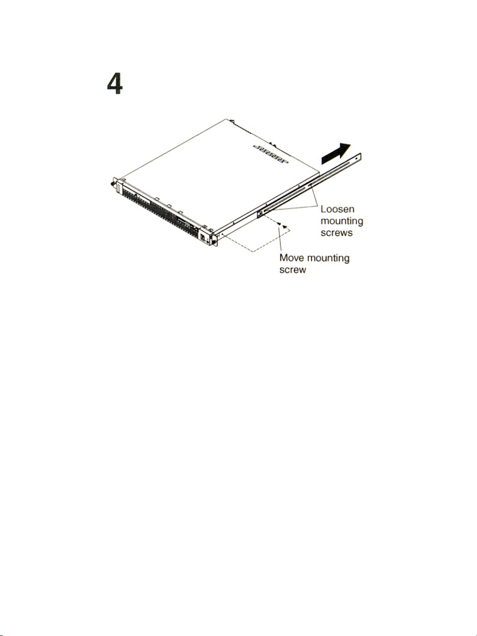
a. If you plan to transport the rack cabinet to another location with the
server installed, remove one screw and loosen the other screws as
indicated.
b. Fully extend the rail and re-insert the screw and tighten all screws to
secure the rail.
c. If you do not plan to transport the rack cabinet with to another
location with the server installed, continue with step 5.
2-6 AlterPath BladeManager Manual
Page 31

Rack Mounting Guidelines
a. Align the server on the slide rails and push the server fully into the
rack cabinet. Secure the server to the front mounting flanges with the
captive thumbscrews (1).
Note: You must leave the shipping brackets (2) attached to the slide rails
unless the shipping brackets impede the server from sliding fully in the
rack cabinet. If you need to remove the shipping brackets, continue
with the next step.
AlterPath BladeManager Manual 2-7
Page 32

2: BladeManager Installation
a. Press on the release tab (1) as indicated on the shipping bracket, and
remove the shipping from the slide rail.
b. Repeat previous step for the other shipping bracket.
c. Store the shipping bracket for future use.
Note: You just re-install the shipping brackets on the slide rails before you
transport the rack cabinet with the server installed. To re-install the
shipping brackets, reverse this step.
2-8 AlterPath BladeManager Manual
Page 33

Rack Mounting Guidelines
a. Attach cables to the rear of the BladeManager (such as keyboard,
mouse, monitor cables, as needed).
b. Route the cables to the left corner of the BladeManager (as viewed
from the rear) and use the cable straps to secure the cables to the slide
rails.
AlterPath BladeManager Manual 2-9
Page 34

2: BladeManager Installation
a. Before you transport the rack cabinet to another location with the
BladeManager installed, you must secure the server to the rack. If
necessary, disconnect the cables from the rear of the server; then,
slide the server out of the rack 150 mm (6 in.) and insert the M6
screws in each slide rail.
b. Secure the server or the rack cabinet with the M6 screws.
c. Ensure the rails are fully extended to the rear of the rack cabinet and
that the shipping brackets are installed.
d. Go to steps 4, 5, and 6 for instructions.
2-10 AlterPath BladeManager Manual
Page 35

Major Components of the BladeManager
Major Components of the BladeManager
The BladeManager hardware platform is based on the IBM eServer 306. It’s
basic components are as follows:
• Blue on a component indicates touch points where you can hold the
component such as when you remove it from or install it in the server.
• Orange on or near a component indicates that you can hot-swap the
component (that is, you can remove or install the component while the
BladeManager is running).
• Orange can also indicate touch points on hot-swappable components.
AlterPath BladeManager Manual 2-11
Page 36

2: BladeManager Installation
Installation Safety Guidelines
System Reliability Guidelines
To help ensure proper cooling and system reliability, make sure that:
• Each of the drive bays has a drive tray installed in it.
• If the server has redundant power, each of the power-supply bays has a
power supply installed in it.
• Allow the server cooling system to work properly by leaving
approximately 50mm (2.0 in.) of open space around the front and rear of
the server.
• There are no objects in front of the fans.
• You follow cabling instructions that come with optional adapters.
• You replace a failed fan within 48 hours.
• You do not remove the air baffle while the server is running since
operating the server without the air baffle might overheat the
microprocessor.
Static-Sensitive Devices
• Static electricity can damage electronic devices, including your server. To
avoid damage, keep static-sensitive devices in their packages until you
are ready to install them.
• Limit your movements as they build up static electricity around you.
• Handle the device carefully, holding it by its edges or frame.
• Do not touch solder joints, pins, or exposed circuitry.
• Do not leave the device where others can handle and damage it.
• While the device is still in its static-protective package, touch it to an
unpainted metal part of the server for at least two seconds to drain static
electricity from the package and from your body.
• Remove the device from its package and install it directly into the server
without setting down the device. If you need to set down the device, place
2-12 AlterPath BladeManager Manual
Page 37

Installation Procedures
it back into its package; do not place the device on your server or on a
metal surface.
• Take extra care when handling devices during cold weather as heating
reduces indoor humidity and increases static electricity.
Installation Procedures
This section provides the following procedures:
• Installing DIMMs
• Installing a Simple-Swap Serial ATA Hard Disk Drive
• Installing a SCSI Hard Drive
• Installing an Adapter
• Completing the Installation
Installing DIMMs
When installing dual inline memory modules (DIMMs), consider the
following information and guidelines:
• Your server supports 256 MB, 512 MB, and 1 GB DIMMs, for a
maximum of 4 GB of system memory.
• Depending on the server configuration, the installation will reduce the
amount of usable memory. A certain amount of memory must be reserved
for system resources. The BIOS displays the total amount of installed
memory and the amount of configured memory.
• Your server comes with one 512 MB DIMM installed in DIMM
connector 1. If your system has one DIMM installed, when you install an
additional DIMM, you must install it in DIMM connector 3, and it must
be the same size, speed, type, and technology as the DIMM installed in
DIMM connector 1. You can mix compatible DIMMs from various
manufacturers.
• If you install a second pair of DIMMs in DIMM connectors 2 and 4, they
do not have to be the same size, speed, type and technology as the
DIMMs installed in DIMM connectors 1 and 3. However, the size, speed,
type and technology of the DIMMs you install in connectors 2 and 4 must
match each other.
• Install only 2.5 V, 184-pin, double-data-rate (DDR), PC2700 or PC3200,
unbuffered synchronous dynamic random-access memory (SDRAM)
AlterPath BladeManager Manual 2-13
Page 38

2: BladeManager Installation
with error correcting code (ECC) DIMMs. These DIMMs must be
compatible with the latest PC2700 and PC3200 SDRAM unbuffered
DIMM specification.
• When you restart your server, the system displays a message indicating
that the memory configuration has changed.
To install a DIMM, complete the following procedure:
1. Review the preceding installation guidelines.
2. Switch off the server and peripheral devices, and disconnect the power
cord and all external cables.
3. Remove the Cover.
Caution: To avoid breaking the retaining clips or damaging the DIMM
connectors, open and lose the clips gently.
4. Open the retaining clip on each side of the DIMM connector.
5. Touch the static-protective package containing the DIMM to any
unpainted metal surface on the server. Then, remove the DIMM from the
package.
2-14 AlterPath BladeManager Manual
Page 39

Installation Procedures
6. Turn the DIMM so that the keys align with the slot.
7. Insert the DIMM into the connector by aligning the DIMM edges with the
slots at each end of the DIMM connector. Firmly press the DIMM straight
down into the connector by applying pressure on both ends of the DIMM
simultaneously. The retaining clips snap into the locked position when the
DIMM is firmly seated in the connector. If there is a gap between the
DIMM and the retaining clips, the DIMM has not been inserted correctly;
open the retaining clips, remove and reinsert the DIMM.
8. If you have other options to install, do so now.
9. Replace the cover.
10. Go to Completing the Installation, this chapter.
Installing a Hard Disk Drive
Follow the documentation that comes with the hard disk drive in addition to
the instructions in this chapter.
Installing a Simple-Swap Serial ATA Hard Disk
Drive
To install a simple-swap Serial ATA hard disk drive, complete the following
procedure:
Note: If you have only one hard disk drive, install it in the left drive bay.
1. Review the installation safety guidelines ar the beginning of this chapter.
2. Switch off the server and peripheral devices, and disconnect the power
cord and all external cables.
3. Press the release tabs on the bezel and pull the bezel away from the
server.
4. Slide the drive into the server until it connects to the backplane.
5. If you have other options to install, do so now.
6. Reinstall the bezel.
7. Go to Completing the Installation, this chapter.
AlterPath BladeManager Manual 2-15
Page 40

2: BladeManager Installation
Installing a SCSI Hard Drive
To install a SCSI hard drive, complete the following procedure:
NOTE: If you have only one hard disk drive, install it in the left drive bay.
1. Review the safety installation guidelines at the beginning of this chapter.
2. Switch off the server and peripheral devices; disconnect the power cord
and all external cables.
3. Remove the cover.
4. Press the release tabs on the bezel and pull the bezel away from the server.
5. Slide the drive tray out of the server, and then position the drive on the
drive tray.
6. Secure the drive using the screws that come with the option.
7. Slide the drive tray back into the server.
8. Connect the signal and power cables to the drive
2-16 AlterPath BladeManager Manual
Page 41

Installation Procedures
9. If you have other options to install, do so now.
10. Re-install the bezel and replace the cover. Go to Completing the
Installation, this chapter.
Installing an Adapter
This section describes the types of adapters that your server supports and
other information to consider when installing as adapter.
• In addition to the instructions in this section, follow the instructions that
come with the adapter.
• Your server comes with two peripheral component interconnect-extended
(PCI-X) adapter slots located on the riser card assembly. You must first
remove the riser card assembly to access the PCI-X connectors.
• There are two 64-bit 66 MHz PCI-X slots.
• You can install one low profile half-length adapter in expansion slot 1 and
one full-height, three-quarter length adapter in expansion slot 2.
• The BladeManager supports 3.3 V or universal adapters.
AlterPath BladeManager Manual 2-17
Page 42

2: BladeManager Installation
• The BladeManager uses a rotational interrupt technique to configure PCIX adapters so that you can install PCI-X adapters that do not support
sharing of PCI-X interrupts.
• The BladeManager scans PCI-X slots to assign system resources. If you
have not changed the default startup sequence, the BladeManager starts
devices in the following order:
a. CR-ROM and diskette drives
b. PCI-X slot 2
c. PCI-X clot 1
d. Integrated Ethernet controllers
• The optional Remote Supervisor Adapter II can be installed only in PCIX slot 2.
• You can install an optional RAID controller in your server to control the
internal hard disk drives (for example, to allow you to configure the
internal hard disk drives into disk arrays.
• The optional ServeRAID-7t S-ATA controller can be installed only in
PCI-X slot 1. The low-profile bracket that comes with the controller is
required to install the controller.
• The optional ServeRAID-6i+ controller can be installed only in PCI-X
slot 1. The low-profile bracket that comes with the controller is required
to install the controller.
• No re-routing of the internal SCSI cable (SCSI models only) is required if
you are installing the ServeRAID-6i+ controller. The ServeRAID-6+
controller uses the SCSI connector (SCSI models only) for output.
2-18 AlterPath BladeManager Manual
Page 43

Installation Procedures
To install an adapter, complete the following procedure:
1. Review the safety installation guidelines at the beginning of this chapter.
2. Switch off the server and peripheral devices; disconnect the power cord
and all external cables.
3. Remove the cover.
4. Follow the cabling instructions that come with the adapter. Route the
adapter cables before you install the adapter.
5. Follow the instructions that come with the adapter to set jumpers or
switches, if any.
6. Loosen the captive screw on the rear of the server and remove the risercard assembly. Place the riser-card assembly on a flat, static-protective
surfaced.
AlterPath BladeManager Manual 2-19
Page 44

2: BladeManager Installation
7. Remove the expansion-slot cover.
Important: PCI expansion-slot covers must be installed on all vacant slots.
This maintains the electronic emissions characteristics of the
server and ensures proper cooling of server components.
8. Touch the static-protective package containing the adapter to any
unpainted metal surface on the BladeManager. Then, remove the adapter
from the static-protective package. Avoid touching the components and
gold-edge connectors on the adapter.
9. Place the adapter, component side up, on a flat, static-protective surface
and set any jumpers or switches as described by the adapter manufacturer,
if necessary.
Important: When you install an adapter in the riser-card assembly, carefully
grasp the adapter by its top edge or upper corners, and align it
with the PCI-X expansion slot; then, press the adapter firmly
into the expansion slot.
10. Re-install the riser-card assembly. Ensure that the riser-card assembly is
fully seated in the riser-card connector.
2-20 AlterPath BladeManager Manual
Page 45

Installation Procedures
11. Tighten the captive screw on the rear of the server.
12. If you have other options to install, do so now.
13. Replace the cover. Go to Completing the Installation, this chapter.
Completing the Installation
To complete the installation, follow the steps below:
1. Re-install the cover.
2. Install the server in the rack cabinet.
Attention:
Install your server only in a rack cabinet with perforated doors.
Do not leave open space above or below an installed server in your rack
cabinet. To help prevent damage to server components, always install a
filler panel to cover the open space and to help ensure proper air
circulation. See the documentation that comes with your rack cabinet for
more information.
3. Connect the cables and power cords. See Connecting the Cables, this
section.
4. Update the server configuration. See Updating the Server Configuration,
this section.
AlterPath BladeManager Manual 2-21
Page 46

2: BladeManager Installation
Connecting the Cables
The diagrams below show the locations of the input and output connectors on
the front and rear of the BladeManager.
1. Switch off the server before connecting (or disconnecting) cables from
your server.
2. See the documentation that comes with your external devices for
additional cabling instructions. It might be easier for you to route cables
before you connect devices to the BladeManager.
3. Cable identifiers are printed on the cables that come with the
BladeManager. Use these identifiers to connect the cables to the correct
connectors.
4. There is one keyboard connector on the back of the server. Use this
connector to connect the server to a keyboard or optional console switch.
You can also connect a USB keyboard to the server using one of the USB
ports. After installing a USB keyboard, you might need to use the
Configuration/Setup Utility program to enable keyboardless operation
and prevent the POST error message 301 from displaying during startup.
For more information about this option and how to connect it to the
BladeManager, see the documentation that comes with the option.
2-22 AlterPath BladeManager Manual
Page 47

Updating the Server Configuration
Updating the Server Configuration
When you start the BladeManager for the first time after you add or remove
an internal option or external SCSI device, you might receive a message that
the configuration has changed. The Configuration/Setup Utility program
starts automatically so that you can save the new configuration settings.
Some options have device drivers that you need to install. See the
documentation that comes with the device information about installing any
required device drivers.
If the server has a RAID configuration using the SCSI controller with
integrated RAID (SCSI models only) or the integrated Serial ATA controller
with RAID and you have installed or removed a hard drive, you might have to
reconfigure your disk arrays. See the RAID documentation on the IBM
ServeRAID-7e (Adaptec HostRAID) Support CD for more information about
reconfiguring the disk arrays.
If the server has an optional RAID adapter and you have installed or removed
a hard disk drive, see the documentation that comes with the RAID adapter
for information about reconfiguring the disk arrays.
BladeManager Controls, LEDs, and Power
This section describes the controls and light-emitting diodes (LEDs) and how
to switch the BladeManager on and off.
Front View
The diagram below shows the controls and LEDs on the front of the
BladeManager.
AlterPath BladeManager Manual 2-23
Page 48

2: BladeManager Installation
Front LEDs/Buttons Function
CD-eject button Press this button to release a CD from the
CD-ROM.
CD-ROM drive activity
LED
When lit, it indicates that the CD-ROM
drive is in use.
Diskette drive activity LED When lit, it indicates that the diskette
drive is in use.
Diskette-eject button Press this button to release a diskette from
the diskette drive.
System-error LED When lit, it indicates that a system error
has occurred.
System-locator LED Use this blue LED to visually locate the
BladeManager if it is in a location with
numerous other servers. If your server
supports IBM director, you can use IBM
Director to light this LED remotely.
Hard disk drive activity
LED
When flashing, it indicates that a hard
disk drive is in use.
Power-on LED When lit and not flashing, it indicates that
the server is switched ON. When flashing,
it indicates that the server is switched OFF
and still connected to an AC power
source. When off, it indicates that AC
power is not present, or the power supply
or the LED itself has failed.
If this LED is off, it does not mean that
there is no electrical power in the
BladeManager. The LED might be burned
out. To remove all electrical power from
the server, you must disconnect the power
cord from the electrical unit.
2-24 AlterPath BladeManager Manual
Page 49

BladeManager Controls, LEDs, and Power
Front LEDs/Buttons Function
Power-control button Press this button to switch the server ON
Reset button Press this button to reset the server and
Rear View
The diagram below shows the LEDs on the rear of the BladeManager.
and OFF manually.
run the power on self-test (POST). You
might have to use a pen or the end of a
straightened paper clip to press the button.
Rear LEDs Function
Ethernet 1 transmit/receive
activity LED
This LED is on the Ethernet connector.
When lit, it indicates that there is activity
between the BladeManager and the
network.
Ethernet 1 speed 1 Gbps LED This LED is on the Ethernet connector.
When lit, it indicates that the Ethernet
network speed is 1 Gbps. When off, it
indicates that the Ethernet network speed
is 10 Mbps or 1000 Mbps.
AlterPath BladeManager Manual 2-25
Page 50

2: BladeManager Installation
Rear LEDs Function
Ethernet 2 speed 1 Gbps LED This LED is on the Ethernet connector.
When lit, it indicates that the Ethernet
network speed is 1 Gbps. When off, it
indicates that the Ethernet network speed
is 10 Mbps or 100 Mbps.
Ethernet 2 transmit/receive
activity LED
This LED is on the Ethernet connector.
When lit, it indicates that there is activity
between the BladeManager and the
network.
BladeManager Power Features
When the BladeManager is connected to an AC power source but is not
switched on, the operating system does not run, and all core login except for
the service processor is shut down. However, the server can respond to
requests from the service processor, such as a remote request to turn on the
server. The power-on LED flashes to indicate that the server is connected to
AC power but not switched on.
Switching On the Server
Approximately 20 seconds after the BladeManager is connected to AC power,
the power-control button becomes active, and you can switch on the
BladeManager and start the operating system by pressing the power-control
button.
You can also switch on the BladeManager in any of the following ways:
• If a power failure occurs while the BladeManager is switched on, the
BladeManager will start automatically when power is restored.
• If the BladeManager is connected to an Advanced System Management
interconnect network that contains at least one server with an optional
Remote Supervisor Adapter II installed, the BladeManager can be
switched on form the Remote Supervisor Adapter II user interface.
• If your operating system supports the system-management software for an
optional Remote Supervisor Adapter II, the system-management software
can switch on the BladeManager.
2-26 AlterPath BladeManager Manual
Page 51

BladeManager Power Features
• If your operating system supports the Wake on LAN feature, the Wake on
LAN feature can switch on the BladeManager.
Note: When 4 GB or more memory (physical or logical) is installed, some
memory is reserved for various system resources and is unavailable to
the operating system. The amount of memory that is reserved for
system resources depends on the operating system, the BladeManager
configuration, and the configured PCI options.
Switching Off the BladeManager
When you switch off the BladeManager and leave it connected to AC power,
the BladeManager can respond to requests from the Service processor, such
as a remote request to turn on the server. To remove all power from the server,
you must disconnect it form the power source.
Caution: The power control button on the device and the power switch on
the power supply do not turn off the electrical current supplied to
the device. The device also might have more than one power cord.
To remove all electrical current from the device, ensure that all
power cords are disconnected from the power source.
You can switch off the BladeManager in any of the following ways:
• You can switch off the BladeManager from the operating system if your
operating system supports this feature. After an orderly shutdown of the
operating system, BladeManager will switch off automatically.
• You can press the power-control button to start an orderly shutdown of
the operating system and switch off the BladeManager if your operating
system supports this feature.
• If the operating system stops functioning, you can press and hold the
power-control button for more than 4 seconds to switch off the
BladeManager.
• If the BladeManager is connected to an Advanced System Management
interconnect network that contains at least one server with an optional
Remote Supervisor Adapter II installed, the BladeManager can be
switched off from the Remote Supervisor Adapter II user interface.
• If an optional Remote Supervisor Adapter II is installed in the server, the
server can be switched off from the Remote Supervisor Adapter II user
interface.
AlterPath BladeManager Manual 2-27
Page 52

2: BladeManager Installation
• If the Wake on LAN feature switched on the BladeManager, the Wake on
LAN can switch off the BladeManager.
• You can switch off the BladeManager through a request from the service
processor.
Pre-Configuration Requirements
Before configuring BladeManager, ensure that you have the following system
set up and information ready:
Requirement Description
HyperTerminal, Kermit,
or Minicom
IP Addresses Have the IP/Mask addresses of the following
NIC Card Ensure that you have a NIC card installed in
Note: To complete the configuration process, SKIP to Chapter 4: Web
Administration and refer to the “First Time Configuration Wizard” on
page 4-4.
If you are using a PC, ensure that
HyperTerminal is installed on your Windows
operating system. If you are using the UNIX
operating system, use Kermit or Minicom.
NOTE: You will need Root Access on your
local UNIX machine in order to use the serial
port.
ready:
- All Console Servers
- Gateway
- DNS
Optional addresses:
- NTP
- SMTP (only when using the alarms feature).
your PC to provide an Ethernet port, and
allow network access.
Note: Chapter 3: BladeManager Web Access is designed for regular users
who will use or operate the application after the BladeManager
administrator has completed the configuration procedures discussed in
chapter 4.
2-28 AlterPath BladeManager Manual
Page 53

Configuring the COM Port Connection and Logging In
Note: For a list of internet browsers and Cyclades device firmware versions
supported by the BladeManager, refer to Appendix A: Hardware
Specifications.
Configuring the COM Port Connection and
Logging In
The console port is used for the initial configuration (also known as First
Time Configuration in this document) which is performed using the
Command Line Interface (CLI) via serial console connection.
First Time Configuration is responsible for establishing the superusers for the
CLI (hardware configuration) and the BladeManager web interface and
configuring the BladeManager connectivity and system settings. The process
is discussed in more detail in Chapter 4: Configuring the BladeManager.
Before using the terminal, make sure it is configured as follows:
1. Select available COM port.
In Hyper Terminal (Start > Program > Accessories), select File >
Properties, and click the Connect To tab. Select the available COM port
number from the Connection dropdown.
2. Configure COM port.
Click the Configure button.
Your PC, considered here to be a “dumb terminal,” should be configured
as follows:
• Serial Speed: 9600 bps
• Data Length: 8 bits
• Parity: None
• Stop Bits: 1 stop bit
• Flow Control: none
• ANSI emulation
3. Power on the BladeManager
4. Click OK on the Properties window.
You will see the BladeManager booting on your screen. After it finishes
booting, you should see the configuration screen.
AlterPath BladeManager Manual 2-29
Page 54

2: BladeManager Installation
2-30 AlterPath BladeManager Manual
Page 55

Chapter 3
BladeManager Web Access
The web interface provides two modes for using the BladeManager based on
the type of user: Access (for operation by regular users) and Admin (for
configuration by system administrators). This chapter explains the procedures
for operating the BladeManager web interface in Access Mode.
Addressed specifically to regular users, this chapter is organized as follows:
• User Interface Overview
• Accessing the BladeManager Web Management Interface
• Logging In
• Using the Alarms forms
• Using the Blades forms
• Using the Logs forms
• Using the User Profile forms
If you are a BladeManager administrator, refer to Chapter 4: BladeManager
Web Administration.
User Interface Overview
The BladeManager user interface (in Access Mode) has four main menu
options:
Menu Option Function
Alarms The Alarms list form is the first form that you
see (or the default form) when you log in. Use
this form to view alarms, update the status of
an alarm or close an alarm after resolving it.
Page 56

3: BladeManager Web Access
Menu Option Function
Blades Use the Blades form to view a list of blades
Logs Use the Logs form to view the Access Logs,
User’s Profile The User’s Profile form displays the profile of
assigned to you. From the list, select the blade
you wish to access, or select the blade from the
drop down menu on the top left, and then click
on Connect.
The blades list form provides access to the
chassis blades and switches.
Events Logs, and Data Buffer for a particular
blade or chassis. You can also access logs from
the Blade List form.
only the user currently logged in. Use the User
Profile to view or modify your own user
information, as well as your own security
profile.
Using the Web Interface as a Regular User
To open the BladeManager web application, perform the following steps:
1. Type in the following URL from your web browser:
https://nnn.nnn.nnn.nnn
Where: nnn.nnn.nnn.nnn is the IP address provided to you by your
BladeManager administrator.
The IP address works for both encrypted (https) and non-encrypted (http)
versions. Cyclades recommends that you use the encrypted version.
Note: To configure the encrypted version, see “Disabling HTTP to Use Only
HTTPS” on page 5-16, Chapter 5: Advanced Configuration.
3-2 AlterPath BladeManager Manual
Page 57

User Interface Overview
2. When the Login screen appears, enter your user name and password as
provided by your system administrator.
3. Select the Login button.
Upon successful login, the Alarms form appears.
Note: The first time BladeManager launches your application screens, the
process will be slow. Once the screens are cached, subsequent retrieval
of screens should be fast.
AlterPath BladeManager Manual 3-3
Page 58

3: BladeManager Web Access
General Screen Features
The diagram below shows the general features of the BladeManager web
interface. The sample form is for illustration only; it is not the first screen that
you see when you log in as a regular user.
Menu panel
showing
Blades as
the selected
menu choice.
Username
and primary
IP address
Online help and
firmware version info.
“Access” tab indicates that
user interface is for regular users.
User view or
data input form
Logout Button
Buttons panel to manage list
The menu panel highlights the currently selected menu option.
Your user name and IP address appears on the lower left hand corner of the
screen.
The Admin tab is visible to regular users with admin rights.
Be sure to select the Logout button on the top right hand corner after you
finish your session.
Sorting a List Form by Column/Field Name
Most, if not all, list forms provide sort, search, and filter functions.
3-4 AlterPath BladeManager Manual
Page 59

Alarms
An underlined column name indicates that the list can be sorted by the
column name. The Blade List form, for example, allows you to sort by Blade,
Type, Device, Location, or Status. To sort by Location, simply click the
column name, Location.
The arrow adjacent to the heading indicates that the list is sorted based on that
heading. The position of the arrowhead indicates the sort order. A downward
arrowhead indicates that the list is alphanumerically arranged in ascending
order; an upward arrowhead, in descending order. You can change the sort
order by clicking on the heading or the arrow.
Search and Filter Functions
When available, you will find the Search and Filter by buttons at the bottom
of the List form.
This allows you to search through a List form by selecting the search category
(i.e., Blade group) from the dropdown field and selecting the Search button.
You can also filter your search by selecting a category from the Filter by
dropdown field and selecting the Filter by button. The system automatically
saves the filtered list.
Alarms
The Alarm List form is the default form of the BladeManager Web Interface
in Access mode. An alarm is a brief message alerting you of a possible
problem that requires an action.
When BladeManager detects an alarm, it sends the alarm along with a ticket
number to the user’s Alarm List form. As a user, you should see only those
alarms assigned to you by your administrator.
If the trigger for the alarm has been configured to send an email, then you
should also receive an email notification regarding the alarm. Each alarm or
ticket in the list includes a timestamp, a priority level, and a status.
AlterPath BladeManager Manual 3-5
Page 60

3: BladeManager Web Access
Alarm Logs
The BladeManager not only stores each alarm in a database, but also
maintains a log for each alarm. There are two ways in which you can view
alarm logs:
• From the Alarms List form
• From the Logs form (Logs > Data Buffer)
Responding to an alarm
Since no two issues are exactly the same, you have several ways to respond to
an alarm depending on its nature and severity. A “typical” procedure for
responding to an alarm is as follows:
• Accept the ticket or assignment.
• Reassign the ticket or assignment to another user, and optionally add
notes about the ticket.
Once assigned, the user working on the ticket can perform any of the
following procedures to resolve the alarm or complete the ticket:
• View Blade Log and other related logs.
• Edit information ticket by changing the status and adding notes.
• Connect to the blade.
• Run a console session.
• If problem is fixed, change the alarm status and close the ticket.
• Re-assign the ticket to another user.
Alarm List Form
When you first log in to the BladeManager as a regular user or select Alarms
from the menu, the Alarm List form is the first form that you will see. Use this
form to view the list of alarms, to connect to a blade, and to view blade logs.
3-6 AlterPath BladeManager Manual
Page 61

Alarms
To re-assign the current ticket, change the ticket status, and add notes or
comments, use the Alarm Detail (or Ticket Info) form.
Table 3-1: Form Fields and Elements
Fieldname Definition
Ticket Ticket number assigned to an alarm. The
symbol above the ticket number indicates the
severity level of the alarm. Select the number
to display the Alarm Detail form.
Blade Blade from which the alarm originated. Click
on the blade name to enable a console session
according to the type of configured device and
console. For example, a serial console will
establish a text-based session; a KVM console
will launch the KVM viewer, and an IPMI
console will launch the SSH applet and
connect to the IPMI SOL console.
AlterPath BladeManager Manual 3-7
Page 62

3: BladeManager Web Access
Table 3-1: Form Fields and Elements
Fieldname Definition
Blade Config Blade configuration. Select this to view the
Alarm Trigger The Alarm Trigger name. Click on the name to
User Assigned User assigned to the alarm.
Status Status of the alarm.
Blade Log Select this to navigate to the Data Buffer log
Viewing the Alarm Detail Form
The Alarm Detail form contains detailed information about the ticket as
generated by an alarm. It allows you to re-assign the ticket, update the status,
and enter notes regarding the alarm or ticket.
Blade Detail form (which includes the
secondary form: Console Notify, Console
Access, and Console Group) for the particular
console record.
view the Alarm Trigger Detail form.
pertaining to the blade.
To view the ticket information for an alarm, follow the steps below:
1. From the Alarm List form, click on the ticket number.
3-8 AlterPath BladeManager Manual
Page 63

Alarms
The form brings up the Alarm Detail form.
Table 3-2: Form Fields and Elements
Fieldname / Button Definition
Assigned Users Dropdown box that lists all the assigned users
for the current alarm. Select a user to assign or
re-assign ticket to another individual user.
Status Dropdown box to select the status of the ticket.
Messages The system-generated message(s) pertaining to
the alarm.
Notes Text entry box for entering notes or comments
about the current ticket or alarm.
Back Button to return to the Alarm List form.
Save Button to save your entries.
Reset Button to reset the form to its original or default
values.
AlterPath BladeManager Manual 3-9
Page 64

3: BladeManager Web Access
>> Viewing Alarm or Console Logs
You can view the console log for a particular alarm or ticket from the Alarm
List form. To view the console log, follow the step below:
1. From the Alarm List form, under the Console Log column heading, select
the corresponding view link for the console log you wish to view.
The system displays the Logs form:
>> Assigning a Ticket to a User
To assign or re-assign a ticket to a user, follow these steps:
1. From the Alarm List form, select an alarm or ticket to open the Alarm
Detail or Ticket Information form.
The system opens the Alarm Detail form.
2. From the Ticket Information form, select user from the Assigned Users
dropdown list box.
3. If applicable, select the status from the Status dropdown list box.
4. If applicable, type in your notes or comments in the Notes text entry box.
5. Select Save to complete your entry.
3-10 AlterPath BladeManager Manual
Page 65

Blades
Blades
>> Viewing the Blade List
Selecting Blades from the menu brings up the Consoles List form which
allows you to:
• View detailed information about the blade consoles and switches assigned
to you.
• Open a command line console session for a selected blade or switch.
• Launch the KVM Viewer and connect you to a KVM port (for KVM/net)
• Power ON or OFF the selected blade or switch.
Access to blades and switches and the types of connection are configured by
the System Administrator from the Security Profile. You can view your
security profile by going to Users > Security.
The Blades List form allows you to view the blades to which you have
authorized access.
To view the Blade List form, follow this step:
1. From the Blades form, under the Config column, select the view link
adjacent to the blade you wish to view.
AlterPath BladeManager Manual 3-11
Page 66

3: BladeManager Web Access
The Blade List form appears.
Table 3-3: Form Fields and Elements
Column or Button
Definition
Name
Blade Blade or switch name. Place your mouse cursor
over the Blade name to select connection type
(CLI, KVM, VM, ON, OFF).
Type The type of blade as defined in the Blade Detail
form.
Config For each line, select view to open the Blade
Detail form of the selected console.
Chassis Chassis used by the blade.
Port Port number used by the blade.
Location Location of the blade.
Status Operating status (Enabled, Disabled,
OnDemand) of the blade.
3-12 AlterPath BladeManager Manual
Page 67

Blades
Table 3-3: Form Fields and Elements
Column or Button
Name
Save View Button to save the desired blade list and sort
Filter By Button to filter your search by Blade Group
Search Button to search by individual console name
Definition
order.
Name which you select from the dropdown box.
which you select from the dropdown box.
>> Connecting to a Blade Console
To connect to a blade console:
1. From the Blade List form, select the blade you wish to connect to by
selecting the blade name.
Note: If a modem is connected to a remote site, you will experience a slight
delay before connecting to a console.
The system connects you to a console through Secure Shell (SSH).
In KVM/net, the listed console names are the KVM/net ports. Clicking on the
console name will launch the ActiveX application and make a connection to
the port.
Regardless of the type of “console,” the BladeManager handles the
authentication.
Multiple Users and Read/Write Access
Because the BladeManager supports multiple connections to the same port,
this makes it possible for multiple users to view the same form. Note,
however, that only the first user to connect to that port can have full Read and
Write (R/W) access to the blade console panel while the rest can have Read
only (R) access.
Viewing a Blade or Switch
Note: This feature is available only to users of the optional Blade Module.
AlterPath BladeManager Manual 3-13
Page 68

3: BladeManager Web Access
The BladeManager allows you to view individual blades and switches from
the Blade List form. To view a blade or switch, place the mouse cursor over
the blade/switch name to display the list of connect options: CLI (command
line interface), KVM, VM, On (i.e., to power on the blade server), and Off
(i.e., to power off the blade server).
Like all other consoles, as a regular user, you can only view those blade
servers to which you have access. You may also view your user profile with
regards to blade access from the User’s Profile option of the menu, Security
form.
Consoles Detail Form
Use the Blade (or Consoles) Detail form to view specific information about a
particular console (that is, the target blade or console). You can invoke this
form from either the Alarm List form or the Blade List form.
If you have admin privileges, you also use this form to select user(s) to notify
of the alarm and select user(s) to have access to the current blade. Below is an
example of the Blade Detail form.
3-14 AlterPath BladeManager Manual
Page 69

Blades
Table 3-4: Form Fields and Elements
Field Name Definition
Details Button to display the Console Detail form.
Access Button to view users who are authorized to
access the current console.
Notify Button to view users who can be notified of an
alarm pertaining to the current console.
Groups Button to view the group(s) to which the
current console belongs.
Console Name Name of the (target) console.
Device Name Name of the device used by the console.
Port Name of port used by the console.
Status Status of the target console (Able, Disable, On
Demand).
Description A brief description of the console.
Location Physical location of the blade console.
Machine Type Type of target system.
Machine Name Other applicable system name.
OS Type Operating system used by the console.
OS Version Version of operating system.
Back Button to return to the previous page or form.
AlterPath BladeManager Manual 3-15
Page 70

3: BladeManager Web Access
Consoles Access Form
The Consoles Access tabbed form shows the users who are authorized to
access the current blade.
To view the Blade Access form:
1. From the Blade Detail form, click on Access.
The system displays the Blade Access form:
Consoles Notify Form
The Console Notify form shows the users who are notified when an alarm
pertaining to the current console is generated.
To view the Console Notify form:
1. From the Console Detail form, click on Notify.
3-16 AlterPath BladeManager Manual
Page 71

Blades
The system displays the Console Notify form:
In the selection box, a plus (+) sign indicates a group, as opposed to a user.
USER is the default list which contains all users.
Consoles Groups Form
The Console Groups form shows the group(s) to which the current blade
belongs.
To view the Blade Group form:
1. From the Blade Detail form, click on Groups.
AlterPath BladeManager Manual 3-17
Page 72

3: BladeManager Web Access
The system displays the Blade Group form:
Logs
The Logs option of the menu allows you to select and view three types of logs
pertaining to the blade(s) assigned to you:
Log Type Definition
Access Log Logs that provide logging information (i.e.,
who accessed the blade, when and for how
long, etc.) about a particular blade.
Events Log Logs that provide information about
notifications and alarms (who handled the
alarm, what action was taken, etc.) triggered
by a particular blade.
Data Buffer This is a log of all transaction data generated
on the blade.
All three logs are available for the specified blade. To access each log, select
the appropriate log type from the title bar. As with blades and alarms, you can
only view the logs of systems to which you have authorized access.
3-18 AlterPath BladeManager Manual
Page 73

Logs
When you select Logs from the menu panel, the primary form, shown below,
will prompt you for a range of dates from which to retrieve your logs.
Table 3-5: Form Fields and Elements
Field Name Definition
Console Drop down list to select a blade server that
will be the basis of the log(s) to be retrieved.
Date From Drop down list to select the starting date of the
log(s) to be viewed.
Date To Drop down list to select the end date of the
log(s) to be viewed.
Retrieve Button to download the requested log(s) and
display the Log forms.
>> Viewing the Logs
To view the logs available for a specified blade (to which you have authorized
access), perform the following steps:
1. Select Logs from the menu.
AlterPath BladeManager Manual 3-19
Page 74

3: BladeManager Web Access
The system brings up the main Blade Logs form.
2. From the Blade drop down list, select the blade from which you want to
view the logs.
Note: You can only view or access the logs of blades to which you have
authorized access.
3. Select a range of dates from which to base your logs by selecting from the
Date From and Date to drop down lists.
The system brings up the Logs Detail form.
Access Logs
Use Access Logs form to view the Access Logs, Event Logs, and Data Buffer
Logs. The Access Logs (default log browser) provide all access information
(e.g., who accessed the blade, access date, action taken, etc.) about your target
blade server.
The name of the blade/port/chassis to which the logs apply to is shown below
the tab titles.
3-20 AlterPath BladeManager Manual
Page 75

Logs
Table 3-6: Access Logs - Field Definition
Field Name Definition
Date Date in which the event occurred.
Time Time of the event.
User User who connected to the blade.
Action What the user did in response to the alarm.
Status Status of the blade (Enable / Disable).
Connection Type of connection (e.g., SSH, Web); IP
address used.
Event Logs
Use the Event Logs browser to view all events that occurred (within a
specified range of time) on your target blade server.
AlterPath BladeManager Manual 3-21
Page 76

3: BladeManager Web Access
Table 3-7: Event Logs - Field Definition
Field Name Definition
Date Date of the event.
Time Time of the event.
Ticket Ticket number associated with the event.
Pattern Trigger Expression
Action Action taken to resolve event.
Data Buffer
Use the Data Buffer browser to view the contents of the data buffer generated
by a target blade server.
Note: You can also access the Data Buffer log from the Alarms form.
3-22 AlterPath BladeManager Manual
Page 77

User’s Profile
User’s Profile
The User’s Profile form allows you to view your profile or contact
information and modify a limited number of fields. The system allows you to
view only your own profile.
The User’s Profile has four tabbed forms. See the Form Fields and Elements
table for the function of each form.
Table 3-8: Users Profile, Details Form - Fields and Elements
Field Name Definition
Details Tab or button to display the User Detail form.
This is also the primary form of User’s
Profile.
Access Tab/button to display the User Access form
which shows all blades assigned to the current
user.
AlterPath BladeManager Manual 3-23
Page 78

3: BladeManager Web Access
Table 3-8: Users Profile, Details Form - Fields and Elements
Field Name Definition
Groups Tab/button to display the User Group form
Security Tab/button to display the Security form which
User Name The user name used to log into the
Admin User Check box to indicate that the user has Admin
Security Profile Check box to indicate that a security profile
which shows all groups to which the current
user belongs.
shows the security profiles assigned to you. A
security profile defines a user’s access control
to a device, and to which user group that
profile is assigned.
BladeManager.
privileges, and also belongs to the Admin user
group.
has been assigned to the user.
Local Password Check box to indicate that local authentication
applies to the user.
Full Name User’s full name.
Email User’s email. This is the same field name used
by the system for event notification.
Department User’s department.
Location Location of department.
Phone User’s phone number.
Mobile User’s mobile phone number.
Pager User’s pager number.
Status Indicates whether the user is enabled or
disabled.
3-24 AlterPath BladeManager Manual
Page 79

User’s Profile
>> Changing Your Password
>> Viewing the User Access Form
To change your password, perform the following steps:
1. From the User’s Profile detail form, click on Set Password.
2. From the password dialog box, enter the new password twice.
3. Click on Submit.
The User Access form shows the blades that the current user can access.
To view the User Access form:
1. From the User Detail form, click on Access.
The system displays the User Access form:
>> Viewing the User Groups Form
The User Groups tabbed form displays the groups to which you belong.
To view the User Group form:
1. From the User Detail form, click on Groups.
AlterPath BladeManager Manual 3-25
Page 80

3: BladeManager Web Access
The system displays the User Group form:
Table 3-9: User’s Profile, Groups Form - Fields and Elements
Field Name Definition
Groups Tab or button to select the current form.
Select groups for the user List box from which to select a possible list of
user groups assignable to the current user.
Add Button to add a selected user group (left list
box) to the Selected groups list box.
Delete Button to delete a selected user group (right
list box) and return it to the Select groups for
the user list box.
Selected Groups The list box that shows the group(s) assigned
to the current user.
3-26 AlterPath BladeManager Manual
Page 81

User’s Profile
>> Viewing the Security Form
The Security form shows the current security profile assigned to you (for
example, the blades you are allowed to access), including any other applicable
profiles.
To view the Security form:
1. From the menu, select User’s Profile; from the Details form, select the
Security tab.
The system displays the Security tabbed form:
Table 3-10: User’s Profile, Security Form - Fields and Elements
Field Name Definition
Security Tab or button to select the current form.
Select security profile List box from which to select a possible list of
security profiles assigned to the current user.
Add Button to add a selected security profile (left
list box) to the Selected security profiles list
box.
AlterPath BladeManager Manual 3-27
Page 82

3: BladeManager Web Access
Table 3-10: User’s Profile, Security Form - Fields and Elements
Field Name Definition
Delete Button to delete a selected security profile
Selected security profiles The list box that shows the Security Profile
(right list box) and return it to the Select
security profile list box.
assigned to the current user.
Security profiles via user
groups
The list box that shows the Security Profile
assigned to a user group (that is, the default
USER group or any other defined user
groups).
3-28 AlterPath BladeManager Manual
Page 83

Chapter 4
BladeManager Web Administration
This chapter presents the procedures for configuring the AlterPath
BladeManager through the web interface. Addressed to the BladeManager
administrator who must use the web interface in the Admin Mode, the chapter
is organized as follows:
• Operational Modes
• Configuration Process Flow
• First Time Configuration Wizard
• BladeManager Web Interface: Admin Mode
• Forms Summary
• Parts of the Web Interface
• Chassis Management
•Proxies
• Two Methods of Blade Configuration
• Configuring Blades Manually through the Menu
• Deleting a Device Group
• Alarm Trigger Management
• Blades / Switches
• Log Rotation
• Users
• User List form
• Setting the Local Password
•Groups
• Security Profiles
• Backing Up User Data
• System Recovery Guidelines
• BladeManager Database Transaction Support
• Info / Reporting
Page 84

4: BladeManager Web Administration
Operational Modes
The BladeManager provides two operating modes for configuration:
• First Time Configuration (CLI or text-based)
• Admin Mode (GUI-based)
Before you can use the BladeManager web interface you must first run the
First Time Configuration wizard.
The admin user, by default, is the system administrator of the BladeManager
web interface and runs the application in Admin mode. This designation
cannot be revoked. Unless a regular user has been configured to be an admin
user as well (through the User Detail form), regular users can use the
application only in Access mode.
Only an administrator or admin user can use the web interface in Admin
Mode which allows them to perform configuration procedures such as
assigning admin roles to new users, adding new blades and alarms.
Note: For information on how to use the system in Access mode, refer to the
previous Chapter 3: BladeManager Web Access .
Note: Certain configurational procedures (e.g., System Recovery, Modem
Card Configuration) require the use of the CLI by advanced users.
These procedures are discussed in Chapter 5: Advanced
Configuration.
4-2 AlterPath BladeManager Manual
Page 85

Configuration Process Flow
Configuration Process Flow
The entire configuration process through the web interface is as follows:
Connect to
serial console
Perform
First Time
Configuration
SEVEN MENU OPTIONS
Chassis
Chassis
Detail
Group
Blades /
Switches
Blade /
Switch
Detail
Notify
Access
Group
successful?
Blade Manager
Users
User
Detail
Password
Access
Group
Reboot
Y
Logon to
as Admin
N
Alarm
Trigger
Alarm
Detail
Reset system
to default
factory settings
Groups
Chassis
Group
Blade
Group
User
Group
Security
Profiles
Info /
Reporting
AlterPath BladeManager Manual 4-3
Page 86

4: BladeManager Web Administration
You must perform the First Time Configuration process (see Configuration
Flow Diagram) using the command line interface. Once completed, you may
perform the rest of the configuration process and all daily administration
procedures through the BladeManager web interface.
First Time Configuration Wizard
The first time configuration process is designed to:
• Establish user as root, the superuser for the CLI.
• Establish user as Admin, the superuser for the BladeManager web
interface.
• Initialize your system and user settings to ensure full connectivity and
functionality of the BladeManager.
First Time Configuration requires that you:
• Connect to a serial console
• Log in as root
Before you run First Time Configuration, check to ensure that your system is
set up properly. If you are using a PC, ensure that HyperTerminal is installed
on your Windows operating system. If you are using the UNIX operating
system, use Kermit or Minicom.
Ensure that you have a NIC card installed in your PC to provide an Ethernet
port, and allow network access.
Refer to Chapter 2: BladeManager Installation for procedures on how to
prepare for First Time Configuration.
>> Running the First Time Configuration Wizard
To initiate the First Time Configuration Wizard, follows the steps below:
1. Connect the management console to the BladeManager unit.
2. Boot your management console.
3. Follow the configuration wizard. You may configure the following
manually, or press Return to accept the default value(s).
• Enter Root password (and re-type)
• Enter Admin password (and re-type)
• Select Time Zone
4-4 AlterPath BladeManager Manual
Page 87

First Time Configuration Wizard
• Enter Date (format MM/DD/YYYY)
• Enter Primary Ethernet IP Address (Static/None).
• Enter Secondary Ethernet IP Address (Static/None)
• Configure Ethernet Subinterfaces (Yes/No/List)
• Configure Ethernet VLANs (Yes/No/List)
• Enter Ethernet default gateway
• Enter System’s Hostname (30 characters max)
• Enter System’s Domain name (60 characters max)
• Enter Primary nameserver’s IP address
• Enter the NTP Server
• Enter email (SMTP) server
• Enter Authentication Method (local/radius/tacacs+/ldap/kerberos/nis/
active_directory)
Note: Depending on the Authentication Method that you select, the system
will prompt you for additional information. See “Setting the
Authentication Method” on page 4-8 for more information.
>> Resetting Configuration to Factory Settings
If you make a mistake during the First Time Configuration (or if you need to
make a change in the configuration), you can reset the configuration to its
factory default settings and start over. To reset the configuration, follow these
steps:
1. Log in to the management console as root.
2. Type in: defconf and press <Enter>.
3. Type in: reboot and press <Enter>.
Example:
BladeManager login: root
Password:
.
.
[root@BladeManager root]# defconf
WARNING: this will erase all of your current configuration and restore the
system's factory default configuration. This action is irreversible!
AlterPath BladeManager Manual 4-5
Page 88

4: BladeManager Web Administration
Are you sure you wish to continue? (Y/N) y
Restoring default configuration ... done.
The new configuration will take effect after the next boot.
[root@BladeManager root]# reboot
Refer to the sample First Time Configuration, next section, to view how
the parameters are entered into the system.
4. Save and reboot.
Once saved, the BladeManager applies the new configuration to the
system and saves the information on a Compact Flash card.
First Time Configuration Wizard: An Example
The First Time Configuration sample session shown below shows the portion
of the command line data where the user configuration begins. This is
commenced by the heading, Welcome to Cyclades-APBM!
Caution: Before the Welcome heading appears, the system will prompt you
for the following:
Do you want to re-create hard disk partitions? (y/n) [n]
Do you want to re-create the System file system?(y/n)[n]
Do you want to re-create the Console Log file system?(y/n)[n]
Do you want to re-create the Configuration file system?(y/n)
[n]
Be sure to answer no to the above questions. Once completed, you should see
the configuration text as shown in the example below.
Note: Default values are enclosed in angled brackets after each question or
prompt. Press <Enter> to accept the default value.
=====================================================
Welcome to Cyclades-APBM!
Since this is the first time you are booting your APBM, you need to
answer some basic configuration questions. Once this is done, the
other APBM configuration parameters can be set through its Web
Management Interface (WMI).
Press any key to continue.
4-6 AlterPath BladeManager Manual
Page 89

First Time Configuration Wizard
You must now set a password for 'root', the system administrative
account.
WARNING: this is a very powerful account, and as such it's advisable
that its password is chosen with care and kept within the reach of
system administrators only.
New password:
Re-enter new password:
Password changed
You must now set a password for 'admin', the administrative account for
the Web Management Interface (WMI).
WARNING: this is a very powerful account, and as such it's advisable
that its password is chosen with care and kept within the reach of
system administrators only.
New password:
Re-enter new password:
Password changed
Please choose the time zone where this machine is located.
Current system date and time is:
Tue Apr 5 17:11:18 PDT 2005
Press ENTER to accept it or specify new ones.
Enter date in MM/DD/YYYY format: 48
Enter date in MM/DD/YYYY format:
Tue Apr 5 17:11:00 PDT 2005
Primary Ethernet IP address: (S)tatic or (N)one ? [S]:
Secondary Ethernet IP address: (S)tatic or (N)one ? [S]:
Configure Ethernet Subinterfaces: (Y)es, (N)o or (L)ist ? [N]: n
Configure Ethernet VLANs: (Y)es, (N)o or (L)ist ? [N]: n
Enter Ethernet Default Gateway [none]:
Enter the System's Hostname
(max 30 characters) [E2000]:
Enter the System's Domain Name
(max 60 chars) [localdomain]:
Enter the Primary Nameserver's IP address [none]:
Enter the NTP server:
Enter the email (SMTP) server:
Choose the desirable authentication method
(local/radius/tacacs+/ldap/kerberos/nis/active_directory) [local]:
Cyclades-APBM V_1.3.0 (Apr/03/2005) - Console (kernel 2.4.25)
APBM login:
[At this point, First Time Configuration is complete. Close the terminal
session and proceed to the web interface.]
=====================================================
AlterPath BladeManager Manual 4-7
Page 90

4: BladeManager Web Administration
Setting the Authentication Method
The sample First Time Configuration shows local as the Authentication
Method to use to authenticate a user.
Depending on the type of authentication service that you select, the wizard
will prompt for questions relating to the authentication service of your choice.
For example, if you select RADIUS, the system will prompt you for the
RADIUS server name and the secret. Selecting TACACS+ will prompt you
for the TACACS+ server IP address, the shared secret, and the available
service (system).
If you select NIS, the system will prompt you for the NIS Domain Name and
the NIS Server. For the NIS Domain Name, the system will accept
localdomain or you may leave the field blank.
Note: If you use NIS Authentication and the NIS server fails, APBM will not
allow you to add the user in the local database since it already exists in
the NIS server. This is due to the way NIS centralizes and distributes
user account information into common local files. For more detailed
information, see “NIS Configuration” on page 5-8 of Chapter 5:
Advanced Configuration.
Configuring Active Directory
To use Active Directory as your authentication method, select ldap and then
proceed to the “Active Directory Configuration” on page 5-10 of Chapter 5:
Advanced Configuration.
Hostname Configuration Must Follow RFC Standard
When configuring the hostname, the name must comply with RFC 608 which
states that the hostname is a string composed of:
• Up to 48 characters drawn from the alphabet (A-Z)
• Digits (0-9), and the minus sign (-)
• No blank or space characters allowed
• No distinction between upper and lower case letters
• First character is a letter
• Last character is NOT a minus sign
4-8 AlterPath BladeManager Manual
Page 91

First Time Configuration Wizard
Any deviation from this standard may cause the web browser to disable
APBM cookies and prevent the user from logging into the E2000 web
application.
>> Connecting to the Web Interface
Now that the installation is complete, you can begin the configuration using
the web interface.
1. Type in the following URL from your web browser:
http://nnn.nnn.nnn.nnn
(Non-encrypted version)
- OR -
https://nnn.nnn.nnn.nnn
(Encrypted version)
Where: nnn.nnn.nnn.nnn is the IP address of either the first or second
Ethernet interface that you defined during the First Time Configuration.
2. When the Login screen appears, enter admin as the username and the
password (as specified in the First Time Configuration wizard).
The admin user is by default the manager of the BladeManager web interface
and runs the application in admin mode. This designation cannot be revoked.
Disabling HTTP to Use Only HTTPS
The BladeManager is configured to allow both HTTP and HTTPS access. You
can, however disable HTTP access by commenting out its configuration in the
BladeManager unit by using the command line.
Note: To configure the encrypted version, see “Disabling HTTP to Use Only
HTTPS” on page 5-16
AlterPath BladeManager Manual 4-9
Page 92

4: BladeManager Web Administration
BladeManager Web Interface: Admin Mode
Once you have completed the First Time Configuration procedure, you may
login to the BladeManager web interface and use the system in Admin Mode.
The Admin menu panel contains the following selections:
Configuring the BladeManager requires using the menu in a certain order. To
facilitate the configuration process, the menu choices are discussed in the
following order:
• Chassis
• Blades/Switches
• Alarm Triggers
•Users
•Groups
• Security Profiles
• Info/Reporting
Forms Summary
The table below summarizes all the forms of the BladeManager web interface
in Admin mode. While there is no single approach to using the forms in a
particular sequence, this document presents the menu options in the order in
which a first time user might use them rather than in the order in which they
appear in the menu panel.
For example, before configuring users, it is customary to configure the
chassis, the blades and switches first. Once you have configured the blades
4-10 AlterPath BladeManager Manual
Page 93

BladeManager Web Interface: Admin Mode
and switches, you can define users and assign them to access the target blades
(menu option: Users), and define the triggers that will create alarms and send
email notifications (menu option: Alarm Triggers) to users.
Table 4-1: Summary of Web Forms in Admin Mode
Menu Option Forms and their Functions
Chassis Chassis List - View list of Chassis; add, edit or delete
chassis; view logs.
Chassis Details - Edit chassis configuration details; set
or change admin password; run blade wizard.
Groups - Select the group(s) to access the chassis.
Proxies - Select the type of web proxy to use when using
the web application (i.e., IBM BladeManager).
Switch 1 - Configure a switch for the chassis.
Switch 2 - Configure a second switch for the chassis.
Switch 3 - Configure a third switch for the chassis.
Switch 4 - Configure a fourth switch for the chassis.
Blades Blades List - View list of blades; add, edit or delete
blades;
Details - View or edit blade configuration details (e.g.,
connection type, log rotation, etc.)
Access - Select user(s) to access the current blade.
Notify - Select user(s) to be notified of an alarm
regarding the current blade.
Groups - Select blade groups.
Alarm Triggers Alarm Trigger List - View alarm trigger list; add, edit or
delete an alarm trigger.
Alarm Detail - View or configure a selected alarm
trigger.
AlterPath BladeManager Manual 4-11
Page 94

4: BladeManager Web Administration
Table 4-1: Summary of Web Forms in Admin Mode
Menu Option Forms and their Functions
Users User List - View list of users; add, edit or delete users.
Groups Group List - View list of groups according to user, blade
Details - View or configure a selected user.
Access - Select blades and switches to which the current
user can access.
Groups - Select one or more groups to which a user can
belong.
Security - Select one or more security profiles to apply
to the current user.
or switch.
Chassis > General - Select group members for the
selected chassis group.
Blade > General - Select group members for the
selected blade group.
User > General - Select group members for the current
user group.
Security - Select security profile to be applied to the
current user.
4-12 AlterPath BladeManager Manual
Page 95

BladeManager Web Interface: Admin Mode
Table 4-1: Summary of Web Forms in Admin Mode
Menu Option Forms and their Functions
Security
Profile
Security Profile List - View list of security profiles; add,
edit or delete a security profile.
General - Enable or disable the current security profile.
Source IP - Define the source IP addresses allowed or
not allowed.
VLAN/Subnet - Define the VLANs/subnets allowed or
not allowed.
Date/Time - Define the date and time in which system
access is allowed or not allowed.
Authorization - Select the types of action allowable for
the current security profile.
Info Reporting Info / Reporting List
Detail
AlterPath BladeManager Manual 4-13
Page 96

4: BladeManager Web Administration
>> Logging Into the BladeManager Web Interface
1. Type in your username and password in the corresponding fields of the
Login screen:
2. Select the Login button.
Upon successful login, the User List form appears.
Note: When the BladeManager launches your application screens for the first
time, the process tends to be slow. The system needs to build all the
web pages in the BladeManager. Once the screens are stored,
retrieving them should be fast.
Note: All procedures in this chapter assumes that you are already logged in.
Parts of the Web Interface
Before proceeding to the web configuration process, familiarize yourself with
the graphical user interface. Shown below are the basic features of the
4-14 AlterPath BladeManager Manual
Page 97

BladeManager Web Interface: Admin Mode
BladeManager web interface in Admin Mode. The form example shows the
Users List form, the first form to appear in the web interface.
Access tab allows the Admin user
to view and use the WMI as
Admin menu shown
with Users selected
Username
& primary
IP address
regular users do since only the Access menu
is available to them
User view and
data input form
Logout
button
Links to online help or documentation
and system information and version
Buttons bar for searching and other
actions specific to the current form
The first form to appear when you select an option from the menu panel is
called the primary form. The Users List form, for example, is the primary
form of the menu option, Users (User Management).
In this manual, all primary forms are shown in their entirety (i.e., the entire
screen which includes the menu panel and form). Non-primary forms are
shown only as individual forms (i.e., without the menu panel and other GUI
elements outside the form).
AlterPath BladeManager Manual 4-15
Page 98

4: BladeManager Web Administration
Sorting, Filtering, and Saving a List Form
An underscored column heading on any of the list forms indicates that the list
may be sorted based on that column heading. For example, you can sort the
previously shown User List form by Username, Department, Location or
Status by clicking on the heading.
Where there are several underscored headings on a list, an arrow appears
adjacent to the heading on which the sort is based. The position of the
arrowhead indicates the sort order. A downward arrowhead indicates that the
list is alpha-numerically arranged in ascending order; an upward arrowhead,
in descending order. You can change the sort order by clicking on the heading
or the arrow.
Example:
The Console List form shown above is sorted by Console in ascending order.
You can further sort this form by Type, Device, Location, and Status.
To filter your list by group, use the Filter by button. The system
automatically saves the filtered list.
To search for a particular console, use the Search button.
4-16 AlterPath BladeManager Manual
Page 99

Chassis Management
Using the Form Input Fields
When typing in data into any of the input fields, note the following
conventions:
• In the web form (as it appears on the screen), all required fields are shown
in RED.
• With some exceptions, fields cannot contain special or reserved
characters. If you enter an invalid character, the system generates the
message: “Fields cannot contain special characters.”
• Only the following special characters are allowed:
_!@%&()[]{}<>?=+-*/,.;:^~
Verifying Error Messages
To verify an error message, you can view the form or screen in question by
clicking on the error message. This feature allows you to verify or check the
error message against the form.
Chassis Management
The Chassis option (composed of the Devices List form and seven tabbed
forms) of the menu allows you to add a blade chassis and use the wizard to
create 14-blade consoles, 14 blade-KVMs, and consoles for all installed
switches. It includes an Access Control List and Notify list for the blade.
Pointing your cursor to the device name (i.e., the chassis) from the Device list
form allows you to access the Management Module through the web or CLI.
The default CLI session type (SSH or Telnet) is configurable from the Blade
Device form.
Note: The Web option is available only if the web proxy is set to Enable.
Table 4-2: Summary of Chassis (or Devices) Forms
Action Form(s) Used
Add and configure new
chassis.
Edit chassis. Chassis List form (Edit link) > Chassis Details
AlterPath BladeManager Manual 4-17
Chassis List form (Add button) > Select
Device Type form > Chassis Details form.
form.
Page 100

4: BladeManager Web Administration
Table 4-2: Summary of Chassis (or Devices) Forms
Action Form(s) Used
Delete chassis. Chassis List form (Delete button).
Search, sort, and save list
Chassis List form.
of devices.
Select group(s) to access
Groups tabbed form.
the chassis.
Select type of web proxy
Proxies tabbed form.
to access web pages.
Configure switch (up to
Switch 1 through Switch 4.
four switches) in order to
access the switch
console.
Run Blade Wizard. The Blade Wizard (Save & Create Blades
button) is available from all the tabbed forms.
Note: Form names are shown in boldface. Some form names, such as the List
form, do not appear on the actual form. Most menu options use a List
form and a Detail form.
4-18 AlterPath BladeManager Manual
 Loading...