

Page 1

AlterPath Console Server
User Manual
A reference guide for users and systems administrators
of Cyclades AlterPath Console Server - Web Management Service.
Product Version 2.3.0
Document Revision 1.6
This document contains proprietary information of Cyclades and is not to be disclosed
or used except in accordance with applicable contracts or agreements.
©
Cyclades Corporation, 2004
Page 2

We believe the information in this manual is accurate and reliable. However, we assume no
responsibility, financial or otherwise, for any consequences of the use of this product or manual.
This manual is published by Cyclades Corporation, which reserves the right to make improvements
or changes in the products described in this manual as well as to revise this publication at any time
and without notice to any person of such revision or change. The operating system covered in this
manual is v2.3.0. All brand and product names mentioned in this publication are trademarks or
registered trademarks of their respective holders.
Cyclades, AlterPath ACS1, AlterPath ACS4, AlterPath ACS8, AlterPath ACS16, AlterPath
ACS32, and AlterPath ACS48 are registered trademarks of Cyclades Corporation.
Microsoft, Windows 95, 98, XP, ME, NT, and 2K are trademarks of Microsoft Corporation.
UNIX is a trademark of UNIX System Laboratories, Inc.
Linux is a registered trademark of Linus Torvalds.
For latest manual revisions, please refer to Cyclades website on:
http://www.cyclades.com/support/downloads.php
All rights reserved. This document may not, in whole or part, be copied, photocopied, reproduced,
translated, or converted to any electronic or machine-readable form without the prior written
consent of Cyclades Corporation, 41829 Albrae Street, Fremont, CA 94538, USA. Telephone (510)
771-6100. Fax (510) 771-6200. www.cyclades.com.
Page 3

Table of Contents
Before You Begin 1
Audience. . . . . . . . . . . . . . . . . . . . . . . . . . . . . . . . . . . . . . . . . . . . . . . . . . . . . . . . 1
Document Organization . . . . . . . . . . . . . . . . . . . . . . . . . . . . . . . . . . . . . . . . . . . . 1
Typographical Conventions . . . . . . . . . . . . . . . . . . . . . . . . . . . . . . . . . . . . . . . . . 2
Naming Conventions . . . . . . . . . . . . . . . . . . . . . . . . . . . . . . . . . . . . . . . . . . . . . . 3
Document Symbols. . . . . . . . . . . . . . . . . . . . . . . . . . . . . . . . . . . . . . . . . . . . . . . . 4
Cross References . . . . . . . . . . . . . . . . . . . . . . . . . . . . . . . . . . . . . . . . . . . . . . . . . 4
Chapter 1 - Introduction 5
Audience. . . . . . . . . . . . . . . . . . . . . . . . . . . . . . . . . . . . . . . . . . . . . . . . . . . . . . . . 5
ACS Access and Configuration. . . . . . . . . . . . . . . . . . . . . . . . . . . . . . . 5
Product Models and Components . . . . . . . . . . . . . . . . . . . . . . . . . . . . . . . . . . . . 6
ACS Setup Diagram . . . . . . . . . . . . . . . . . . . . . . . . . . . . . . . . . . . . . . . . . . 8
Chapter 2 - Installing the ACS 9
Package Contents . . . . . . . . . . . . . . . . . . . . . . . . . . . . . . . . . . . . . . . . . . . . . . . . . 9
Rack Mounting the ACS . . . . . . . . . . . . . . . . . . . . . . . . . . . . . . . . . . . . . . . . . . . 12
System Requirements. . . . . . . . . . . . . . . . . . . . . . . . . . . . . . . . . . . . . 13
Installation and Configuration Process . . . . . . . . . . . . . . . . . . . . . . . . . . 15
Task 1: Install ACS and connect to the network . . . . . . . . . . . . . . . . 15
Task 2: Configure network settings. . . . . . . . . . . . . . . . . . . . . . . . . . 16
Task 3: Configure via Web Wizard . . . . . . . . . . . . . . . . . . . . . . . . . . 18
Task 4: Test Configuration. . . . . . . . . . . . . . . . . . . . . . . . . . . . . . . . . 18
Task 5: Configure the web interface in Expert Mode . . . . . . . . . . . . 18
Task 6: Save Changes . . . . . . . . . . . . . . . . . . . . . . . . . . . . . . . . . . . . . 18
Chapter 3 - Using the Web Interface 19
Using the Web Interface . . . . . . . . . . . . . . . . . . . . . . . . . . . . . . . . . . . . . . . . . . . 19
Using the Command Line Interface (CLI). . . . . . . . . . . . . . . . . . . . . . . . . . . . . . 21
Logging onto the Terminal . . . . . . . . . . . . . . . . . . . . . . . . . . . . . . . . 22
ts_menu Access . . . . . . . . . . . . . . . . . . . . . . . . . . . . . . . . . . . . . . . . . 23
Power Management . . . . . . . . . . . . . . . . . . . . . . . . . . . . . . . . . . . . . . . . . 25
Security . . . . . . . . . . . . . . . . . . . . . . . . . . . . . . . . . . . . . . . . . . . . . . . . . . 26
AlterPath Console Server User Manual i
Page 4

Chapter 4 - Configuring the Web Interface 27
Overview . . . . . . . . . . . . . . . . . . . . . . . . . . . . . . . . . . . . . . . . . . . . . . . . . . . . . . 27
Logging In . . . . . . . . . . . . . . . . . . . . . . . . . . . . . . . . . . . . . . . . . . . . . . . . 28
ACS Web Interface: GUI Elements . . . . . . . . . . . . . . . . . . . . . . . . . . . . . . 30
Wizard Mode . . . . . . . . . . . . . . . . . . . . . . . . . . . . . . . . . . . . . . . . . . . 30
Expert Mode . . . . . . . . . . . . . . . . . . . . . . . . . . . . . . . . . . . . . . . . . . . 31
Button Functions . . . . . . . . . . . . . . . . . . . . . . . . . . . . . . . . . . . . . . . . 32
Saving Your Configuration. . . . . . . . . . . . . . . . . . . . . . . . . . . . . . . . . 32
Configuring in Wizard Mode . . . . . . . . . . . . . . . . . . . . . . . . . . . . . . . . . . 34
Step 1: Network Settings . . . . . . . . . . . . . . . . . . . . . . . . . . . . . . . . . . 34
Step 2: Port Profile. . . . . . . . . . . . . . . . . . . . . . . . . . . . . . . . . . . . . . . 36
Step 3: Access . . . . . . . . . . . . . . . . . . . . . . . . . . . . . . . . . . . . . . . . . . 38
Step 4: Data Buffering . . . . . . . . . . . . . . . . . . . . . . . . . . . . . . . . . . . . 42
Step 5: System Log . . . . . . . . . . . . . . . . . . . . . . . . . . . . . . . . . . . . . . . 44
Configuring in Expert Mode . . . . . . . . . . . . . . . . . . . . . . . . . . . . . . . . . . . . . . . . 45
Expert Mode Menu . . . . . . . . . . . . . . . . . . . . . . . . . . . . . . . . . . . . . . 45
Applications > Connect . . . . . . . . . . . . . . . . . . . . . . . . . . . . . . . . . . . 48
Applications > Power Management. . . . . . . . . . . . . . . . . . . . . . . . . . 49
Applications > Terminal Profile Menu. . . . . . . . . . . . . . . . . . . . . . . . 58
Network > Host Settings . . . . . . . . . . . . . . . . . . . . . . . . . . . . . . . . . . 60
Network > Syslog. . . . . . . . . . . . . . . . . . . . . . . . . . . . . . . . . . . . . . . . 62
Network > PCMCIA Management . . . . . . . . . . . . . . . . . . . . . . . . . . . 63
What is VPN. . . . . . . . . . . . . . . . . . . . . . . . . . . . . . . . . . . . . . . . . . . . 70
Network > VPN Connections . . . . . . . . . . . . . . . . . . . . . . . . . . . . . . 72
SNMP Daemon Settings . . . . . . . . . . . . . . . . . . . . . . . . . . . . . . . . . . . 74
Services . . . . . . . . . . . . . . . . . . . . . . . . . . . . . . . . . . . . . . . . . . . . . . . 79
Firewall Configuration . . . . . . . . . . . . . . . . . . . . . . . . . . . . . . . . . . . . . . . . . . . . 80
Network > Firewall Configuration. . . . . . . . . . . . . . . . . . . . . . . . . . . 81
Network > Host Table . . . . . . . . . . . . . . . . . . . . . . . . . . . . . . . . . . . . 88
Network > Static Routes . . . . . . . . . . . . . . . . . . . . . . . . . . . . . . . . . . 89
Security . . . . . . . . . . . . . . . . . . . . . . . . . . . . . . . . . . . . . . . . . . . . . . . . . . 91
Users and Groups. . . . . . . . . . . . . . . . . . . . . . . . . . . . . . . . . . . . . . . . 91
Active Ports Sessions . . . . . . . . . . . . . . . . . . . . . . . . . . . . . . . . . . . . . 94
Ports . . . . . . . . . . . . . . . . . . . . . . . . . . . . . . . . . . . . . . . . . . . . . . . . . . . . . . . . . . 95
Ports > Physical Ports . . . . . . . . . . . . . . . . . . . . . . . . . . . . . . . . . . . . 95
Ports > Virtual Ports. . . . . . . . . . . . . . . . . . . . . . . . . . . . . . . . . . . . . 109
Ports > Ports Status . . . . . . . . . . . . . . . . . . . . . . . . . . . . . . . . . . . . . 111
Administration . . . . . . . . . . . . . . . . . . . . . . . . . . . . . . . . . . . . . . . . . . . . 113
AlterPath Console Server User Manual ii
Page 5

Administration > System Information . . . . . . . . . . . . . . . . . . . . . . . 113
Administration > Notification . . . . . . . . . . . . . . . . . . . . . . . . . . . . . 114
Administration > Time / Date . . . . . . . . . . . . . . . . . . . . . . . . . . . . . 119
Administration > Boot Configuration . . . . . . . . . . . . . . . . . . . . . . . 121
Administration > Backup Configuration . . . . . . . . . . . . . . . . . . . . . 123
Administration > Upgrade Firmware . . . . . . . . . . . . . . . . . . . . . . . . 126
Administration > Reboot . . . . . . . . . . . . . . . . . . . . . . . . . . . . . . . . . 127
A: Hardware Specifications 129
B: Safety Guidelines 133
Safety Guidelines for Rack-Mounting the ACS . . . . . . . . . . . . . . . . . . . . . . . . . 133
Safety Precautions for Operating the ACS . . . . . . . . . . . . . . . . . . . . . . . . . . . . 134
C: Supported Browsers and JRE 139
Supported Web Browsers . . . . . . . . . . . . . . . . . . . . . . . . . . . . . . . . 139
Installing JRE . . . . . . . . . . . . . . . . . . . . . . . . . . . . . . . . . . . . . . . . . . 139
Glossary 141
AlterPath Console Server User Manual iii
Page 6

AlterPath Console Server User Manual iv
Page 7

Before You Begin
Before You Begin
WELCOME to the AlterPath Console Server User Guide! This manual is
designed to guide you in installing and configuring the AlterPath Console
Server through the ACS web user interface, as well as other necessary
information to guide you in your day-to-day operations of the ACS.
Audience
This manual is intended for System administrators and regular users who are
responsible for the daily administration and operation of the AlterPath
Console Server, using the web application interface.
While users may use any available method to configure the ACS, the ACS
web interface is primarily designed for users who are new to Linux or UNIX
with a primarily PC/Microsoft background.
The user is expected to have a basic knowledge of networking and using a
graphical user interface.
For users who wish to configure ACS using vi, Wizard, or Command Line
Interface (CLI), or read about other advanced features of the ACS, please
refer to the ACS Reference Guide.
Document Organization
This manual is organized as follows:
1: Introduction Defines and explains the overall product features
and uses of ACS.
2: Installing the ACS Explains the procedure for installing and setting
up ACS.
3: Using the Web Interface Explains how to access devices and operate the
web interface. This chapter is designed for the
ACS regular user.
AlterPath Console Server User Manual 1
Page 8

Before You Begin
4: Configuring the Web Presents the procedures for configuring the
Interface ACS, using the web interface. All the procedures
Appendix A Summarizes the Hardware Specifications of the
Appendix B Outlines the Safety Considerations for
Appendix C Lists the latest Web Browsers that ACS
Glossary Contains a glossary of terms and acronyms used
Index Index of key words or subjects.
Typographical Conventions
follows the menu structure of the entire web
interface in Wizard Mode and Expert Mode.
AlterPath Console Server, and lists the PCMCIA
cards that the ACS supports.
installing and handling the ACS.
supports, and explains the procedure for
installing JRE on your PC.
in the manual.
Form/Window labels Words that appear on forms, windows, or any
part of the user interface are typed in boldface.
Examples:
The Add User dialog box; the Password field.
Hypertext links With the exception of headings and the Table of
Contents (which are already linked), all
underlined
words are hypertext links.
Important words For emphasis, important words are italicized.
Menu selections The order in which you select a menu is indicated
by the “greater than” symbol (>).
Example: Network > Access Method.
Screen words Words that appear as part of the graphical user
interface are typed in boldface.
Examples: The Configuration window; the
Password field.
2 AlterPath Console Server User Manual
Page 9

Before You Begin
Untitled Data Fields Some data entry fields of the GUI windows or
forms do not have titles. When this field is
described in any field definition section of the
manual, the field is indicated as untitled,
enclosed in angled brackets.
Example:
[untitled] Type in the port number in this field.
Untitled forms While most forms are identified by it’s menu
selection, some forms do not bear the title. The
manual uses initial capitals to refer to their
names or titles.
Examples:
The Data Buffering form; the VPN Connections
form; the Active Ports Session form.
User entry words Words or characters that you would type in are
shown in courier.
Example: myPas8worD
Window levels Screen levels are also indicated by the “greater
than” symbol (>), starting from parent to child to
grandchild and so forth. In ACS, the navigable
window types are the forms and the dialog boxes.
Example: Security > Users and Groups > Add
Naming Conventions
ACS Short name for the Cyclades AlterPath Console
Server.
Dialog box The dialog box is a pop up window that appears
and prompts for user input as part of the process
for completing a form in order to configure the
ACS.
Form The form is the largest part of the user interface;
it contains the user selection or input fields for
each selected item in the menu.
AlterPath Console Server User Manual 3
Page 10

Before You Begin
Form names The name or title of a form may not necessarily
Select To select is the same as to click your mouse.
Document Symbols
This manual uses graphical symbols that are associated with specific types of
note or information to indicate the following:
appear on the actual form. When this is the case,
the form is named after its menu selection or
form function.
Reference to another page or document.
Note
Important
Danger or Warning
Cross References
The ACS User Manual cross-references the following Cyclades documents:
• ACS Reference Guide
• AlterPath Manager Manual
• Cyclades Power Management Manual
To access Cyclades product documentation, including release notes and
updates, please visit the Cyclades web site at:
www.cyclades.com/support/downloads.php
4 AlterPath Console Server User Manual
Page 11

Chapter 1
Introduction
Chapter 1 - Introduction
The AlterPath Console Server (ACS) comes from Cyclades’ line of Console
Access and Te rminal Servers designed to allow local and dial-in access for inband and out-of-band network management.
Modeled after the Cyclades-TS line of console server, the ACS adds the
following advanced features:
• PCMCIA slots that support standard interface cards (Ethernet, Modem,
and wireless LAN).
• Optional dual entry redundant power supply (AC/DC) for extra reliability.
• Secure clustering for up to 1024 devices, SSH v2, RADIUS
authentication, IPSec, IP filtering, and user access lists per port.
• Console management supports Windows Server 2003 EMS protocols.
• Data buffering, Event notification, and a selection of direct access
methods to serial ports.
The Alterpath ACS is available in 1, 4, 8, 16, 32 and 48-port models that fit in
1U of rack space. As with most Cyclades products, the ACS runs an
embedded version of the Linux operating system.
Audience
This manual is designed primarily for system administrators and regular users
who configure and operate the ACS using the web browser, and who are
fairly new to Linux.
For all configurations that involve using the VI text editor or command line
interface (CLI), please refer to the ACS Reference Guide.
ACS Access and Configuration
You can access the ACS using any of the following three methods:
• Web Browser
• Console directly connected to the ACS
5 AlterPath Console Server User Manual
Page 12

1: Introduction
• Telnet/SSH over a network
You can configure ACS by using any of the following user interfaces:
• Web Browser
• VI Editor
• Wizard
• Command Line Interface (CLI)
With the ACS set up as a Console Access Server, you can access a server
connected to the ACS through the server’s serial console port from a
workstation on the LAN or WAN.
There is no authentication by default; you can configure the system for
authentication to be performed by a Radius server, a TacacsPlus server, or
even by a local database. You can use either Telnet or ssh (a secure shell
session).
Product Models and Components
There are two models of the ACS based on the type of power supply:
• ACS with a dual power supply and two PCMCIA slots
• ACS with a single power supply and two PCMCIA slots.
There are six models of the ACS based on the number of serial ports:
•ACS48
•ACS32
•ACS16
•ACS8
•ACS4
•ACS1
6 AlterPath Console Server User Manual
Page 13
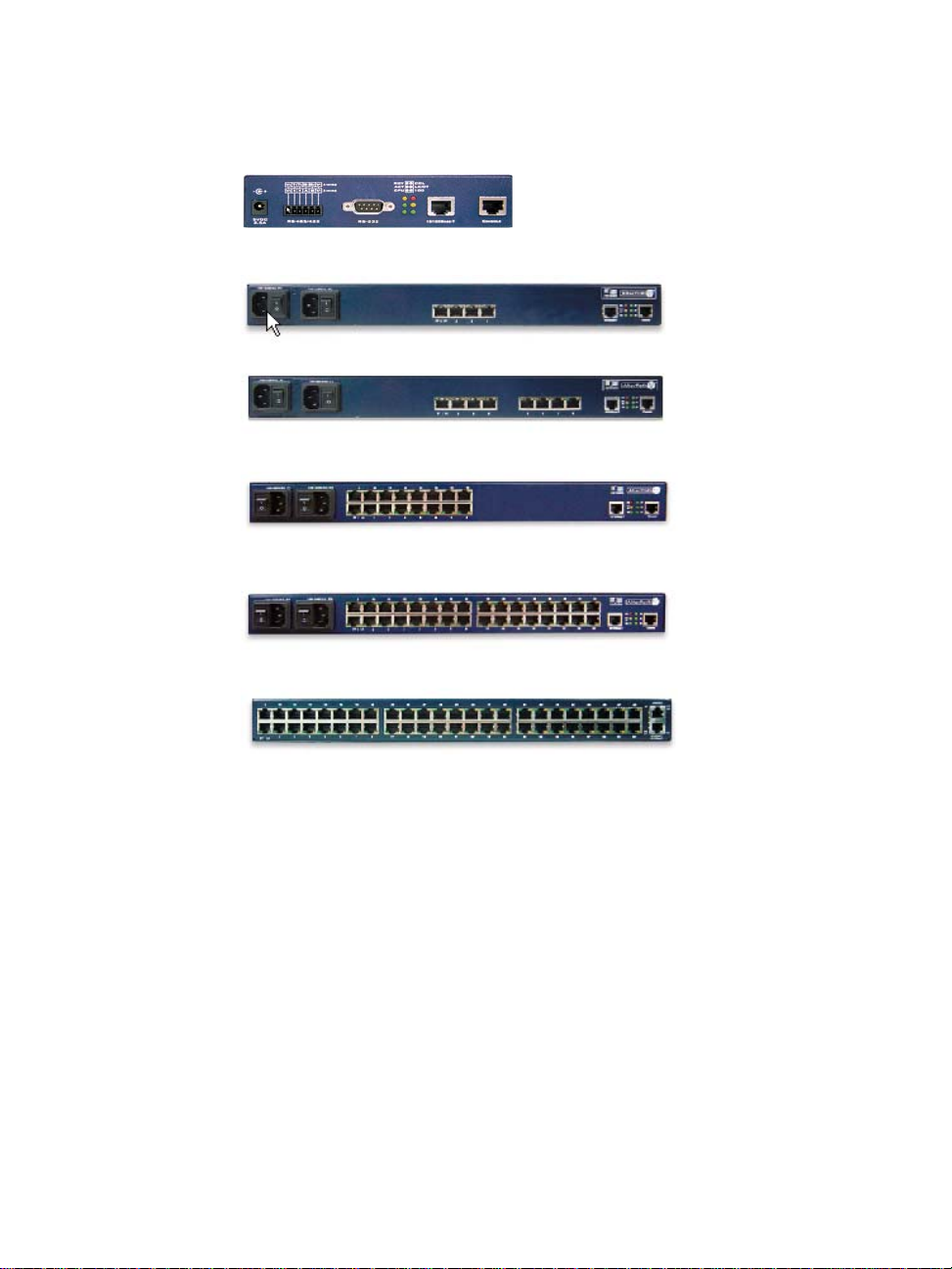
The figure below shows AlterPath ACS1 through ACS48.
1: Introduction
AlterPath Console Server User Manual 7
Page 14
1: Introduction
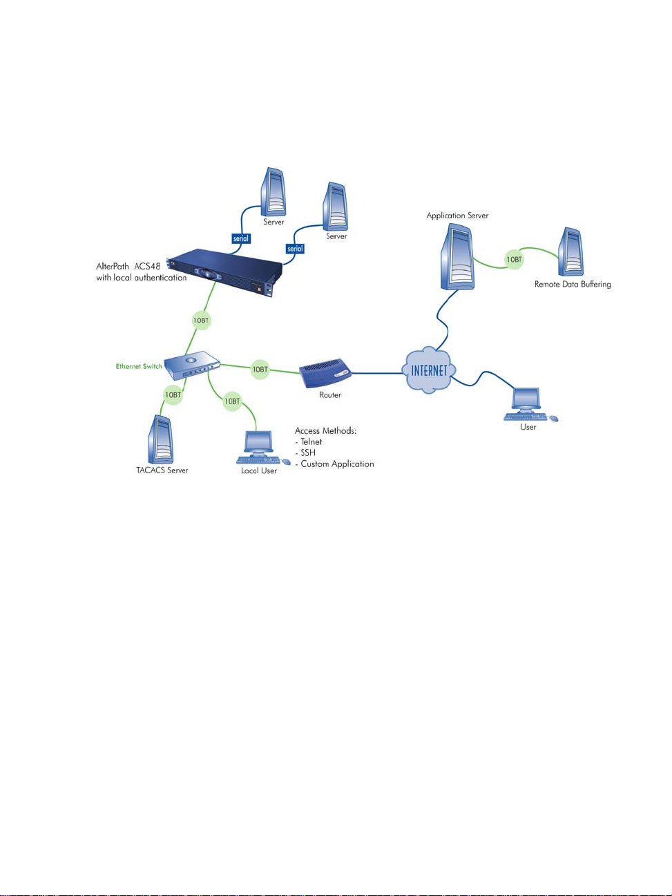
ACS Setup Diagram
The diagram below shows a typical setup of the AlterPath Console Server.
8 AlterPath Console Server User Manual
Page 15

Chapter 2
Installing the ACS
Chapter 2 - Installing the ACS
This chapter presents the procedures for installing and setting up the ACS,
and is organized as follows:
• Package Contents
• Rack Installation
• Installation and Configuration Process
For configuration procedures using vi or CLI, refer to the
ACS Reference Guide.
Package Contents
There are six models of the AlterPath Console Server based on the number of
serial ports:
•ACS48
•ACS32
•ACS16
•ACS8
•ACS4
•ACS1
All models come with either a single (A/C or VDC) or double (A/C or -48
VDC) power supply.
9 AlterPath Console Server User Guide
Page 16
2: Installing the ACS
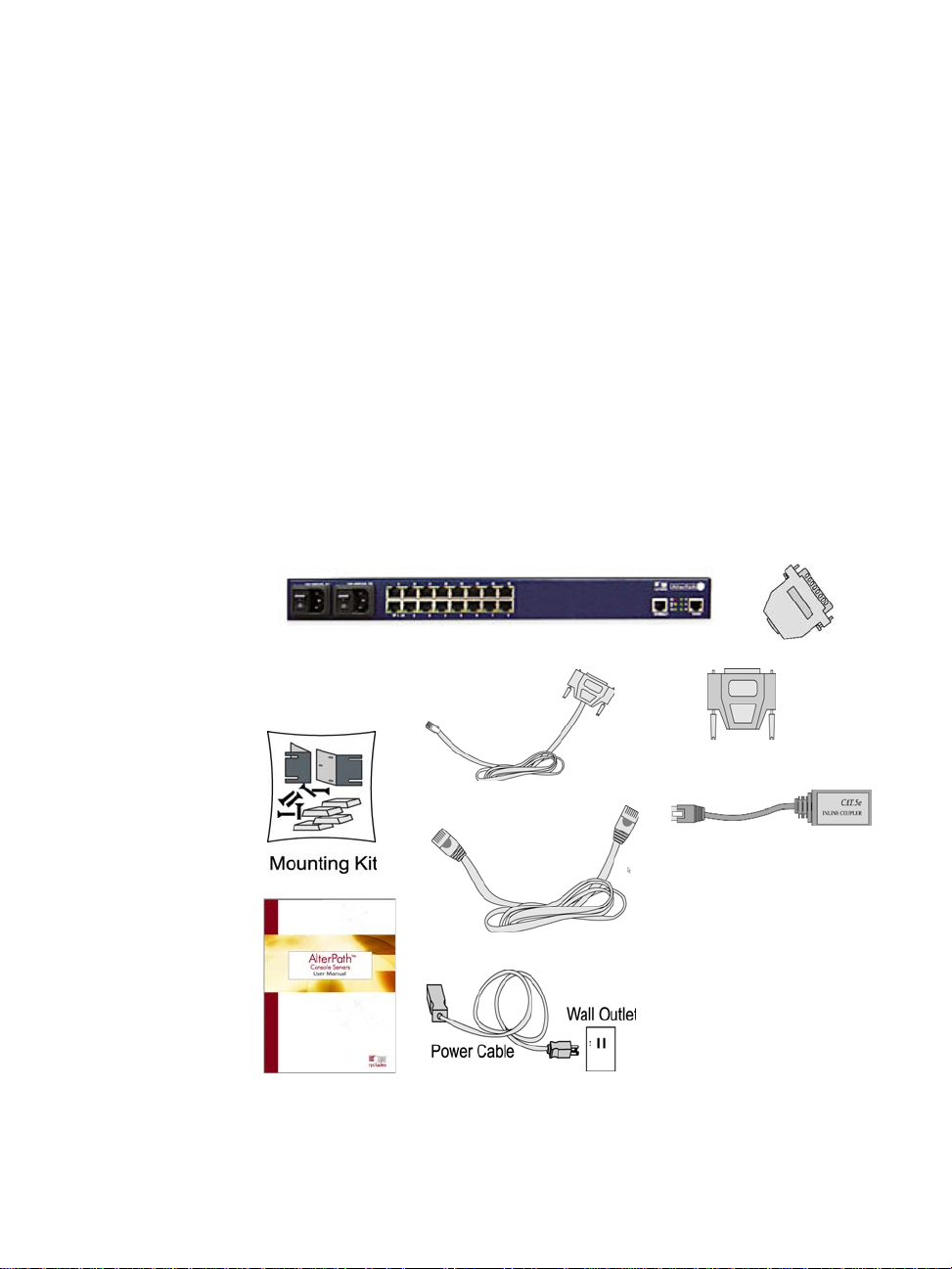
Package Contents: ACS4 through ACS48
Typically, the product package for ACS4 through ACS48 contains the
following:
• ACS Box
• Power Cable(s)
• ADB0017 - DB25F Console Adapter
• ADB0025 - DB25M Console Adapter
• ADB0036 - DB9F Console Adapter
• ADB0039 - Sun/Netra Adapter
• CAB0018 - RJ45 CAT-5 Cable
• CAB0025 - DB25M Straight-Through Cable
• CON0071 - DB25F Loopback Connector
• Rack-Mounting Kit
• ACS User Manual and ACS QuickStart Guide
• ACS Reference Manual CD
10 AlterPath Console Server User Guide
Page 17
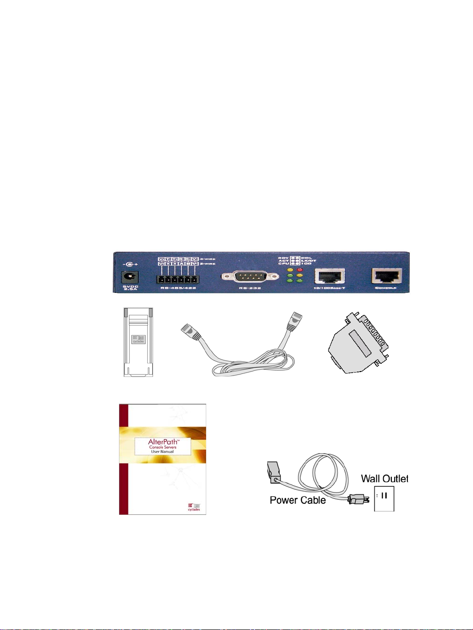
Package Contents: ACS1
The ACS1 Package contains the following:
• ACS1 Box
• Power Cable
• Power Supply +5V / 2.5A
• CAB0042 - DB25F / DB9F Cross Cable
• CAB0018 - RJ45 / RJ45 CAT5 Cable
• CON0071 - DB25F Loopback Connector
• ADB0036 - RJ45 to DB9F Adapter
• CON0093 - DB9F to DB25M Connector
• ACS User Manual and ACS QuickStart Guide
• ACS Reference Manual CD
2: Installing the ACS
AlterPath Console Server User Guide 11
Page 18
2: Installing the ACS
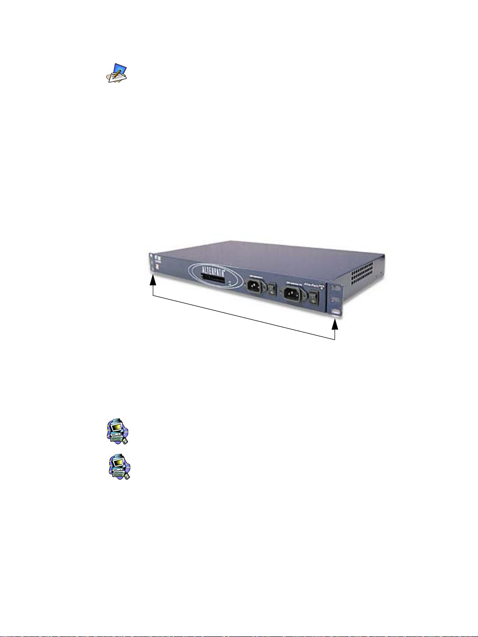
Rack Mounting the ACS
To rack-mount and connect the ACS to your network, perform the following
steps:
1. Install the brackets onto the front corners of the box using a screw driver
Although the ACS unit in the figures are shown with a dual power supply (A/C
or -48VDC), some models may have a single power supply. The single power
units will have just one power cable.
(ACS48 supports -48VDC.)
and the screws and bolts provided with the mounting kit.
brackets
2. Mount the ACS box in a secure position.
Refer to Appendix B: Safety Guidelines section of this manual to ensure
safety .
Important! Install your AlterPath Console Server near the power
managed equipment and in an easily accessible location.
Important! Install the AlterPath Console Server in a location where
there is an adjacent and accessible wall socket outlet.
3. Proceed to the Installation and Configuration section of this chapter.
12 AlterPath Console Server User Guide
Page 19

System Requirements
To configure the ACS, Cyclades recommends any of the following hardware
specifications:
• Workstation with a console serial port or,
• Workstation with Ethernet and TCP/IP topology or,
• Cyclades AlterPath Manager.
The hardware connectivity required for each configuration method:
Hardware Connectivity Configuration Method
Workstation, Hub Ethernet Cables. Web browser, vi, Wizard, or CLI
Console, Console Cable (constructed from RJ45
straight-through cable + adapter
Workstation, Hub Ethernet Cables.
This manual is designed primarily for web browser users. If you will use vi,
the wizard (CLI version) or CLI, refer to the ACS Reference Guide.
2: Installing the ACS
vi, Wizard, or CLI.
To install ACS with AlterPath Manager, refer to the AlterPath
Manager Manual and configure the device using the Manager.
Default Configuration Parameters
• DHCP enabled (if there is no DHCP Server, IP for Ethernet is
192.168.160.10 with a Netmask of 255.255.255.0)
• CAS configuration
• Socket_server in all ports (access method is telnet)
• 9600 bps, 8N1
• No Authentication
AlterPath Console Server User Guide 13
Page 20

2: Installing the ACS
Pre-Install Checklist
Before you install and configure the ACS, ensure that you have the following:
Root Access You will need Root Access on your local UNIX
HyperTerminal, Kermit, If you are using a PC, ensure that HyperTerminal
or Minicom is set up on your Windows operating system. If
IP Address of: You will need to locate the IP address of your PC
PC or terminal, or workstation, the ACS, and the machine that
AlterPath Console Server, resolves names on your network. Your Network
NameServer, and Gateway Administrator can supply you with these. If there
Network Access You must have a NIC card installed in your PC to
machine in order to use the serial port.
you have a UNIX operating system, you will be
using Kermit or Minicom.
is outside access to the LAN that the ACS will be
connected with, you will need the gateway IP
address.
provide an Ethernet port, and have network
access.
Java 2 JRE You must have Java 2 Runtime Environment
(JRE) version 1.4.2 (which can be found at http://
java.sun.com/) installed on your PC with your
browser acknowledged to use it.
Ensure that the browser you are using
acknowledges the Java version by following the
procedures given in Appendix C: Supported
Browsers and JRE.
14 AlterPath Console Server User Guide
Page 21

Installation and Configuration Process
The installation and configuration process is divided into six distinct tasks:
• Task 1: Install ACS and connect to the network.
• Task 2: Configure the network settings (using the console port).
• Task 3: Configure ACS by using the web in Wizard Mode.
• Task 4: Test Configuration.
• Task 5: Customize configuration by using the web in Expert Mode.
• Task 6: Save Changes.
You can configure ACS using the command line interface alone.
See the ACS Reference Guide to configure ACS in CLI.
Task 1: Install ACS and connect to the network
1. Plug the power cable into the ACS.
(When using an external power source. Optional.) Insert the female end of
the black power cable into the power socket on the ACS and the 3-prong
end into a wall outlet.
2: Installing the ACS
DANGER!
grounded power source. The cable is equipped with a 3-prong plug to hel p
ensure proper grounding. Do not use adapter plugs or remove the grounding
prong from the cable. If you use an extension cable, use a 3-wire cable with
properly grounded plugs.
IMPORTANT!
receptacle protected by an appropriate, listed circuit breaker
To help prevent electric shock, plug the ACS into a properly
The AlterPath Console Server must be plugged into a
.
2. Connect the console cable.
Construct a Console Cable out of the RJ-45 straight-through cable and the
appropriate adapter provided in the product box. (All adapters have an RJ-45
connector on one end, and either a DB25 or DB9 connector on the other end,
male or female). Connect this cable to the port labeled “Console” on the ACS
with the RJ-45 connector end, and connect the adapter end to your PC’s
available COM port.
AlterPath Console Server User Guide 15
Page 22

2: Installing the ACS
3. Connect to the Network.
Task 2: Configure network settings
This step is necessary to make ACS visible on the network. The configuration
can be done using the console port of the Cyclades ACS or via the network
using the default network settings.
Initial Configuration Using the ACS Console Port
1. Install and launch your serial communication software (e.g.,
The modem cable is not necessary for a standard installation and
configuration. Use it when the configuration is complete and you
want to access the box remotely thro ugh a serial port.
Connect the ACS network port to the Ethernet hub switch.
HyperTerminal, Kermit or Minicom).
You can obtain the latest update to HyperTerminal from:
http://www.hilgraeve.com/htpe/download.html.
If you are using a PC, use HyperTerminal to perform the initial
configuration of the ACS directly through your PC’ s COM port connected
with the ACS. HyperTerminal, which comes with Windows 95, 98, Me,
NT, 2K, and XP is often located under Start > Program > Accessories.
HyperTerminal emulates a dumb terminal when your PC connects to the
serial port (console port) of the ACS.
2. Select available COM port.
In HyperTerminal (Start > Program > Accessories), select File >
Properties, and click the Connect To tab. Select the available COM port
number from the Connection dropdown list box.
3. Configure COM port using the following values:
• 9600 bps
• 8 data bits
• No parity
• 1 stop bit
• No flow control
16 AlterPath Console Server User Guide
Page 23
2: Installing the ACS
4. Power on the ACS.
Click OK on the Properties window.
You will see the ACS booting on your screen. After it finishes booting,
you will see a login prompt.
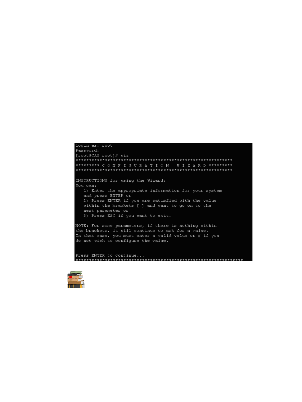
5. Connect COM Port to the ACS Console.
Login as root, and enter the default password, tslinux.
6. Type in: wiz
As shown in the sample screen below, the system brings up the
configuration wizard banner and begins running the wizard. Follow the
system prompts to either accept the default values or enter them manually .
For the procedure on how to configure the ACS from wiz to support
Kerberos tickets, r e fer to the ACS Reference Guide.
7. Proceed to Task 3.
AlterPath Console Server User Guide 17
Page 24

2: Installing the ACS
After the initial configuration, you can configure the network further by using
any of the following methods:
• Web Interface
• Command Line Interface via SSH
• AlterPath Manager, if installed in your network
Task 3: Configure via Web Wizard
Proceed to Chapter 4: Configuring the Web Interface, and complete the
procedure for configuring ACS in Wizard Mode.
Task 4: Test Configuration
Log in as a regular user and connect to a port.
Check the other features (e.g., Data Buffering, Management, etc.) as
discussed in Chapter 3: Using the ACS.
To use the ACS web management interface, ask your System
Administrator for the IP address. By default, ACS uses the IP
address provided by the DHCP server. If your network doesn’t have
DHCP, then ACS will default to 192.168.160.10. Configure your
ACS to connect to this address and run the web interface.
To create new users, see Wizard Mode Step 3: Access (page 4-10) of
Chapter 4: Configuring the Web Interface.
Task 5: Configure the web interface in Expert Mode
Return to Chapter 4: Configuring the Web Interface and continue with
configuration using the Expert Mode.
Task 6: Save Changes
Click on the Apply Changes button located on the bottom of the ACS Web
Configuration screen when done to save your configuration to Flash.
18 AlterPath Console Server User Guide
Page 25

Chapter 3
Using the Web Interface
Chapter 3 - Using the Web Interface
This chapter presents the methods for accessing serial ports and the basic
operations for using ACS. Addressed to the ACS end user, the chapter is
divided into the following topics:
• Using the Web Interface
• Using the Command Line Interface
• Using Telnet
• Using the TS Menu
• Power Management
Using the Web Interface
Refer to Appendix B for a description of the web requirements for
connecting to a serial port.
To use the web interface to connect to a serial port, follow the following
procedure:
1. Connect your web browser to the ACS by typing in the Console
Access Server’s IP address (e.g., https://10.10.10.10) provided to
you by your system administrator in the address field of your
internet browser.
2. Press Enter.
19 AlterPath Console Server User Manual
Page 26
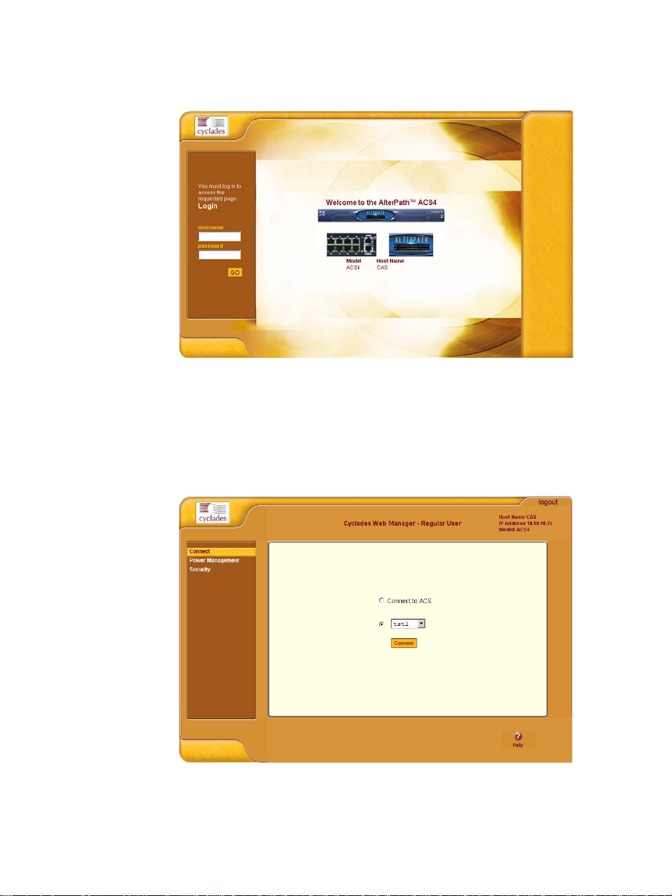
3: Using the Web Interface
The system brings up the ACS Web Application Login Window:
3. To log in, type in your username and password as provided to you
by your system administrator.
4. From the top menu bar, select Applications; from the left menu panel,
select Connect
The system brings up the Port Selection form:
.
20 AlterPath Console Server User Manual
Page 27
3: Using the Web Interface
5. T o connect to a port (by default, the radio button is already selected
for connecting to a port), select from the drop down menu the port
to which you wish to connect, and then click on Connect.
- OR To connect to the ACS box, select the radio button for Connect to
ACS Box, and then click on Connect.
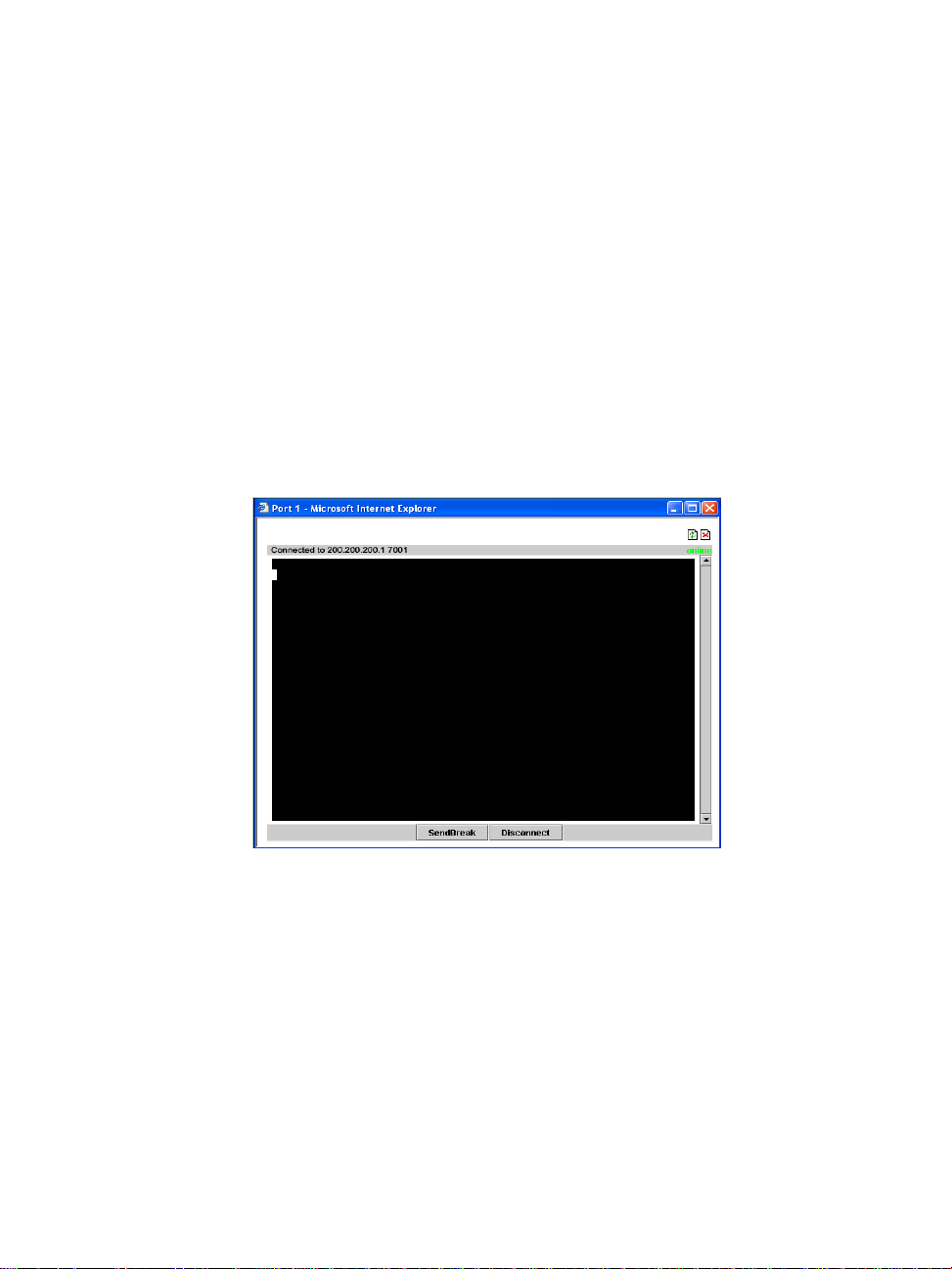
Depending on your selection, the system either opens a Java
connection to the port selected, or launches an SSHv2 connection to
the ACS box.
In the sample screen below, the system dispalys a Java window
after connecting to a chosen server.
Using the Command Line Interface (CLI)
Operating the terminal varies according to whether the selected port is
configured for Telnet access or for SSH access.
To log in, see the log in instructions for Telnet or SSH in the next section of
this chapter.
Click in the terminal window and start entering commands.
AlterPath Console Server User Manual 21
Page 28

3: Using the Web Interface
To send a break to the terminal, click on the SndBreak button.
The upper right hand corner of the browser (Java window) shows two icons:
Refresh and Disconnect.
Select the left icon to refresh or reconnect to the server; select the right icon to
end the session or disconnect from the Java window.
Logging onto the Terminal
Telnet Access
To open a telnet session to a serial port, enter the following command:
telnet <hostname or IP address> <TCP port number>
Press ENTER
Where:
<hostname> is the hostname configured in the workstation where the telnet
client will run (through /etc/hosts or DNS table). Or it can just be the IP
address of the AlterPath ACS (Ethernet's interface) as configured by the user
or as learned from DHCP.
<TCP port number> is the number associated to the serial port. The factory
values, 7001 corresponds to serial port 1, 7002 to serial port 2 and so forth,
and 3000 is a pool with all serial ports.
T o close the telnet session, just press the telnet hot key configured in the telnet
client application (usually it's "Ctrl-]").
SSH Access
Secure Shell (SSH) is a command interface and protocol often used by
network administrators to connect securely to a remote computer. SSH
replaces its non-secure counterpart rsh and rlogin. There are two versions of
the protocol, ssh and ssh2. The AlterPath Console Server offers both.
22 AlterPath Console Server User Manual
Page 29

To ope n a ss h session to a serial port or the next free serial port from a pool,
issue the command:
ssh -l <username>:<server> <hostname or IP address>
Where:
<username> is the user configured to access that serial port. It is present either
in the local CAS database or in a Radius/Tacacs/LDAP/Kerberos, etc
database.
<Server> can be just the TCP port number assigned for that serial port (7001,
7002, etc), (3000, etc), the alias for the server connected to that serial port.
<hostname or IP address> is the hostname configured in the workstation
where the ssh client will run (through /etc/hosts or DNS table). It can also be
just the IP address of the AlterPath ACS (Ethernet's interface) configured by
the user or learned from DHCP.
T o exit the ssh session, press the hot key configured for that ssh client (usually
"~.").
ts_menu Access
3: Using the Web Interface
To a ccess the serial port (telnet or ssh) using the ts_menu, login to the CAS
unit and, after receiving the shell prompt, type in:
ts_menu
If configured, the menu will display the servername otherwise it defaults to
the serial port number. See the sample menu below:
Serial Console Server Connection Menu for your Master
Terminal Server
1 ttyS1 2 ttyS2 3 ttyS3 4 ttyS4
5 ttyS5 6 ttyS6 7 ttyS7 8 ttyS8
Type 'q' to quit, a valid option[1-8], or anything else
to refresh:
AlterPath Console Server User Manual 23
Page 30

3: Using the Web Interface
Closing the session from ts_menu (from the console of your unit)
1. Enter the escape character.
The escape character is shown when you first connect to the port.
In character/text Mode, the Escape character is ^] (caret and bracket, for
telnet) or ~. (tilde and period, for SSH).
After entering the escape character, the following menu is shown:
Console escape. Commands are:
l go to line mode
c go to character mode
z suspend telnet
b send break
t toggle binary
e exit telnet
2. Press “e” to exit from the session and return to the original menu.
Select the exit option and you will return to the shell prompt.
Closing the session from ts_menu
From Telnet
You have to be sure that a different escape character is used for exiting your
telnet session; otherwise, if you were to exit from the session created through
the ts_menu, you will close your entire telnet session to your unit.
To do this, when you first telnet to your unit, use the “-e” option.
Example: to set Ctrl-? as the escape character, type:
telnet -e ^? 192.168.160.10
To exit from the session created through the ts_menu, just follow Step 1 from
above. To exit from the entire telnet session to your unit, type the escape
character you had set.
From SSH
If you use SSH to make the first connection to the ACS, then the escape
character for each session becomes: ~~. (tilde, tilde, period)
24 AlterPath Console Server User Manual
Page 31

Power Management
The Power Management forms (Application > Power Management >
Outlets Manager or View IPDUs Info) allows you to manage the power
outlets on the Cyclades AlterPath PM family of Intelligent Power Distribution
Units (IPDUs) or view information about the IPDUs connected to the ACS.
The Outlets Manager form is used to power remote machines on and off,
check the status and lock the power outlet in the on or off state to prevent
accidental changes. The View IPDUs Info is used to view information about
the status of the IPDU units.
For information on how to configure Power Management, refer to the Power
Management section of Chapter 4: Configuring the Web Interface.
3: Using the Web Interface
AlterPath Console Server User Manual 25
Page 32

3: Using the Web Interface
Security
The Security form allows you to change your password.
1. From the menu panel, select Security.
The system brings up the Security form.
2. From the Security form enter your current password and new
password (twice).
3. Select OK when done.
4. Log out and log in using your new password to verify your
password change.
26 AlterPath Console Server User Manual
Page 33

Chapter 4
Configuring the Web Interface
Chapter 4 - Configuring the Web Interface
This chapter presents the procedures for configuring ACS using the web
interface. It is organized as follows:
Overview
Logging In
ACS Web Interface: GUI Elements
Configuring in Wizard Mode
Step 1: Network Settings
Step 2: Port Profile
Step 3: Access
Step 4: Data Buffering
Step 5: System Log
Configuring in Expert Mode
Applications
Network
Security
Ports
Administration
Overview
This chapter addresses the System Administrator who is responsible for
configuring the ACS web interface and its users. For information on how to
configure ACS using vi or Command Line Interface (CLI), please consult the
ACS Reference Guide.
The ACS web configuration interface provides two modes of operation:
Wizard and Expert. The organization of the chapter follows, in sequential
order, the two modes and the menu selections available from each mode.
If you are a regular user, refer to Chapter 3: Using the Web Interface.
27 AlterPath Console Server User Manual
Page 34

4: Configuring the Web Interface
Logging In
1. Connect your internet browser to the Console Server by typing in the
Console Access Server’s IP address (e.g., http://10.0.0.0) in the browser’s
address (URL) field.
T o determine the IP addr ess of the ACS, switch on the ACS connected
to the Ethernet where there is a DHCP server. When you inquire,
based on the MAC address (the 12-digit hexadecimal number located
at the bottom of the ACS unit), the server will provide the appropriate
IP address. If there is no DHCP server, use the default static IP
address that is pre-configured in the ACS: 192.168.160.10.
For more detailed information, see Chapter 2.
The system brings up the AlterPath ACS Login page:
2. Log in as root and type in the Web root password configured by the Web
server.
The system brings up the ACS Web management page.
28 AlterPath Console Server User Manual
Page 35

4: Configuring the Web Interface
If another administrator is using the system, the following message
appears:
3. Click on the appropriate radio button and then click on the Apply button.
IMPORTANT: T ake note of this login pr ocedur e. All subsequent online
procedures in this chapter assume that you are already logged in.
AlterPath Console Server User Manual 29
Page 36

4: Configuring the Web Interface
ACS Web Interface: GUI Elements
The ACS web interface operates on two modes:
• Wizard
•Expert
Wizard Mode
The wizard is designed to simplify configuration by providing users the
default parameter values. The system will prompt you for the necessary fields,
give instructions during the process and, in some cases, populate the fields
automatically.
Designed for the novice, the wizard mode allows you to perform the basic
configuration necessary to set up ACS and users in the quickest possible way.
When you log in to ACS, the system brings up by default the Expert Mode
screen. To change to the Wizard Mode, click on the button located in the left
bottom corner of the screen labeled Wizard.
User Entry Panel or Form
Logout button and IP/Hostname Info
Menu
Panel
Control Buttons
30 AlterPath Console Server User Manual
Unsaved Data
Indicator
Page 37

Shown above is a typical page of the ACS web interface in Wizard Mode. The
user entry panel or form varies depending on the selected menu item. The
ACS uses forms and dialog boxes (i.e., pop-up windows that prompt you for
an answer or command) for data entry.
Expert Mode
Designed for advanced users, this is the default mode when you log in the
ACS. You can also change to this mode by clicking the Expert button at the
bottom of the menu panel switches the web interface from Wizard to Expert
Mode. Shown below is a typical ACS screen in Expert Mode. A main
difference between the two modes is the addition of a top menu bar in the
Expert Mode to support a wider array of menu choices.
The top menu bar is the primary menu; the left menu panel is the secondary
menu. Based on what you select from the top menu bar, the left menu
selections will change accordingly..
4: Configuring the Web Interface
Menu
Panel
Form Tabs
Control Buttons
Top Menu Bar
User Entry Panel
or Form
Logout button and
IP/Hostname Info
Unsaved Data
Indicator
AlterPath Console Server User Manual 31
Page 38

4: Configuring the Web Interface
Occasionally, an Expert Mode menu selection will comprise multiple forms
(such as the one shown above). These forms are identified by their tabs. Select
the tab to access the desired form.
Button Functions
The control buttons located on the bottom of the ACS Web Configuration
window provide you the following functions for operating the interface.
Button Name Use this button to:
Wizard / Expert Wizard / Expert Switch the ACS Web Configuration
Help? Invoke the online help sub window which provides
Back Traverse to the previous form (i.e., the form
Try Changes T est or run the system based on the settings from the
Cancel Changes Cancel your changes or reverts back to the original
Apply Changes Save your changes to the ACS Flash card.
Next Traverse to the next form (i.e., the form succeeding
Screen to either Expert or Wizard Mode. The Expert
Mode is the default mode; in this mode, the Wizard
button is visible and vice versa.
help information relating to the current form.
preceding the current form as it appears in the
menu).
current form without having to save the
configuration.
configuration values.
the current form as it appears in the menu).
Saving Your Configuration
The Unsaved Changes indicator on the lower right hand corner of the ACS
web configuration window serves to remind you that you have made a
configuration entry or change which has not been saved.
32 AlterPath Console Server User Manual
Page 39

4: Configuring the Web Interface
Unless you do not need to save your configuration, be sure to select the
Apply Changes button to ensure that your changes are saved to Flash.
AlterPath Console Server User Manual 33
Page 40

4: Configuring the Web Interface
Configuring in Wizard Mode
As shown in the menu, the Wizard Mode configuration is composed of five
steps:
Step 1: Network Settings
Step 2: Port Profile
Step 3: Access
Step 4: Data Buffering
Step 5: System Log
Step 1: Network Settings
To configure the network settings for the ACS, follow the following steps:
1. From the main menu of the web interface, select Step 1: Network
Settings.
The system brings up the DHCP page (shown below). By default, the
DHCP checkbox is check marked, which means that the system is
already configured to use the DHCP server.
34 AlterPath Console Server User Manual
Page 41

4: Configuring the Web Interface
2. If you are using DHCP, proceed to Step 2: Port Profile; if not, click on
the checkbox to deselect DHCP and enter your network settings
manually.
The Network Settings entry fields should appear as follows:
3. Type in the network information in the corresponding entry fields, and
then select Apply Changes.
If the meaning of a field is unclear, select the Help button for a definition
of the field.
4. Select the Next button OR proceed to Step 2: Port Profile section.
AlterPath Console Server User Manual 35
Page 42

4: Configuring the Web Interface
Step 2: Port Profile
The Port Profile configures your Console Access Profile (CAS), defining the
protocol and type of command line interface you will use to access the ACS.
The Port Profile controls the speed, data size, parity, and stop bits of all ports.
It sets the flow control to hardware, software, or none; and sets the DCD
signal and tty after the system establishes a socket connection to that serial
port.
In Wizard mode the system assumes that all devices will be connected at the
same parameter values.
If you need to configure different values to specific devices, then you
must click on the Expert mode button and select Ports > Physical
Ports to enter these values.
1. From the main menu of the web interface, select Step 2: Network
Settings.
The system displays the Port Profile form:
2. From the Port Profile form, complete the necessary fields.
36 AlterPath Console Server User Manual
Page 43

4: Configuring the Web Interface
Field Name Definition
Connection Protocol The method you will use to access the serial ports.
Cyclades recommend SSH to ensure that all data and
authentication information are encrypted. Other
options are Telnet and Raw Data (for un-negotiated
plain socket connections).
Flow Control The method of flow control used by the attached
devices (Hardware, Software, or None).
Baud Rate The serial speed on each console port, which should
match the equipment you will connect to. The
recommended Baud Rate is 9600.
Data Size Number of data bits used by the attached devices (5,
6, 7 or 8).
Parity Parity used by the attached devices (None, Odd, or
Even).
Stop Bit s Number of stop bits used by the attached devices.
Authentication Req’d Selecting this checkbox sets the system to require
authentication to access the ports. This is done in the
local database in the ACS.
If you require port authentication, then you must add users through
Wizard Step 3: Access.
To configure other authentication methods (e.g., LDAP, RADIUS,
TACACS), select the Expert button to switch to Expert Mode and
select: Security > Authentication.
3. Select Apply Changes to save configuration to Flash.
4. Select the Next button or proceed to the next section, Step 3: Access.
AlterPath Console Server User Manual 37
Page 44

4: Configuring the Web Interface
Step 3: Access
The Wizard configuration of the Access form enables you to configure the
general access rights of users and groups to the ACS or systems which ACS
controls.
To grant users access to specific ports, switch to the Expert Mode,
then go to Security > Users and Groups.
From this window, you can:
• Change a User Password
• Add a user
• Delete a user
1. If you haven’t opened the Access Form, from the menu panel, select Step
3: Access.
The system brings up the Access form:
2. To complete your User Access configuration, proceed to the appropriate
subheadings of this section: Changing a User Password, Adding a User,
or Deleting a User.
38 AlterPath Console Server User Manual
Page 45

4: Configuring the Web Interface
Changing a User Password
If you haven’t changed your root administration password, now is
the time to change it using the Change User Password dialog box.
1. From the Users scrollable field box of the Access window , select the user
whose password you want to change, and then select the Change
Password button.
The system brings up the Change User Password dialog box:
2. Type in the new password in the two entry fields of the dialog box, and
then click on the OK button.
AlterPath Console Server User Manual 39
Page 46

4: Configuring the Web Interface
Adding a User
1. If you haven’t opened the Access form, select Step 3: Access from the
menu panel.
The system brings up the Access form.
2. From the Access form, select the Add button.
The system brings up the Add User dialog box:
3. Enter the necessary User information into the following fields:
Field Name Definition
User Name Name of the ACS user.
Password Password to be used by the user to access ACS.
Repeat Password Re-type the password.
Group Select the user group to which the user belongs.
There are two default groups with the following
associated access rights:
Admin (Read/Write)
Regular User (Read Only)
40 AlterPath Console Server User Manual
Page 47

4: Configuring the Web Interface
Field Name Definition
[dropdown list] Select whether the user of this group is a NonBio
or a BioUser. The NonBio group, is the correct
choice for regular users. The BioUser group
should only be selected if authentication will be
made through the Cyclades AlterPath Bio
(biometric authentication).
Shell Text string you wish to use as part of the shell
prompt for the current user.
Comments Comments about the current user.
To define a new group, select the Expert button to switch to the
Expert Mode, and then select Security > Users and Groups.
4. Select the OK button when done.
5. From the bottom of the main window, select the Apply Changes button.
Deleting a User
1. From the Users scrollable field box of the Access form, select the user
that you wish to delete.
2. Select the Delete button.
3. Select Apply Changes.
For information on how to configure users and groups, see Users and Groups
under configuring ACS in expert mode.
AlterPath Console Server User Manual 41
Page 48

4: Configuring the Web Interface
Step 4: Data Buffering
This step configures the data buffering file and mode for all ports that ACS
controls.
You can set data buffering to be done in local files or in remote files through
NFS. When using remote files, the remote server’s disk/partition space
imposes a limitation and the data is kept in linear (or sequential) files in the
remote Server. When using local files, the size of the available RAMdisk also
imposes a limitation. You can have data buffering done in file, syslog or both.
If you accept the default configuration values for data buffering, skip this step
and proceed to Step 5: System Log. Do not click on the Enable Data
Buffering checkbox.
1. From the menu panel, select Step 4: Data Buffering.
The system brings up the Data Buffering form:
2. Select the Enable Data Buffering checkbox, if unselected.
The system invokes the Data Buffering input fields.
42 AlterPath Console Server User Manual
Page 49

4: Configuring the Web Interface
3. Complete the input fields as follows:
Field Name Definition
Destination Destination of the buffer files: Local (i.e.,
Ramdisk) or Remote.
Mode If you selected Local destination, choose the file
sort mode. Select Linear for sequential files,
Circular for non-sequential files.
File Size (Bytes) If you selected Local destination, the value for this
field cannot be zero.
Record the time stamp... Commands the system to include a time stamp in
the buffer.
Data Buffering file Name of the buffer file.
Show Menu Defines what you want to show in the menu of the
buffer file. Select from: Show all options, No,
Show data buffering file only, and Show without
the erase options.
4. If you selected Remote from the Destination field, type in the NFS File
Path from the resulting form (i.e., specify the NFS mount point. The NFS
server must be already configured, and the mount point exported):
5. Click on the Apply Changes button.
AlterPath Console Server User Manual 43
Page 50

4: Configuring the Web Interface
The system can filter messages based on their content and perform an action
(e.g. to send an e-mail or pager message). To configure data buffering to send
a notification alarm, you must use the Notifications form (Go to Expert
Mode: Administration > Notifications).
Step 5: System Log
The System Log form allows you to configure one or more syslog servers to
receive syslog messages that are generated by the ACS. The ACS sends
syslog messages to all syslog servers that are defined here.
To configure syslog with data buffering features for specific ports,
switch to the Expert Mode, and then go to Ports > Physical Ports >
Data Buffering.
1. From the menu panel, select System Log.
The system brings up the System Log form:
2. From the System Log form, select the Syslog facility number that the
ACS will use to send out syslog messages.
44 AlterPath Console Server User Manual
Page 51

3. To add a new syslog server, type in the IP address in the New Syslog
Server field, and click Add. (Repeat step for as many syslog servers you
need to add.)
OR
4. To delete a syslog server, select the Syslog server to be deleted from the
Syslog Servers scrollable list box, and then click Delete.
5. Click on the Apply Changes button at the bottom of the main panel.
Configuring in Expert Mode
This section presents the procedures for configuring the ACS web interface in
Expert Mode. This mode is designed for the advanced user who needs to
configure the ACS beyond the capabilities of the basic wizard mode.
As indicated in the top menu bar, there are five additional areas of ACS
configuration in Expert mode:
• Applications
•Network
• Security
•Ports
• Administration
4: Configuring the Web Interface
Expert Mode Menu
Each top menu option provides additional side menu selections. Their
functions are as follows:
Applications
Menu Selection Use this menu to:
Connect Select and connect to a port.
Power Management View and edit IPDU settings.This menu comprises
five tabbed forms: Outlets Manager, View IPDUs
Info, Users Manager, Configuration, and Software
Upgrade.
AlterPath Console Server User Manual 45
Page 52

4: Configuring the Web Interface
Menu Selection Use this menu to:
Terminal Profile Menu Create command menu for a terminal (i.e., CLI or
Most of the fields for each form are defined in the procedure. For a
more detailed definition of these field names or terms, however, refer
to the Glossary of this manual.
Network
Menu Selection Use this menu to:
Host Settings Configure host connections, including: Ethernet Port
Syslog Define the Syslog Servers to enable system logging.
PCMCIA Management Enable the insertion or ejection of PCMCIA cards;
VPN Connections Configure IPsec tunnels to establish a secure
SNMP Daemon Settings Configure the SNMP server to manage complex
Services Define or activate the method of access (i.e., Telnet,
Firewall Configuration Configure static IP tables
Host Table View table of hosts; create, edit, and delete hosts.
Stat ic Rout es View, create and delete routes from the table.
VI).
connections, DNS Service, and Name Service
Access.
configure the type of access and connection (e.g.,
Modem, ISDN, Ethernet) to ACS.
connection between ACS and a security gateway
machine.
networks.
SSH, SNMP, Client, or NTP).
Security
Menu Selection Use this menu to:
Users and Groups Create/edit users and groups, establish/change their
passwords, access rights and privileges.
Active Port Sessions View the status of all active port sessions.
46 AlterPath Console Server User Manual
Page 53

4: Configuring the Web Interface
Ports
Menu Selection Use this menu to:
Physical Ports Modify ports settings for individual or all ports.
Physical Ports is composed of five configuration
forms as identified by their tab names: General,
Access, Data Buffering, Multi-User,
Power Management and Other.
Virtual Ports Add, edit or delete port slaves.
Port Status Shows the current status of each port. The
information provided here are: RS232 Signal Status
and user connected to each port.
Administration
Menu Selection Use this menu to:
System Information View summary information about the system (e.g.,
Kernel, CPU, memory, etc.).
Notifications Configure the system to deliver alarm notification by
email, pager, or snmp trap; define alarm triggers; set
data buffering to send notification.
Time/Date Set the unit’s date and time.
Boot Configuration Defines the settings for loading the operating system
in the event that the ACS fails to boot successfully.
Backup Configuration Use a FTP server to save and retrieve your ACS
configuration; use a storage device to store your
configuration.
Upgrade Firmware Upload/upgrade new fi rm ware.
Reboot Reboot the ACS system.
AlterPath Console Server User Manual 47
Page 54

4: Configuring the Web Interface
Applications > Connect
The Connect form, which launches a Java browser, is used to:
• Connect to the ACS box. The connection type is always SSHv2.
• Connect to a console port based on what port you select from the drop
down menu. The connection type depends on how your ACS is configured.
1. From the top menu bar, select Applications; from the left menu panel,
select Connect.
The system invokes the port selection form:
2. T o connect to a port (by default, the radio button is already selected
for connecting to a port), select from the drop down menu the port
to which you wish to connect, and then click on Connect.
- OR -
To connect to the ACS box, select the radio button for Connect to
ACS Box, and then click on Connect.
Depending on your selection, the system either opens a Java connection to the port selected, or launches an SSHv2 connection to the
ACS box.
48 AlterPath Console Server User Manual
Page 55

Applications > Power Management
ACS allows you to remotely manage all Intelligent Power Distribution Units
(IPDUs) connected to the ACS. Power management configuration comprises
five tabbed forms:
Form Title Use this form to:
Outlets Manager Switch on/off and lock/unlock outlets.
View IPDUs Info View IPDU information by ports and slaves. The
information form provides real-time, global, current
monitoring of all connected devices.
Users Manager Add or delete users assigned to specific outlets.
Configuration Enable over power protection, syslog and alarm
notification from any specified port. The form
allows you to set a current alarm threshold that once
exceeded will have the ACS sound an alarm or send
a notification message.
Software Upgrade Upgrade power management software.
You can also configure the port assignments of the IPDU units, including its
user and group access using the Power Management form of the Ports menu
(Ports > Physical Ports > Power Management).
4: Configuring the Web Interface
AlterPath Console Server User Manual 49
Page 56

4: Configuring the Web Interface
Applications > Power management > Outlets Manager
The Outlets Manager form allows you to check the status of all IPDUs
connected to the Console Server, including their outlets. Any user who has
Administration privileges can turn on, turn off, cycle, lock and unlock the
outlets.
1. From the top menu bar, select Applications; from the left menu panel,
select Power Management.
The system invokes the following form:
In the example above, the yellow bulbs (i.e, the actual color online when
the switch is ON) and the opened padlock indicate that the outlets are
switched on and unlocked.
2. To switch on/off an outlet, click on the light bulb; to lock/unlock an
outlet, click on the padlock.
50 AlterPath Console Server User Manual
Page 57

4: Configuring the Web Interface
In the sample form below, outlet 2 is switched off and locked.
3. To save your changes, click on the Save Outlets State button located in
the form.
4. From the lower control buttons of the main window, click on the Apply
Changes button.
To Edit the Power Up Interval
You can edit the power up interval of an outlet as follows:
1. From the Outlets Manager form (Applications > Power Management),
select the particular outlet that you wish to edit by clicking the adjacent
Edit button.
The system brings up the Edit Outlet dialog box:
2. From the Power Up Interval field of the Edit Outlet dialog box, enter the
time interval (in seconds) in which the system waits after the outlet is
switched on; select OK when done.
AlterPath Console Server User Manual 51
Page 58

4: Configuring the Web Interface
Applications > Power Management > View IPDUs Info
The IPDU Info form allows you to view all IPDU information (e.g., number
of outlets of each unit, current, temperature, alarm threshold levels, firmware,
etc.) by serial port.
The form stores historical values of the maximum current and the maximum
temperature.
To view IPDU information, perform the following steps:
1. From the top menu bar, select Applications; from the left menu panel,
select Power Management; from the form tabs, select View IPDUs Info.
The system brings up the IPDUs Info form:
2. To delete the stored values for the maximum detected current, select the
Clear Max Detected Current button.
3. To delete the stored values for the maximum detected temperature, select
the Clear Max Detected Temperature button.
52 AlterPath Console Server User Manual
Page 59

4: Configuring the Web Interface
Applications > Power Management > Users Manager
The Users Management form of Power Management allows you to assign
users to selected outlets for each serial port, and vice versa.
To add a user or edit an assigned user, perform the following steps:
1. From the top menu bar, select Applications; from the left menu panel,
select Power Management; from the tabs, select Users Manager.
The system brings up the Users Manager form:
2. To edit an assigned user, select the user you wish to edit from the Serial
Port view table and then select the Edit button that corresponds to the
table.
- OR To add or assign a new user select the Add button from the appropriate
Serial Port view table.
The system brings up the Add/Edit User dialog box:
AlterPath Console Server User Manual 53
Page 60

4: Configuring the Web Interface
3. From the Add/Edit User dialog box, modify or enter in the corresponding
fields the user and the outlets to which the user is assigned, and then select
the OK button.
In the Outlets field, use the comma to separate each outlet; use
the hyphen to indicate a range of outlets (e.g., 1, 3, 6, 9-12).
Selecting Edit will not allow you to edit or delete the user, only the
outlet assignments for that user.
4. Verify your entry by checking the appropriate Serial Port table from the
Users Manager form.
5. Select the Apply Changes button located at the bottom of the ACS
application window to save your configuration.
Deleting a User
1. To delete an assigned user, select the user you wish to delete from the
appropriate Serial Port view table.
2. Based on the Serial Port view table that you are working on, select the
corresponding Delete button.
3. Select the Apply Changes button located at the bottom of the ACS
application window.
54 AlterPath Console Server User Manual
Page 61

4: Configuring the Web Interface
Applications > Power Management > Configuration
To configure IPDUs to generate alarms or syslog files, perform the following
steps:
1. From the top menu bar, select Applications; from the left menu panel,
select Power Management; from the default Outlets Manager form
select the Configuration tab.
The system brings up the Configuration form:
2. From the Configuration form, select the Serial Port you wish to configure
and then click on the appropriate radio buttons to enable/disable Over
Current Protection, Syslog, and Buzzer.
3. If enabling the buzzer or alarm notification, provide the Alarm Threshold
(1-100 amps) for that master or slave unit.
4. Click on the Apply Changes button at the bottom of the ACS application
window.
AlterPath Console Server User Manual 55
Page 62

4: Configuring the Web Interface
Applications > Power Management > Software Upgrade
The Software Upgrade form of Power Management allows you to upgrade
the Power Management software for a selected serial port. The first line of the
form shows the latest software version available. The presence of an
Upgrade button indicates that a new software version for that master or slave
port is available.
To upgrade the softwa re for a selected port, perform the following steps:
1. Go to the Cyclades web site and enter the “Download/Drivers” area.
Download the latest AlterPath PM firware to the /tmp folder in the ACS
box. Be sure to name the firmware "pmfirmware" otherwise the ACS
should not detected it. Note that you cannot copy the firmware image to
the ACS unit through the web interface; you must do it via SSH or by
accessing the console port.
2. From the top menu bar, select Applications; from the left menu panel,
select Power Management; from the tabs, select Software Upgrade.
The system brings up the Software Upgrade form:
3. Select the Refresh button to ensure that all software information on the
form is up-to-date.
4. From the Software Version list, select the software you wish to update,
and then select the Update button to the right of the listed version.
56 AlterPath Console Server User Manual
Page 63

4: Configuring the Web Interface
5. Select the Apply Changes button at the bottom of the configuration
window to save your configuration.
AlterPath Console Server User Manual 57
Page 64

4: Configuring the Web Interface
Applications > Terminal Profile Menu
The Terminal Profile Menu form enables you to create a menu of commands
for users to use whenever ACS is used as a terminal server with dumb
terminals attached. The menu should appear when users turn on the dumb
terminal and login to ACS.
You can create any valid command recognized by the ACS operating system.
The most common use of this feature is to launch an SSH session to a host
system.
1. From the top menu bar, select Applications; from the menu panel, select
Terminal Profile Menu.
The system invokes the Terminal Profile Menu form:
2. To edit a menu option, select the action name from the table and then
click on the Edit button.
- OR To add a new menu option to an existing menu, click on the Add button.
58 AlterPath Console Server User Manual
Page 65

4: Configuring the Web Interface
The system invokes the following dialog box:
3. Type in the menu title and/or action to the corresponding entry fields and
then select Apply.
4. Verify your entry or edits from the Menu Options list of the Terminal
Profile Menu form.
5. To enter or edit another command, repeat steps 2 through 4.
6. Click on the Apply Changes button located at the bottom of the
configuration window.
AlterPath Console Server User Manual 59
Page 66

4: Configuring the Web Interface
Network > Host Settings
The Host Settings form allows you to configure the network settings for ACS.
1. Select Network from the top menu bar, and then select Host Settings
from the left menu panel.
The system brings up the Host Settings form.
By default, the DHCP field is check marked. If you wish to disable DHCP
and enter the host settings manually, click the checkbox to remove the
check mark.
The system should add the following fields to your form:
60 AlterPath Console Server User Manual
Page 67

4: Configuring the Web Interface
2. From the Host Settings form, complete or edit the following fields, as
necessary:
Filed Name Field Definition
Host Name The fully qualified domain name identifying the
specific host computer within the Internet.
Console Banner A text string designed to appear on the console
upon logging into and exiting from a port as a way
to verify or identify the particular port connection.
Ethernet Port
Primary IP IP address of the unit.
Secondary IP The second IP address of the unit. Configuring the
second IP address, the unit will be available for
more than one network.
Network Mask The 32-bit number used to group IP addresses
together or to indicate the range of IP addresses
for this IP network/subnet/supernet.
Secondary Network Mask Optional.
MTU Maximum Transmission Unit used by the TCP
protocol.
DNS Service
DNS Server Address of the Domain Name Server.
Secondary DNS Server Address of the backup Domain Name Server.
Domain Name The name that identifies the domain (e.g.,
domainname.com).
Gateway IP As indicated.
3. Select the Apply Changes button at the bottom of the application window
to complete the procedure.
AlterPath Console Server User Manual 61
Page 68

4: Configuring the Web Interface
Network > Syslog
The Syslog form allows you to configure one or more syslog servers to
receive ACS-generated syslog messages. The ACS generates syslog messages
related to users connecting to ports, login failures and other information that
can be used for audit trailing purpose s. You also use this form to delete syslog
servers.
1. Select Network from the top menu bar, and then select Syslog from the
left menu panel.
The system brings up the Syslog form.
2. Complete the form as follows:
Field Name Definition
Facility Number Facility number to identify the location of the
Syslog Server.
New Syslog Server Name of the Syslog Server that you wish to add.
Syslog Servers List of all Syslog Servers connected to ACS.
62 AlterPath Console Server User Manual
Page 69

3. To add a new Syslog Server, type in the name of the server in the New
Syslog Server field, and then select the Add button
- OR To delete a Syslog Server, from the Syslog Servers list box, select the
server you wish to delete, and then select Delete.
4. Select Apply Changes to save your changes to Flash.
Network > PCMCIA Management
The PCMCIA Management form allows you to configure the types of
PCMCIA card that are installed in either one or both of the PCMCIA slots.
Cyclades ACS supports several PCMCIA cards including modem, ISDN,
wireless and wired NICs, Compact Flash and IDE drives for data buffer
storage.
For a list of all ACS-supported PCMCIA Cards, refer to Appendix A:
Hardware Specifications.
You can insert a card at any time and the corresponding driver should load
automatically. Before removing a card, however, you must configure the
PCMCIA form to eject the card and stop the system from using the card.
4: Configuring the Web Interface
1. Select Network from the top menu bar, and then select PCMCIA
Management from the left menu panel.
The system brings up the PCMCIA Management form:
AlterPath Console Server User Manual 63
Page 70

4: Configuring the Web Interface
2. Insert the card into the PCMCIA slot and then select the Insert button.
3. To configure the card, select the Configure button.
The system brings up the PCMCIA Configuration dialog box:
4. From the pull down menu, select the type of card that you are using.
5. Complete the rest of the dialog box. (See the succeeding PCMCIA
Configuration Dialog Boxes section for information about each input
field.)
6. Click on the OK button when done.
7. Click on Apply Changes to save your configuration.
PCMCIA Configuration Dialog Boxes
The ACS supports the following types of PCMCIA cards:
•Modem
•ISDN
•GSM
•Ethernet
• Compact Flash
• Wireless LAN
64 AlterPath Console Server User Manual
Page 71

4: Configuring the Web Interface
The dialog box for configuring the PCMCIA card will have varying sets of
input fields depending on the type of PCMCIA card that you select from the
drop down box:
Access Method: Modem
If the selected card type is Modem (default), the following fields are used:
Field Name Definition
[PCMCIA Card] Pull-down box to select the type of PCMCIA card that
you are using.
PPP Check box to enable point-to-point protocol.
Local IP The local IP address of the PCMCIA card.
Remote IP The remote IP address of the PCMCIA card.
Call Back Check box to enable the callback security feature.
Phone Number The phone number that the ACS uses to call back.
AlterPath Console Server User Manual 65
Page 72

4: Configuring the Web Interface
Access Method: ISDN
If the selected Access Method is ISDN, the following fields are used:
Field Name Definition
[PCMCIA Card] Select ISDN from the pull-down box.
PPP Check box to enable point-to-point protocol.
Local IP The local IP address of the PCMCIA card.
Remote IP The remote IP address of the PCMCIA card.
Call Back Check box to enable the callback security feature.
Phone Number The phone number that the ACS uses to call back.
66 AlterPath Console Server User Manual
Page 73

4: Configuring the Web Interface
Access Method: GSM
If the selected Access Method is GSM, the following fields are used:
Field Name Definition
[PCMCIA Card] Select GSM from the pull-down box.
Local IP The local IP address of the PCMCIA card.
Remote IP The remote IP address of the PCMCIA card.
Pin Number The personal identification number associated with
the GSM.
Call Back Check box to enable the callback security feature.
AlterPath Console Server User Manual 67
Page 74

4: Configuring the Web Interface
Access Method: Ethernet
If the selected Access Method is Ethernet, the following fields are used:
Field Name Definition
[PCMCIA Card] Select Ethernet from the Pull-down box.
IP Address The local IP address of the Ethernet.
Network Address The network address of the Ethernet.
Access Method: Compact Flash
If the selected Access Method is Compact Flash, the following fields are
used:
Field Name Definition
[PCMCIA Card] Select Compact Flash from the Pull-down box.
Enable Check box to enable the compact flash.
Use for Data Buffering Check box to use the compact flash for data
buffering.
68 AlterPath Console Server User Manual
Page 75

4: Configuring the Web Interface
Access Method > Wireless LAN
If the selected Access Method is Wireless LAN, the following fields are used:
Field Name Definition
[Unlabeled] Pull-down box to select the type of PCMCIA card
that you are using.
PPP Check box to enable point-to-point protocol.
Local IP The local IP address of the PCMCIA card.
Remote IP The remote IP address of the PCMCIA card.
Call Back Check box to enable the callback security feature.
Phone Number The phone number that the ACS uses to call back.
AlterPath Console Server User Manual 69
Page 76

4: Configuring the Web Interface
What is VPN
If you already understand how VPN works, skip this section and proceed to
the next procedure, Network > VPN Connections.
A VPN, or Virtual Private Network lets the Console Server and a whole
network communicate securely when the only connection between them is
over a third network which is not trustable. The method is to put a security
gateway machine in the network and create a security tunnel between the
Console Server and this gateway. The gateway machine and the Console
Server encrypt packets entering the un tr usted net and decrypt packets leaving
it, creating a secure tunnel through it.
Often it may be useful to have explicitly configured IPsec tunnels between the
Console Server and a gateway of an office with a fixed IP address (in this case
every machine on the office network would have a secure connection with the
Console Server), or between the Console Server and the Console Server
administrator machine, which must, in this case, have a fixed IP address.
You can add this connection descriptor to both the Console Server and the
other end. This is the advantage of using left and right instead of using local
remote parameters.
If you give an explicit IP address for left (and left and right are not directly
connected), then you must specify leftnexthop (the router which Console
Server sends packets to in order to get them delivered to right). Similarly , you
may need to specify rightnexthop (vice versa).
The Role of IPsec
IPsec is used mainly to construct a secure connection (tunnel) between two
networks (ends) over a not-necessarily-secure third network. In ACS, the
IPsec is used to connect the ACS securely to a host or to a whole network-configurations usually referred to as host-to-network and host-to-host tunnel.
Practically, this is the same thing as a VPN, but here one or both sides have a
degenerated subnet (i.e., only one machine).
The IPsec protocol provides encryption and authentication services at the IP
level of the network protocol stack. Working at this level, IPsec can protect
any traffic carried over IP, unlike other encryption which generally protects
only a particular higher-level protocol (PGP for mail, SSH for login, SSL for
70 AlterPath Console Server User Manual
Page 77

4: Configuring the Web Interface
Web work and so on). The implementation of IPsec used by the AlterPath
Console Server is FreeSWAN (www.freeswan.org).
You can use IPsec on any machine that does IP networking. Wherever
required to protect traffic, you can install dedicated IPsec gateway machines.
IPsec can also run on routers, firewall machines, various application servers,
and end-user desktop or laptop machines.
Authentication Keys
To establish a connection, the Console Server and the other end must be able
to authenticate each other. For FreeS/WAN, the default is public key
authentication based on the RSA algorithm.
AlterPath Console Server User Manual 71
Page 78

4: Configuring the Web Interface
Network > VPN Connections
The VPN configuration form allows you to configure one or more VPN
connections to other systems or Cyclades ACS devices.
Select one of the existing VPN connections and click the edit button or click
the add button to add a new one. This launches a dialog box to prompt for the
details of the connection. Complete the fields in the dialog box. The RSA
keys may be entered using the Copy and Paste feature of your Browser.
1. Select Network from the top menu bar, and then select VPN
Connections from the left menu panel.
The system brings up the VPN Connections form:
2. To edit a VPN connection, select the VPN connection that you wish to
edit from the form, and then select the Edit button.
- OR To a dd a VPN connection, selec t the Add button.
72 AlterPath Console Server User Manual
Page 79

4: Configuring the Web Interface
The system brings up the New/Modify VPN Connection dialog box:
If the selected Authentication Method is RSA Public Keys, the left
dialog box is used. If the Authenticatication Method is Shared Secret,
the right dialog box is used.
3. Edit or complete the appropriate fields from either dialog box as follows:
Field Name Definition
Connection Name Name of the VPN connection.
Authentication Protocol Authentication protocol used to establish a VPN
connection.
Authentication Method Authentication method used to establish a VPN
connection.
Remote (“Right”)
ID Identification name.
IP Address Remote IP address.
NextHop The router to which the Console Server sends
packets in order to deliver them to the left.
Subnet Mask As indicated.
AlterPath Console Server User Manual 73
Page 80

4: Configuring the Web Interface
RSA Key You may use the copy and paste feature of your
Local (“Left”)
ID Identification name.
IP Address Local IP address.
NextHop The router to which the Console Server sends
Subnet Mask As indicated.
RSA Key You may use the copy and paste feature of your
Boot Action Boot action with regards to generating an RSA
Pre-Shared Secret The pre-shared password between left and right
4. Select the OK button.
5. Select the Apply Changes button to save your configuration.
Field Name Definition
browser to enter the RSA key .
packets in order to deliver them to the right.
browser to enter the RAS key.
key pair upon system boot.
users.
SNMP Daemon Settings
Short for Simple Network Management Protocol, SNMP is a set of protocols
for managing complex networks. SNMP works by sending messages, called
protocol data units (PDUs), to different parts of a network. SNMP-compliant
devices (agents), store data about themselves in Management Information
Bases (MIBs) and return this data to the SNMP requesters.
The ACS uses the Net-SNMP package (http://www.net-snmp.org). The NetSNMP package contains various tools relating to the Simple Network
Management Protocol including an extensible agent, an SNMP library, tools
to request or set information from SNMP agents, tools to generate and handle
SNMP traps, a version of the unix 'netstat' command using SNMP and a
Tk/perl mib browser.
SNMP is configured with community names, OID and user names. ACS
supports SNMPv1, v2 and v3. The two versions require different
74 AlterPath Console Server User Manual
Page 81

4: Configuring the Web Interface
configurations. SNMPv1/v2 requires community, source, object ID and the
type of community (read-write, read-only). V3 requires user name.
Important! Check the SNMP configuration before gathering
information about ACS by SNMP. There are different types of attacks
an unauthorized user can implement to retrieve sensitive information
contained in the MIB. By default, the SNMP configuration in ACS
cannot permit the public community to read SNMP information.
To configure SNMP:
1. From the top menu bar, select Networks; from the left menu panel, select
SNMP Daemon Settings.
The system invokes the SNMP Daemon Settings form:
2. Type in the following System Information, as necessary:
Field Name Definition
Community The community name acts as a password to
authenticate messages sent between an SNMP
client and a router containing an SNMP server.
The community name is sent in every packet
between the client and the server.
AlterPath Console Server User Manual 75
Page 82

4: Configuring the Web Interface
Field Name Definition
SysContact The email of the person to contact regarding the
SysLocation The physical location of the system
If you are using SNMPv3, skip steps 2 and 3; proceed to step 4.
3. T o Add an SNMP agent using SNMPv1/SNMP2 Configuration, select the
Add button located at the bottom of this view table.
- OR To e dit an SNMP agent, select the Edit button.
The system invokes the New/Modify v1 v2 Configuration dialog box:
host on which the agent is running
(e.g., me@mymachine.mydomain)
(e.g., mydomain).
4. Complete the dialog box as follows:
Field Name Definition
Community The password used to authenticate messages sent
between the SNMP client and the router containing
the SNMP server.
Source The IP addresses or the range of source IP address.
OID Object Identifier.
76 AlterPath Console Server User Manual
Page 83

4: Configuring the Web Interface
Field Name Definition
Permission Select the permission type:
Read Only - Read-only access to the entire MIB
except for SNMP configuration objects.
Read/Write - Read-write access to the entire MIB
except for SNMP configuration objects.
Admin - Read-write access.
5. If you are adding or editing an SNMP agent using SNMPv3, scroll down
to the lower half of the SNMP Configuration form:
6. To Add an SNMP agent using SNMPv3 Configuration, select the Add
button located at the bottom of this view table.
- OR To edit an SNMP agent, select the Edit button.
AlterPath Console Server User Manual 77
Page 84

4: Configuring the Web Interface
The system invokes the New/Modify SNMP v3 Configuration dialog
box:
7. Complete the form and when done, select the OK button from the dialog
box.
8. Verify your entry or modification from the respective tables of the SNMP
Configuration form.
9. Select the Apply Changes button to complete the procedure.
78 AlterPath Console Server User Manual
Page 85

Services
The Services form is used to enable or disable the daemons to use to allow
different incoming connections.
1. From the top menu, select Network; from the left menu panel, select
4: Configuring the Web Interface
Services.
The system invokes the Services form.
2. From the Services form, select the service(s) you wish to use.
3. Select the Apply Changes button to save your configuration.
AlterPath Console Server User Manual 79
Page 86

4: Configuring the Web Interface
Firewall Configuration
Firewall configuration, also known as IP filtering, refers to the selective
blocking of the passage of IP packets between global and local networks. The
filtering is based on rules that describe the characteristics of the packet (e.g.,
the contents of the IP header, the input/output interface, or the protocol).
This feature is used mainly in firewall applications to filter the packets that
could potentially crack the network system or generate unnecessary traffic in
the network.
Structure of IP Filtering
The Firewall Configuration form is structured on two levels:
• The view table of the Firewall Config uration form which contains a list of
chains.
• The chains which contain the rules that control filtering.
Chain
The filter table contains a number of built-in chains and can include any other
chains that you add (user-defined chains) through the Add Chain dialog box.
User-defined chains are called when a rule which is matched by the packet
points to the chain.
The built-in chains are called according to the type of packet, and are
classified as follows:
• INPUT - For packets coming into the ACS box itself.
• FORWARD - For packets being routed through the ACS box.
• OUTPUT - For locally-generated packets.
Rule
Each chain has a sequence of rules that address the following:
• How the packet should appear in order to match the rule.
Some information about the packet is checked according to the rule, for
example, the IP header, the input and output interfaces, the TCP flags and
the protocol.
• What to do when the packet matches the rule.
The packet can be accepted, blocked, logged or jumped to a user-defined
chain.
80 AlterPath Console Server User Manual
Page 87

When a chain is analyzed, the rules of this chain are reviewed one-by-one
until the packet matches one rule. If no rule is found, the default action for
that chain will be taken.
Network > Firewall Configuration
1. Select Network from the top menu bar, and then select Firewall
Configuration from the left menu panel.
The system brings up the Firewall Configuration form. As explained in
the last section, this form lists the chains that make up the rules for IP
filtering.
4: Configuring the Web Interface
AlterPath Console Server User Manual 81
Page 88

4: Configuring the Web Interface
Adding a Chain
1. From the Firewall Configuration form, click on the Add button.
The system brings up the Add Chain dialog box:
2. Type in the chain name in the Name Field, and then select OK. (Spaces
are not allowed in the chain name.)
3. After entering a new chain name, click on the Edit Rules button to access
the next dialog window to enter the rules for that chain.
4. Select OK to commit your changes.
5. To add rules to your new chain, proceed to the Adding a Rule section.
Editing a Chain
1. To edit a chain, select from the view table the chain you wish to edit and
then select the Edit button.
The system brings up the Edit Chain dialog box:
2. Modify the Policy field, as necessary, and then select the OK button.
3. If you need to edit any rules for this chain, proceed to the Editing a Rule
section.
82 AlterPath Console Server User Manual
Page 89

4: Configuring the Web Interface
Deleting a Chain
Only user-defined chains can be deleted. The system will not allow you to
delete a built-in chain.
1. From the Firewall Configuration form, select the chain you wish to delete
from the list, and then select the Delete button.
Editing a Rule
The rules define how the filtering should work. To edit a rule, choose from
the Edit Rule dialog box the target policy (Accept/Reject/Log/Return/Drop)
and the packets you want to filter (source/destination IP, Ethernet interface
and protocol type, if it applies to fragments). Any of the items (i.e., source/
destination IP, input/output interface) can be inverted by checking the
Inverted check box. To invert means, rules will apply to everything except
for the (adjacent) item just defined.
1. From the Firewall Configuration form, select the chain containing the
rule(s) that you wish to edit, and then click on the Edit Rule button.
The system brings up the Edit Rules for Chain form:
2. From the Edit Rules for Chain form, select the rule you wish to edit, and
then click on the Edit button. Use the Up and Down buttons to navigate
through the list, as necessary.
AlterPath Console Server User Manual 83
Page 90

4: Configuring the Web Interface
The system brings up the Edit Rule dialog box:
3. Complete the necessary fields as follows:
Field Name Definition
Target Indicates the action to be performed to the IP
packet when it matches the rule. The kernel can be
configured to ACCEPT, DROP , RETURN, LOG or
REJECT the packet by sending a message,
translating the source or the destination IP address/
port or sending the packet to another user-defined
chain.
Source IP The source IP address.
Mask Source network mask. Required when a network
should be included in the rule.
Inverted Select box to invert the target action (i.e., the
action assigned to the target will be performed to
all source IPs/Masks except to the one just
defined).
84 AlterPath Console Server User Manual
Page 91

4: Configuring the Web Interface
Field Name Definition
Destination IP Destination IP address.
Mask Destination network mask.
Inverted Select box to invert the target action (i.e., the
action assigned to the target will be performed to
all Destination/Mask IPs except to the one just
defined).
Protocol The transport protocol to check. If the numeric
value is available, select Numeric and type the
value in the adjacent text input field; otherwise,
select one of the other options.
Inverted Select box to invert the target action (i.e., the
action assigned to the target will be performed to
all protocols except to the one just defined).
Interface The interface where the IP packet should pass.
Inverted Select box to invert the target action (i.e., the
action assigned to the target will be performed to
all interfaces except to the one just defined).
Fragments Indicates the fragments or unfragmented packets to
be checked. The firewall (i.e., IP T ables) can check
for:
- All Packets.
- 2nd, 3rd... fragmented packets.
- Non-fragmented and 1st fragmented packets.
ICMP Options Section Select from the scrollable list the error message to
be associated with the rule. ICMP is the internet
protocol sent in response to errors in TCP/IP
messages (i.e., IP datagrams or packets), between a
host and a gateway. The messages are processed by
the IP software and are transparent to the
application user.
AlterPath Console Server User Manual 85
Page 92

4: Configuring the Web Interface
Additional Fields
If you selected Log as the Target, the following additional fields appear:
Field Name Definition
Log Level The log level classification to be used based on the
Log Prefix The prefix that will identify the log.
TCP Sequence Check box to include TCP sequence in the log.
TCP Options Check box to include TCP options in the log.
IP Options Check box to include IP options in the log.
If you selected Reject as the target, the Reject Options field appears:
type of error message (e.g., alert, warning, info,
debug, etc.).
From the scrollable list, select the ICMP message to be associated with
the Reject target.
4. Click on the OK button when done.
5. Click on the Apply Changes located at the bottom of the ACS
configuration window to save your configuration.
Adding a Rule
The forms and dialog boxes for adding a rule is similar to the ones used for
editing a rule. Refer to the Editing a Rule procedure section for a definition of
the user input fields.
86 AlterPath Console Server User Manual
Page 93

4: Configuring the Web Interface
1. From the Firewall Configuration form, select the chain to which you
wish to add a rule (or if you are adding a new chain, select the Add button
and follow the procedure for Adding a Chain.)
2. Click on the Edit Rule button.
The system brings up the Edit Rule for Chain dialog box.
3. From the Edit Rule for Chain dialog box, click on the Add button.
The system brings up the Add Rule dialog box.
4. Complete the Add Rule dialog box. (Refer to the Editing a Rule section
for a definition of the input fields, as needed.)
5. Click on the Apply Changes button located at the bottom of the ACS
configuration window to complete the procedure.
About the Reject Options Section
When Reject is selected as the target, the Reject Options Section appears
with the following fields:
Field Name Definition
Reject with (“Reject with” means that the filter will drop the
input packet and send back a reply packet
according to any of the reject types listed below.)
Choices are:
icmp-net-unreachable ICMP network unreachable alias.
icmp-host-unreachable ICMP host unreachable alias.
icmp-port-unreachable ICMP port unreachable alias.
icmp-proto-unreachable ICMP protocol unreachable alias.
icmp-net-prohibited ICMP network prohibited alias.
icmp-host-prohibited ICMP host prohibited alias.
echo-reply Echo reply alias.
tcp-reset TCP RST packet alias.
The packets are matched (using tcp flags and appropriate reject type)
with the REJECT target.
AlterPath Console Server User Manual 87
Page 94

4: Configuring the Web Interface
Network > Host Table
The Host Table form enables you to keep a table of host names and IP
addresses that comprise your local network, and thus provide information
about your network environment.
1. From the top menu bar, select Network; from the left menu panel, select
Host Table.
The system invokes the Host Tables form:
2. To edit host, select the host IP address from the Host Table and then click
on the Edit button. (If the list is long, use the Up and Down buttons to go
through each item in the list.)
- OR To add a host, click the Add button.
The system brings up the New/Modify Host dialog box:
88 AlterPath Console Server User Manual
Page 95

3. T ype in the new or modified host address in the IP Addr ess field, and the
host name in the Name field, and then select the OK button.
4. To delete a host, select the host you wish to delete from the Host Table
form, and then select the Delete button from the form.
5. Select the Apply Changes button to save your configuration to Flash.
Network > Static Routes
The Static Routes form allows you to manually add routes. The Routing Table
defines which interface should transmit an IP packet based on destination IP
information. Static routes are a quick and effective way to route data from one
subnet to another.
You can add or edit a hard-coded static route by clicking on the
corresponding buttons. They'll bring you to a dialog box to enter the route to
be added. To delete a static route, highlight the route and then select the
Delete button.
1. From the top menu bar, select Network; from the left menu panel, select
Static Routes.
The system brings up the Static Routes table form:
4: Configuring the Web Interface
Refer to the field definitions in Step 3 for the meaning of each
field in the table.
AlterPath Console Server User Manual 89
Page 96

4: Configuring the Web Interface
2. To edit a static route, select a route from the Static Routes form, and then
select the Edit button.
- OR To a dd a static route, select the Add button from the form.
The system invokes the New/Modify Route dialog box:
Complete the fields as follows:
Field Name Definition
Route Select Default, Network, or Host.
Network IP This field appears only if Network is selected.
Network Mask Only if Network is selected.
Host IP Only if Host is selected.
Go to Select Gateway or Interface.
(Adjacent field) The address of the gateway or interface.
Metric The number of hops.
The address of the destination network.
The mask of the destination network.
The IP address of the destination host.
3. Select Apply when done.
90 AlterPath Console Server User Manual
Page 97

Security
The Security configuration of the ACS, as shown by the left menu panel
includes the following configuration forms:
• Users and Groups
• Active Ports Sessions
Users and Groups
Users and Groups configuration allows you to set up users to have access to
the ACS web application, assign them to specific groups that share common
access rights, as well as assign or re-assign passwords. Moreover, you can
create new groups to add to the group list.
The access limits provide privileges based on the functionality of the Web
page.
The two groups to which you can assign a user are:
• Admin - Read/Write Access
• Regular User - Limited R/W Access
4: Configuring the Web Interface
Although root is also a user, there is only one root user (username root,
default password tslinux).
If a step does not apply (e.g., edit, delete), skip to the next step.
AlterPath Console Server User Manual 91
Page 98

4: Configuring the Web Interface
Adding Users and Groups to the Access List
1. From the top menu bar, select Security; from the left menu panel, select
Users and Groups.
The system brings up the Users and Groups form:
2. To add a user to the User list OR to add a group to the Group list, select
the Add button at the bottom of the corresponding list box.
The system brings up the Add Users and Groups dialog box:
3. Complete the dialog box shown above, and then select OK.
92 AlterPath Console Server User Manual
Page 99

4: Configuring the Web Interface
All users must be assigned to a group.
4. T o edit a user or a group, from the Users and Groups form, select the user
or the group you wish to edit from the appropriate listbox, and then select
the Edit button located that the bottom of the corresponding listbox.
5. Repeat step 3.
Deleting a User from a Group
1. To delete a user, select the user name you wish to delete from the User
List of the Users and Groups form, and then select the Delete button at
the bottom of the list box.
- OR To delete a group, select the group name from the Group listbox of the
Users and Groups form, and then select the Delete button.
Changing the User Password
1. T o change a user’ s password, select the user whose password you wish to
change from the User List, and then select the Change Password button.
The system brings up the Change Password dialog box.
2. Complete the Change Password dialog box and then select OK.
3. From the bottom of the main ACS window, select Apply Changes to
save your configuration to Flash.
AlterPath Console Server User Manual 93
Page 100

4: Configuring the Web Interface
Active Ports Sessions
The Active Ports Sessions window is designed to provide you a quick status,
and usage information (e.g., user, tty, Login time, JCPU, etc.) pertaining to all
active ports sessions.
Open sessions are displayed with their identifications and statistics data for
login, session and CPU usage for the specific client. JCPU relates all
processes attached to that port including running background processes.
PCPU relates the current processing time.
1. From the top menu bar, select Security; from the left menu panel, select
Active Ports Sessions.
The system invokes the Active Ports Sessions window:
The field or column names of the above view table indicate the following :
Field Name Definition
User The user who initiated the port session.
TTY The name of the serial port.
From The network machine to which the port is
connected.
Login The time of the last login.
Idle The time when the port became inactive.
94 AlterPath Console Server User Manual
 Loading...