

Page 1
VR1® Lat/Row
Owner’s Manual
Strength Systems
Part Number 13250-999-4 E
www.cybexintl.com
Page 2

Table of Contents
Safety
Safety Guidelines And Practices ............... 3
Securing Equipment ......................... 6
Warnings and Cautions ...................... 7
Label Placement............................ 8
Assembly
Machine Specications....................... 9
Tools Required . . . . . . . . . . . . . . . . . . . . . . . . . . . . . 9
Assembly Procedures........................ 9
Environment and Storage.................... 13
Exercise
Intended Use ............................. 14
Instructions ............................... 14
Maintenance
Daily Procedures .......................... 15
Weekly Procedures ........................ 18
Yearly Procedures ......................... 20
Cable Adjustment .......................... 21
Belt Adjustment............................ 22
Customer Service
Product Registration........................ 23
Contacting Service ......................... 23
Ordering Parts ............................ 24
Return Material Authoriazation (RMA) .......... 24
Damaged Parts............................ 25
Cybex® and the Cybex logo are registered trademarks of Cybex International, Inc.
VR1® and its mark are registered trademarks of Cybex International, Inc.
DISCLAIMER: Cybex International, Inc., makes no representations or warranties regarding the contents of this manual. We reserve the right to revise
this document at any time or to make changes to the product described within it without notice or obligation to notify any person of such revisions or
changes.
© Copyright 2012, Cybex International, Inc. All rights reserved. Printed in the United States of America.
10 Trotter Drive Medway, MA 02053 • 508-533-4300 • FAX 508-533-5183 www.cybexintl.com • 13250-999-4 E • February 2012
Page 3

Cybex Owner’s Manual
Safety
Safety Guidelines And Practices
Cybex International partners with equipment owners to establish the safest and most effective setup
of Cybex equipment. Cybex International urges each facility owner to carefully follow all safety
precautions. Following theses precautions are the best protection against personal injury or damage
to equipment or facility.
The most important safety precaution is to maximize stability for every piece of equipment. The
equipment should be securely anchored to the oor. It is imperative the oor be level.
Cybex recommends that all tness equipment be used in a supervised area. It is recommended that
the equipment be located in an access controlled area. Control is the responsibility of the owner. The
extent of control is at the discretion of the owner.
It is the responsibility of the purchaser/owners of Cybex products to read and understand the owner’s
manual, and warning labels; as well as instruct all individuals, whether end users or supervising
personnel, on proper usage of the equipment.
Read the Owner’s Manual carefully before assembling, servicing, or using the equipment. In an
institutional environment, it is the facility owner’s responsibility to properly instruct users on the proper
operation of the equipment and to warn them of the potential hazards.
Follow and enforce the User Safety Precautions to protect both the user and the equipment.
Keep children away from selectorized strength equipment. Teenagers or disabled users must be
supervised.
Do not allow anyone, including trainers, to use equipment in a manner other than shown on the
instructional placards located on every machine.
It is the responsibility of the facility owner and/or owner of the equipment to instruct users on proper
operation of the equipment and review all labels.
WARNING: Serious injury or death could occur if these safety precautions are not
followed:
User Safety Precautions
• Read all warnings posted on the machine. Warnings are posted on each machine to alert the
user to potential problems. Following warning labels will prevent injury or equipment damage.
• Read and understand warning labels and instructional placards prior to exercising. Obtain
instruction prior to use. Each machine has instructions posted on the equipment for proper
use.
3
Page 4

Cybex Owner’s Manual
• Use the selectorized and plate loaded machines as shown on placards. DO NOT modify the
machine.
• Never pin the weights in an elevated position. DO NOT use the machine if found in this condition.
Seek assistance from oor staff. Weights pinned up have the potential to fall if the user pulls the
pin. Floor staff should lower the weights to prevent potential problems.
• Be certain that the weight pin is completely inserted (for selectorized strength equipment that
employ weight stacks). If the pin is not completely inserted the user may accidentally drop the
weights if the pin falls out.
• Never use dumbbells or other means to incrementally increase the weight resistance. Use only
those means provided by the manufacturer for the equipment. Altering the machine design by
adding additional weight as with dumbbells or other means can injure the user, may damage the
equipment, and will void the warranty.
• Set up, anchor, and operate selectorized strength equipment on a solid level surface. If the oor is
not level the equipment is not stable.
• DO NOT wear loose or dangling clothing or jewelry while using selectorized strength equipment.
Stay clear of all moving components. Loose clothing or dangling jewelry can become entangled in
moving parts and potentially cause severe injury or damage.
• Consult a physician prior to commencing an exercise program. If at any time during exercise you
feel faint, dizzy or experience pain, stop and consult your physician. Users must be responsible
and cautious with the condition of their own health. Consulting a physician before beginning a
program can alert the user to the personal risk if health is an issue.
• Use a spotter for Free Weight equipment. A spotter adds an additional level of safety.
• DO NOT exceed the maximum specied user weight. Too much weight on a machine may prevent
it from proper function or damage the machine.
• DO NOT use if equipment appears damaged or inoperable upon inspection. If the equipment
appears damaged or inoperable- contact the oor staff.
• DO NOT attempt to x a broken or jammed equipment. Notify oor staff. It is the owner’s
responsibility to repair broken or jammed equipment.
• DO NOT use if guards are missing or damaged. A missing or broken guard should be replaced by
a qualied technician. Guards prevent things from interfering with function.
• DO NOT remove any labeling from equipment. Replace any damaged labels. Labels give users
specic information and alerts. Replacing damaged labels ensures users can read the labels for
information provided.
Facility Safety Precautions
• Read the Owner’s Manual carefully before assembling, servicing or using the equipment.
• It is the sole responsibility of the user/owner or facility operator to ensure that regular maintenance
is performed.
4
Page 5
Cybex Owner’s Manual
• Inspect the equipment for worn or loose components prior to use. Tighten/replace any loose or
worn components before to using. Pay close attention to belts, cables, grips or pulleys and their
connections. Always look for potential problems in equipment condition. Loose components should
be tightened to function properly. Replacing worn components maintains the equipment is in the
best condition for regular use.
• To maximize stability, securely anchor each machine to the oor using the anchor holes provided
in each machine. Each machine must be set up, anchored, and operated on a solid level surface.
Do not install equipment on an uneven surface!
Death or serious injury will occur if the
DANGER !
following requirements are not met:
• Ensure that all users are properly trained on how to use the equipment.
• Verify there is enough room for safe access and operation of the equipment. Spacing requirements
for each piece of equipment vary depending on placement. The Assembly section gives equipment
dimensions but it is up to the facility to verify there is clearance between and around each machine
to operate without interference.
• Perform regular maintenance checks on the equipment as detailed in the Maintenance section
of this manual. Inspect all areas most susceptible to wear, including, (but not limited to) cables,
pulleys, belts, and grips.
Cybex is not able to anchor the equipment due to local building codes.
The owner is responsible for the actual anchoring of equipment.
Consult with a professional contractor.
Use fasteners having a minimum of 500 lbs. tensile capacity -- Cybex
recommends 3/8” grade 2 bolts or better.
If legs/frame does not contact surface, DO NOT pull down with
anchors. Shim any leg or frame not in contact with surface using at
washers.
• Immediately replace worn or damaged components. If unable to immediately replace worn or
damaged components then remove from service until the repair is made.
• Use only Cybex supplied components to maintain/repair the equipment.
• Keep a repair log of all maintenance activities.
• Display the Facility Safety Sign so it is visible and prominent.
5
Page 6

Cybex Owner’s Manual
Securing Equipment
Do not use machine until it is properly anchored.
The machine has holes in the feet, which allow for ease in anchoring to the oor. All anchoring holes
must be used to maximize stability. Equipment must be secured to a solid, level surface to eliminate
rocking, tipping, or falling over due to incorrect usage and misuse.
The solid, level surface should not deviate more than 1/8” over a 10’ distance or as dened and
required by local building and architectural codes.
Anchoring of equipment must be completed by a qualied licensed contractor.
Due to the wide variation of ooring on which machines may be anchored or installed, verify
anchoring method and anchoring fasteners with a qualied and licensed contractor.
A minimum pull out force of 220 lbs/100 kgs is required for each anchor position.
PROPER USAGE
Use equipment only as described in the manual or on the placards located on each machine. Failing
to follow proper instructions may result in injury.
STANDARD COMPLIANCE
Cybex products meets applicable ASTM and EN Standards.
6
Page 7
Cybex Owner’s Manual
MATERIAL:
EXCEPT AS NOTED
GENERAL
TOLERANCES:
REMOVE ALL BURRS
BREAK SHARP EDGES
.005/.010 R
SURFACE FINISH
DIMENSIONS
IN INCHES
WARNING
SERIOUS INJURY
COULD OCCUR IF
THESE PRECAUTIONS
ARE NOT OBSERVED
2. Read and understand warning labels
and user manual prior to exercising.
Obtain instruction prior to use.
1. Obtain a medical exam prior to
beginning an exercise program.
3. Keep body and clothing free from
and clear of all moving parts.
4. Inspect machine prior to use. DO
NOT use if it appears damaged or
inoperable.
5. DO NOT attempt to fix a broken or
jammed machine. Notify floor staff.
6. Use the machine only for the
intended use. DO NOT modify the
machine.
7. Be sure that the weight pin is
completely inserted. Use only the pin
2.25
12 PT ARIAL FONT
R .25
4 PLACES
INSET .06
WHITE
SAFETY ORANGE PMS 152
BLACK TRIANGLE W/ ORANGE
EXCLAMATION POINT, BLACK LETTERS
23 PT ARIAL BOLD FONT
8.00
8.25 PT ARIAL FONT
WHITE BACKGROUND
BLACK LETTERS
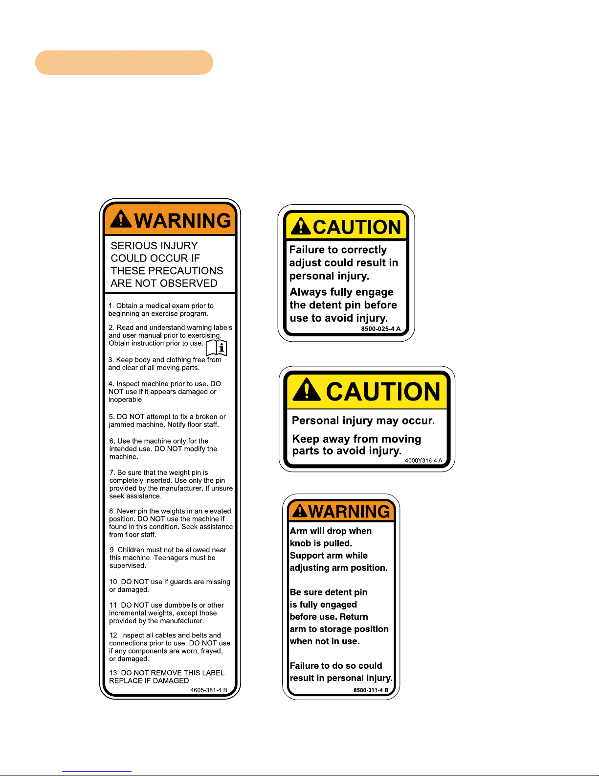
Warnings and Cautions
Warning decals indicate a potentially hazardous situation that could result in death or serious injury if
the precautions are not observed.
Caution decals indicate a potentially hazardous situation, which, if not avoided, could result in minor
or moderate injury.
The diagram following the decals show where each decal is located.
CAUTION
Personal injury may occur.
Keep away from moving
parts to avoid injury.
4000Y316-4 A
7
Page 8
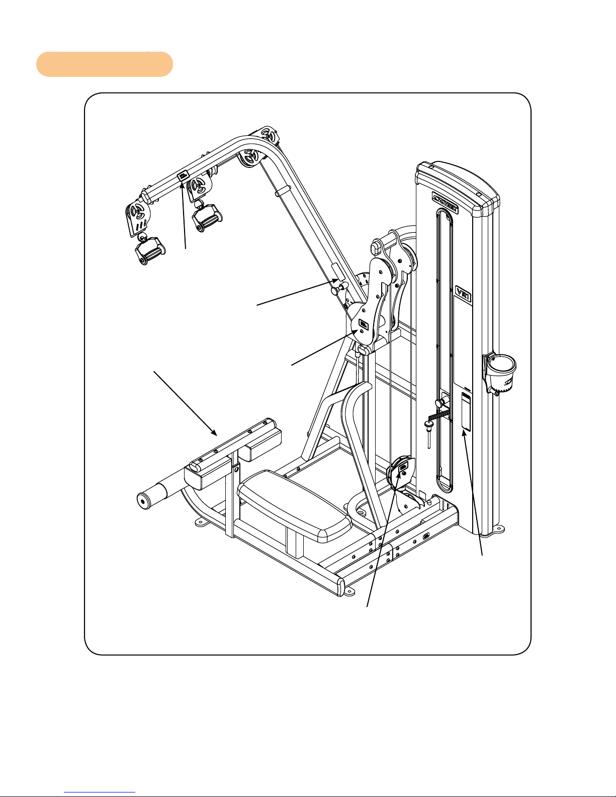
Label Placement
Cybex Owner’s Manual
4000Y316-X
8500-311-X
8500-025-X
4000Y316-X
4605-381-X
4000Y316-X
8
Page 9
Cybex Owner’s Manual
Assembly
Machine Specifications
Total Weight and Size VR1 Lat/Row 13250 Standard Stack
Weight Machine Dimensions at Rest Machine Dimensions in Use
496 Lbs 73” L x 50” W x 77” H Same
225 Kg 185 cm L x 127 cm W x 211 cm H Same
Total Weight and Size VR1 Lat/Row 13250 Standard Stack
Weight Machine Dimensions at Rest Machine Dimensions in Use
426 Lbs 73” L x 50” W x 77” H Same
194 Kg 185 cm L x 127 cm W x 211 cm H Same
Tools Required
• 7/32” Allen wrench
• 3/4” Socket or wrench
• Hammer
• 3/16” Pin punch
Two people will be required for this procedure. It is the responsibility of the facility owner/owner of the
equipment to ensure that there is appropriate clearance around each machine to allow for safe use
and passage.
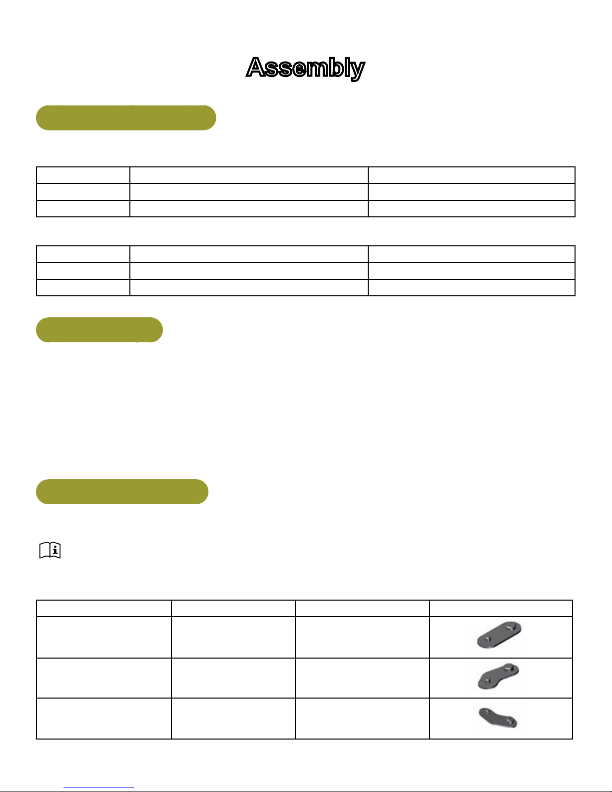
Assembly Procedures
Two people will be required for this procedure.
Read and understand all instructions thoroughly before assembling this unit. Check all items
carefully. If there is damage, see the Customer Service section of this manual for proper procedure to
return, replace, or reorder parts.
Qty Part Number Description Diagram
5 13000-353 Foot Pad
1 13000-354 Foot Pad
1 13000-355 Foot Pad
9
Page 10

Cybex Owner’s Manual
WEIGHT PLATE DETAIL
LIGHT STACK 13000-032
STANDARD STACK
WEIGHT PLATE DETAIL
STANDARD STACK
1
1
1
14
1
14
4800-557
13000-552
4700-337
13000-032
4700-338
13000-036
Move to desired location
If Then
If machine can be
moved without
adding or removing
weight stacks.
Decal, Weight Plate (10-150) (Light)
Decal, Weight Plate (10-220) (Standard)
Weight Stack Plate (Light)
Weight Plate Pack (Light)
Weight Stack Plate (Standard)
Weight Plate Pack (Standard)
Two people will be required for this procedure
1. Move to desired location.
2. Remove the four shipping cones using a 3/4” socket or wrench.
3. Attach foot pads to each foot of frame.
If machine needs
weight stacks
removed before
moving to desired
If Then
Two people will be required for this procedure
1. Remove the two Button Head Socket Cap Screws (BHSCS)
securing the top cap to the frame using a 7/32” Allen wrench.
BHSCS
location.
Top Cap
2. Remove top cap and BHSCS.
3. Lift shroud up and out of machine.
Shroud
10
Page 11

Cybex Owner’s Manual
If Then
4. Remove guide rod caps. Guide rod cap contains a compression
spring that will y if grasp is not released slowly. Slide spring loaded
guide rod cap down guide rod until cap is clear of frame. Slowly
release grasp of guide rod cap and remove.
If machine needs
weight stacks
removed before
moving to desired
location.
Guide
Rod Cap
Compression
Spring
Guide
Rods
Compression
Guide
Rod Cap
Spring
5. Remove guide rod cap and springs.
6. Repeat procedure for opposite guide rods.
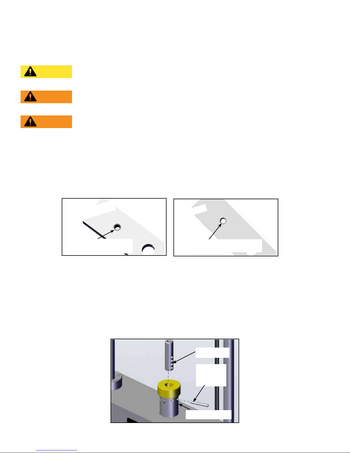
7. Remove spiral pin securing cable end to top weight using a 3/16”
pin punch and hammer.
Cable End
Spiral
Pin
8. Remove lifting post.
9. Remove weight plates
10. Move machine to desired position.
11. Remove the four shipping cones using a 3/4” socket or wrench.
12. Attach foot pads to each foot of frame.
Top Weight
11
Page 12
Cybex Owner’s Manual
Securelyanchormachinetotheoor
Cybex strongly recommends to maximize stability, equipment must be secured to a solid level
surface.
CAUTION: Cybex is not responsible for the actual anchoring of equipment. Consult with
a professional contractor.
WARNING: Use fasteners having a minimum of 500 lbs. tensile capacity (3/8’’ grade 2
bolts or better).
WARNING: If legs/frame does not contact surface, DO NOT pull down with anchors. Shim
any leg or frame not in contact with surface using at washers.
Install weight plates
1. Install individual weight plates one at at time.
2. Position each weight plate so wide edges of bushings face upward and narrow edges
of bushings face downward.
CORRECT
Wide bushing
edge faces upward
WRONG
The narrow bushing edge
must face downward.
3. Install lifting post.
4. Snap guide rods into position.
Cable routing
1. Verify cable is routed through top of pulley bracket and then route cable end to top weight
connector.
2. Pull cable tight and secure in place with spiral pin using a 3/16” pin punch and a hammer.
Cable End
Spiral
Pin
Top Weight
12
Page 13

Cybex Owner’s Manual
3. Place weight stack pin in each plate to verify proper installation.
4. Lift top weight up and down simulating normal operation (without selecting any resistance).
5. Verify that the cable is moving smoothly and is routed straight from the pulley bracket to the
top of the weight plate connector.
Install back shroud
1. Place shroud into position.
2. Secure top in place using two BHSCS and 7/32” Allen wrench.
Verify proper operation
Environment and Storage
Static Electricity
To reduce static electricity increase the humidity.
Humidity
The unit is designed to function normally in an environment with a relative humidity range of 30% to
75%. The unit can be shipped and stored in an environment with a relative humidity range of 10% to
90%.
Temperature
The unit is designed to function normally in an environment with an ambient temperature range of
50° F (10° C) to 104° F (40° C). The unit can be shipped and stored in an environment with a relative
humidity range of 10% to 90%.
Do not install, use, or store the unit in an area of high humidity, such as near a steam room, sauna,
indoor pool or outdoors. Extensive exposure to water vapor, chlorine and/or bromine could adversely
affect the equipment.
13
Page 14
Cybex Owner’s Manual
Exercise
Intended Use
The intended commercial use of this machine is to aid exercise and improve general physical tness.
Instructions
Read and understand all instructions and warnings prior to using this machine in the Safety
section of the Owner’s Manual.
All adjustment points on the machine have yellow handles or knobs.
Lat Pull -
1. Adjust arm assembly to the vertical position.
2. Adjust thigh pad for stabilization during exercise.
3. Grasp handles and sit with with thighs under pad.
Row -
1. Adjust arm assembly to the horizontal position.
2. Grasp handles and sit with thighs under pad and feet on foot rest.
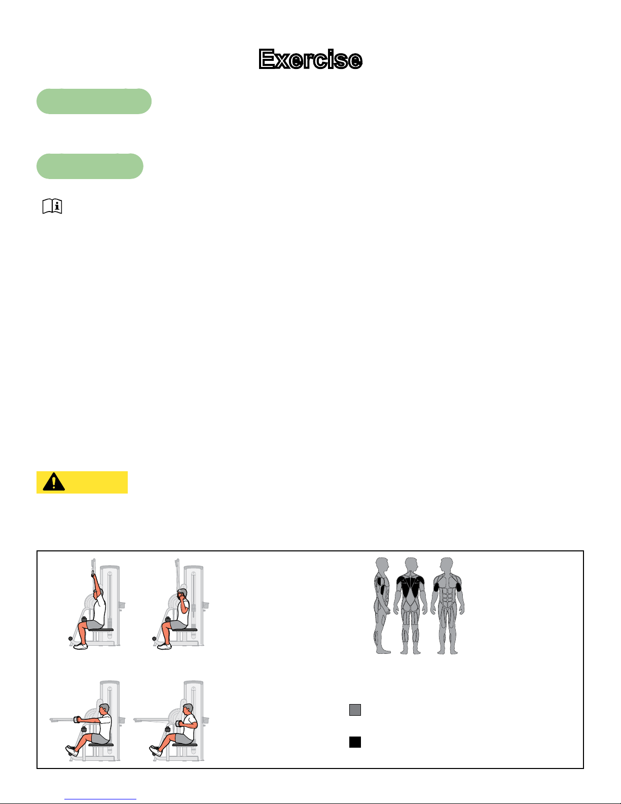
Lat Pull -
1. Pull handles down until elbows are by sides and hands are approximately level with shoulders.
2. Row - Pull handles back to chest.
CAUTION: Serious injury can result if precautions are not followed. Use equipment
only as described in placards located on each machine. Failure to use in the
manner depicted can result in injury.
LAT/ROW
START/FINISH
LAT PULL
START/FINISH
ROW
14
Motions Developed
Shoulder Flexion, Elbow Extension
Muscles Used
Latissimus Dorsi, Teres Major, Biceps,
Lower Trapezius, Middle Trapezius,
Rear Deltoid, Rhomboid
Page 15

Cybex Owner’s Manual
NOTE: All inspections
and repairs must be
performed by trained
service personnel only.
Maintenance
All preventive maintenance activities must be performed on a regular basis. Performing routine
preventive maintenance actions can aid in providing safe, trouble-free operation of all Cybex Strength
Systems equipment.
Cybex is not responsible for performing regular inspection and maintenance actions for your
machines. Instruct all personnel in equipment inspection and maintenance actions and also in
accident reporting/recording. Cybex representatives are available to answer any questions that you
may have.
All inspections and repairs must be performed by trained service personnel only. Cybex will
void warranty if non-Cybex replacement parts are used.
CAUTION
Use only Cybex replacement
parts when servicing.
Failure to do so could result
in personal injury.
Daily Procedures
When using strong cleaning agents such as rubbing alcohol or bleach, it is advisable to rst test in an
inconspicuous area. Other cleaning agents may contain harsh or unknown solvents and are subject to
formula changes by the product manufacturer without notice. Should you desire to use other cleaning
agents, carefully try them in an inconspicuous area to determine potential damage to the material.
Never use harsh solvents or cleaners which are intended for industrial applications. To clean stained
or soiled areas, a soft white cloth is recommended. Avoid use of paper towels.
Cleaning products may be harmful/irritating to your skin, eyes, etc. Use protective gloves and eye
protection. Do Not inhale or swallow any cleaning product. Protect surrounding area/clothing from
exposure. Use in well ventilated area. Follow all product manufacturer’s warnings. CYBEX and
its vendors cannot be held responsible for damage or injuries resulting from the use or misuse of
cleaning products.
15
Page 16

Clean Upholstery
Cybex Owner’s Manual
If Then
1. Prepare a solution of 10% household
liquid soap and warm water.
2. Apply with a soft damp cloth.
Light Soiling
MoreDifcultStains
3. If necessary, apply a solution of liquid
cleanser with a soft bristle brush.
4. Dampen a clean soft cloth in water and
wipe residue away.
1. Prepare a solution of 10% household
bleach (sodium hypochlorite) and 90%
water. Dampen a soft white cloth in the
solution.
2. Rub gently on the stained area.
3. Dampen a clean soft cloth in water and
rinse area.
4. If stains are still present, a full strength
household bleach may be used. Allow
bleach to puddle on the affected area
or apply with a bleached-soaked cloth
for approximately 30 minutes. Dampen
a clean soft cloth in water, and rinse
area to remove any remaining bleach
concentration.
1. Dampen a soft white cloth with rubbing
alcohol.
MoreDifcultStains(AlternativeMethod)
Restoring Luster
Clean Frames
Wipe down all frames using a mild solution of warm water and car wash soap. Be sure to dry
thoroughly. AVOID acid or chlorine based cleaners and also cleaners containing abrasives as these
could scratch or damage the equipment.
2. Gently rub stained area.
3. Dampen a clean soft cloth in water and
rinse area.
1. Apply a light coat of furniture wax for 30
seconds.
2. Lightly rub area using a clean white cloth.
16
Page 17

Cybex Owner’s Manual
Clean Chrome
Clean chrome tubes, rst using chrome polish and then using a car wax seal. Neutral cleaners with a
pH between 5.5 and 8.5 are recommended. Be sure to dry thoroughly. AVOID acid or chlorine based
cleaners and also cleaners containing abrasives as these could scratch or damage the equipment.
Guidelines for cleaning front panel:
Use clean soft cloths or sponges for application of cleaners and again for washing and rinsing. Follow
up each application with warm water rinse.
• DO NOT use abrasives or high alkaline cleaners.
• DO NOT leave cleaners on for long periods, wash immediately.
• DO NOT apply cleaners in direct sunlight or at elevated temperatures.
• DO NOT use scrapers, squeegees, or razors.
• DO NOT clean with gasoline.
Compatible Cleaners and Detergents:
• Formula 409
• Top Job
• Joy
• Palmolive
• Windex with Ammonia D
To Minimize Fine or Hairline Scratches:
Mild automotive polish applied and removed with a soft clean cloth will help ll scratches.
Suggested Polishes:
• Johnson Paste Wax
• Mirror Glaze #10 Plastic Polish (by Mirror Bright Polish Co.)
• Novus Plastics Polish #1, #2 (By Novus Inc.)
17
Page 18

Cybex Owner’s Manual
Weekly Procedures
Inspect All Nuts and Bolts
Tighten all loose nuts and bolts as required.
WARNING: Serious injury or death may result if the following precautions are not
followed. Replace all worn cables and belts. Worn cables and belts can fail if
not replaced.
Inspect cables and belts
Inspect all cables and belts for wear or damage and proper tension. When inspecting cables and
belts, run ngers on the cable or belt, paying particular attention to bends in cables and attachment
points. The following conditions may indicate a worn cable:
Cables
Condition of Cable Diagram
A tear or crack in the cable sheath
that exposes the cable
A kink in the cable
A curled sheath
Necking - A stretched cable sheath
18
Page 19

Belts
Cybex Owner’s Manual
Condition of Belt 3D View 3D or Side View
Peeling of the belt’s skin.
Wave in belt
Belt is necked down (narrow section)
Cracks or splits
One or more strands of kevlar is
hanging out, or if there is a signicant
amount of frayed kevlar.
Replace belt if any
section is over 1/32”
(.03) narrower than the
rest of belt
Examine edge of belt (both sides).
Replace belt if any section is
narrower than the rest.
19
Page 20

Cybex Owner’s Manual
CAUTION: Personal injury or property damage may occur if the following precautions
are not followed. Do not use if less than 1/8” of material remains to the edge.
Replace all worn handles immediately. Failure to replace worn handles can
result in injury or property damage.
Inspect bars and handles for wear, paying particular attention to tab area connection points.
Replace bar if less
than 1/8” of material
remains to the edge.
Attachment
Hole
Inspection Action
Inspect bars and handles for wear, paying
particular attention to tab area connection points.
Inspect snap links for proper latching (indicates
wear).
Inspect all labeling for readability, including
instructional placards, warning and caution
decals.
Inspect all weight stacks for proper alignment
and operation.
Inspect guide rods for lubrication.
Yearly Procedures
Replace all cables and belts annually
Replace all worn handles immediately.
Replace all loose or worn grips immediately.
Replace all worn labeling immediately.
Correct all improper alignment and operation
issues immediately.
Wipe Weight Stack Guide Rods clean over entire
length. Lubricate with a light coat of medium
weight automotive engine oil.
20
Page 21

Cybex Owner’s Manual
Cable Adjustment
Tools Required
9/16” Wrench (2)
Four types of cable tension adjustment are used on Cybex Strength Systems:
Cable
Adjustment
Jam Nut
Adjustment
Rod End
Adjustment
Description Diagram
This type of adjustment uses a jam
nut and a tension adjustment nut at
the cable cam end as the primary
adjustment. The other end of the
cable usually contains a roll pin
adjustment.
This type of adjustment uses a
socket head cap screw (SHCS)
securing a cable rod end bearing to
the machine. Primary adjustment
is by turning the rod end bearing.
The other end of the cable usually
contains a roll pin cable adjustment.
Jam
Cable
End
SHCS
Nut
Tension
Adjustment
Nut
Jam Nut
Cable Rod End
Bearing
Nylon
Locknut
Roll Pin
Adjustment
This type of adjustment uses a roll
pin and series of holes in the weight
stack top weight connector.
This type of adjustment uses an
Cam End
Adjustment
adjustment bolt on the pulley
bracket. Loosen nut and rotate cam
bolt to adjust cable.
21
Roll
Pin
Nut
Top Weight
Connector
Cam Bolt
Adjustment
Page 22

Cybex Owner’s Manual
Belt Adjustment
Tools Required
• 7/32” Wrench
• Torque wrench (lbs-in)
Belt Adjustment Action
1. Using a 7/32” Allen wrench loose set screws.
2. Pull belt tight.
Loose Belt
3. Secure belt in place with set screws.
4. Torque set screws to 300-350 lb-in.
5. Verify that the belt is moving smoothly and is routed straight from
the top pulley bracket to the to weight belt clamp
22
Page 23

Cybex Owner’s Manual
Customer Service
Product Registration
To register product do the following:
1. Visit www.cybexintl.com.
2. Locate Product Registration in the Support section.
3. Fill out form completely.
4. Click the Submit button to register product.
Contacting Service
Hours of phone service are Monday through Friday from 8:30 a.m. to 6:00 p.m. Eastern Standard
Time.
For Cybex customers living in the USA, contact Cybex Customer Service at 888-462-9239.
For Cybex customers living outside the USA, contact Cybex Customer Service at 508-533-4300 or
fax 508-533-5183. email address internationaltechhelp@cybexintl.com
Find information on the web at www.cybexintl.com.
To contact us online go to www.cybexintl.com. Select Support > Service. In the left navigation panel,
click Get Service - Service Request Form. Fill out form completely and click the Submit Query button.
23
Page 24

Cybex Owner’s Manual
Ordering Parts
TTo order parts online go to www.cybexintl.com. Select Support > Parts / Ordering. In the left
navigation panel, click Parts Diagrams - Current Products. Select from the drop down boxes.
To speak with a customer service representative, call 888-462-9239 (for customers living within the
USA) or 508-533-4300 (for customers outside the USA).
The following information located on the serial number decal will assist our Cybex representatives in
serving you.
• Unit Serial Number, Product Name and Model Number
• Part Description and Part Number if you have it. All parts can be found on the web at
www.cybexintl.com
• Shipping Address
• Contact Name
• Include a description of the problem.
In addition to your shipping address and contact name, your account number is helpful but not
required. You may also fax orders to 508-533-5183.
Return Material Authoriazation (RMA)
The Return Material Authorization (RMA) system is used when returning material for placement,
repair or credit. The system assures that returned materials are properly handled and analyzed.
Follow the following procedures carefully.
Contact your authorized Cybex dealer on all warranty-related matters. Your local Cybex dealer will
request a RMA from Cybex, if applicable. Under no circumstances will defective parts or equipment
be accepted by Cybex without proper RMA and an Automated Return Service (ARS) label.
Please contact Cybex Customer Service for the return of any item that is defective.
Provide the technician with a detailed description of the problem you are having or the defect in the
item you wish to return. Provide the model and serial number of your Cybex equipment.
At Cybex’s discretion, the technician may request that you return the problem part(s) to Cybex for
evaluation and repair or replacement. The technician will assign you a RMA number and will send
you an ARS label. The ARS label and the RMA numbers must be clearly displayed on the outside
of the package that contains the item(s) to be returned. Include the description of the problem, the
serial number of the equipment and the name and address of the owner in the package along with the
part(s).
Merchandise returned without an RMA number on the outside of the package or shipments sent COD
will not be accepted by the Cybex receiving department.
24
Page 25

Cybex Owner’s Manual
Damaged Parts
Materials damaged in shipment should not be returned for credit. Shipping damages are the
responsibility of the carrier (UPS, Federal Express, trucking companies, etc.)
Apparent Damage
Upon receipt of your shipment, check all items carefully. Any damage seen with a visual check must
be noted on the freight bill and signed by the carrier’s agent. Failure to do so will result in the carriers
refusal to honor your damage claim. The carrier will provide you with the required forms for ling such
claims.
Concealed Damage
Damage not seen with a visual check upon receipt of a shipment but notices later must be reported
to the carrier as soon as possible. Upon discovery of the damage, a written or phone request to
the carrier asking them to perform an inspection of the materials must be made within ten days of
the delivery date. Keep all shipping containers and packing materials as they will be needed in the
inspection process. The carrier will provide you with an inspection report and the necessary forms for
ling a concealed damage claim. Concealed damage claim is the carrier’s responsibility.
25
Page 26

Page 27

Page 28

10 Trotter Drive Medway, MA 02053 • 508-533-4300 • FAX 508-533-5183
www.cybexintl.com
 Loading...