

Page 1

Cybex 525C/525R Cycle
Owner’s Manual
Cardiovascular Systems
Part Number LT-24303-4 D
www.cybexintl.com
Page 2

Cybex Owner’s Manual
Table of Contents
Safety
Grounding and Voltage Information ........4
Important Safety Instructions ............. 5
Warning and Caution Decals ............. 6
Warning and Caution Decals - 525C ....... 7
Warning and Caution Decals - 525R ....... 9
Assembly
Specications ........................ 11
Choosing and Preparing a Site........... 12
Electrical Power Requirements .......... 13
Unit Assemby ........................ 13
525C Assembly....................... 14
525R Assembly....................... 20
Setup .............................. 27
A/V Cong and FM Radio Presets . . . . . . . . 29
E3 View Monitor Controls............... 34
E3 View Monitor Setup................. 35
Testing the Operation .................. 44
Operation
Intended Use ........................ 45
Terms Used ......................... 45
User Control Symbols Used ............. 46
Console Display . . . . . . . . . . . . . . . . . . . . . . 47
User Controls . . . . . . . . . . . . . . . . . . . . . . . . 48
Mount and Dismount .................. 48
Emergency Dismount .................. 49
Quick Operation Guide................. 49
Detailed Operation Guide............... 49
Workout Selection .................... 51
Data Readouts . . . . . . . . . . . . . . . . . . . . . . . 52
Heart Rate Indicator ................... 52
E3 View Monitor Monitor Screen Options... 53
iPod/iPhone/iPad Functions ............. 53
Battery Sentry........................ 53
Maintenance
Warnings ...........................54
Preventive Maintenance Activities ........55
Cleaning Unit ........................ 55
Rechargeable Battery.................. 56
E3 View Monitor ...................... 56
Environment ......................... 57
Customer Service
Product Registration................... 58
Contacting Service .................... 58
Ordering Parts ....................... 58
Return Material Authorization (RMA) ......59
Damaged Parts....................... 59
Appendix - Workout Overviews
1 - Weight Loss....................... 60
2 - Rolling Hills . . . . . . . . . . . . . . . . . . . . . . . 61
3 - Hills ............................. 62
4 - Pike’s Peak ....................... 63
5 - Ramps........................... 64
6 - Interval........................... 65
7 - Strength.......................... 66
8 - Cardio ........................... 67
9 - Heartrate Control (E3 View
Monitor Option) .................... 68
Cybex® and the Cybex logo are registered trademarks of Cybex International, Inc. Polar® is a registered trademark of Polar Electro Inc. iPod, iPhone,
and iPad are trademarks of Apple Inc., registered in the U.S. and other countries.
DISCLAIMER: Cybex International, Inc., makes no representations or warranties regarding the contents of this manual. We reserve the right to revise
this document at any time or to make changes to the product described within it without notice or obligation to notify any person of such revisions or
changes.
© 2014, Cybex International, Inc. All rights reserved. Printed in the United States of America.
10 Trotter Drive Medway, MA 02053 • 508-533-4300 • FAX 508-533-5183 • www.cybexintl.com • LT-24303-4 D • January 2014
2
Page 3

Cybex Owner’s Manual
FCC Compliance Information
Changes or modications to this unit not expressly approved by the party responsible for compliance
could void the user’s authority to operate the equipment!
This equipment has been tested and found to comply with the limits for a Class B digital device,
pursuant to part 15 of the FCC Rules. These limits are designed to provide reasonable protection
against harmful interference in a residential installation. This equipment generates, uses and can
radiate radio frequency energy and, if not installed and used in accordance with the instructions,
may cause harmful interference to radio communications. However, there is no guarantee
that interference will not occur in a particular installation. If this equipment does cause harmful
interference to radio or television reception, which can be determined by turning the equipment off
and on, the user is encouraged to try to correct the interference by one or more of the following
measures:
• Reorient or relocate the receiving antenna.
• Increase the separation between the equipment and receiver.
• Connect the equipment into an outlet on a circuit different from that to which the receiver is
connected.
• Consult the dealer or an experienced radio/TV technician for help.
3
Page 4
Cybex Owner’s Manual
Safety
Read all instructions and warnings before using.
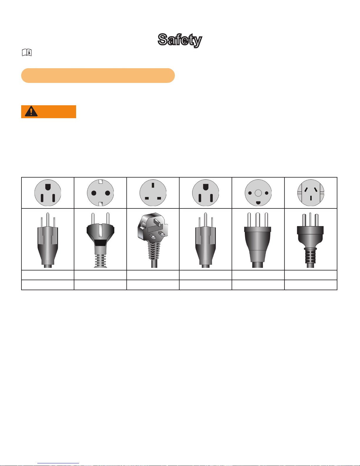
Grounding and Voltage Information
AC Power Adapter is optional.
WARNING: Shock and electrocution hazard
• Connect unit to a grounded outlet.
• Do not use voltage adapter or extension cord.
Cybexisnotresponsibleforinjuriesordamagesasaresultofcordorplugmodication.
• Verify voltage requirements of unit match local voltage requirements.
• Verify unit outlet is the same conguration as the plug.
115 VAC Euro Plug UK 230 VAC Japanese Danish Australia
NEMA 5-15 CEE 7/7 BS 1363 JIS 8303 107-2-D1 AS/NZS 3112
4
Page 5

Cybex Owner’s Manual
Important Safety Instructions
(Save These Instructions)
WARNING: Shock and electrocution hazard
• Unplug unit and let sit 10 minutes before cleaning or performing maintenance
• Electrical charge can remain in unit after unplugging
• Keep water and liquids away from electrical parts
User Safety Precautions
Prior to use:
• Obtain a medical exam before beginning any exercise program.
• Obtain instruction before using.
Read and understand warning labels.
•
• Maximum user weight is 400 lbs. (180 kg).
• Inspect unit. If damaged, notify oor staff. DO NOT USE.
• Do not remove this label. Replace if damaged or illegible.
During use:
• Do not use for stretching and do not attach straps or other devices.
• Do not allow children 12 or younger to be on or near machine.
• Stop exercise if feeling faint, dizzy, or have pain.
• Use the handrails for support and to maintain balance.
• Keep all body parts, clothing, and accessories, clear of moving parts.
Facility Safety Precautions
It is the sole responsibility of the user/owner or facility operator to ensure that regular maintenance is
performed.
• Enforce all user and safety precautions.
• Read and understand the Owner’s Manual completely before assembling, servicing or using unit.
• Verify all users are properly trained on using the equipment.
• Do not use unit outdoors.
• Verify that each unit is setup, leveled and operated on a solid, level surface. Do not install
equipment on an uneven surface.
• Verify there is enough room for safe access and operation of unit.
• Use Cybex AC power adapters only.
• Do not use the optional power adapter in damp or wet locations.
• Do not use the unit if: (1) the unit is plugged into an optional power adapter that has a damaged
cord; (2) the unit is not working properly or (3) if the unit has been dropped or damaged. Seek
service from a qualied technician.
• EQUIPMENT is not suitable for use in the presence of aerosol (spray), FLAMMABLE
ANAESTHETIC MIXTURE WITH AIR or WITH OXYGEN or NITROUS OXIDE.
• Perform regular maintenance checks on unit. Performance level can be maintained only if
examined regularly. Pay close attention to all areas most susceptible to wear, including (but not
limited to) cables, pulleys, belts and grips.
• Replace any warning labels if damaged, worn or illegible.
• Immediately replace worn or damaged components. If unable to immediately replace worn or
Page 6

Cybex Owner’s Manual
damaged components, then remove unit from service until repair is made.
• Do not attempt repairs; electrical or mechanical. Seek qualied repair technician when servicing.
Failure to do so could result in serious injury. See Customer Service for contact information.
• Use only Cybex supplied components to maintain/repair unit.
• Keep a repair log of all maintenance activities.
• Disconnect the optional power adapter before servicing unit.
• Do not use attachments unless recommended for the unit by Cybex.
• The unit may generate electromagnetic or other forms of interference, or it may be affected by
interference from other equipment nearby. If this is suspected, take precautions by separating the
equipment or otherwise shielding it to avoid such interference.
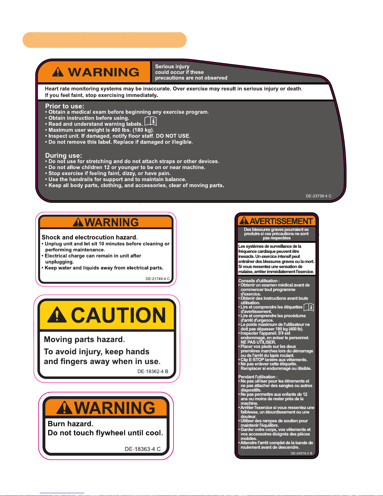
Warning and Caution Decals
To replace any worn or damaged decals do one of the following: Visit www.cybexintl.com to shop
for parts online, fax orders to 508-533-5183 or contact Cybex Customer Service at 888-462-9239. If
you are located outside of the USA, call 508-533-4300. For location or part number of labels, see the
parts list and exploded-view diagram on the Cybex web site at www.cybexintl.com.
Warning decals indicate a potentially hazardous situation which, if not avoided, could result in death
or serious injury.
Carefully read and understand the following caution and warning labels before using the unit.
6
Page 7
Cybex Owner’s Manual
SEE SHEET 1
ECOREV
6.433”W X 2.950”H
REVISIONS
DESCRIPTION
See sheet 1
ECO
REV
BY
.
.
3.125”W X 1.65”H X 0.19”R
BLACK
WHITE
ORANGE PMS 152C
REVISIONS
DESCRIPTION
SEE SHEET 1
ECOREV
2.5”W X 1.5”H X 0.19”R
BLACK
WHITE
YELLOW PMS 108C
REVISIONS
DESCRIPTION
SEE SHEET 1
ECOREV
DATE APPROVALBY
Black
White
Orange - Pantone 152C
Gray- Pantone 425C
2.0”W X 6.0”H
DIELINE “CutContour” DO NOT PRINT
Warning and Caution Decals - 525C
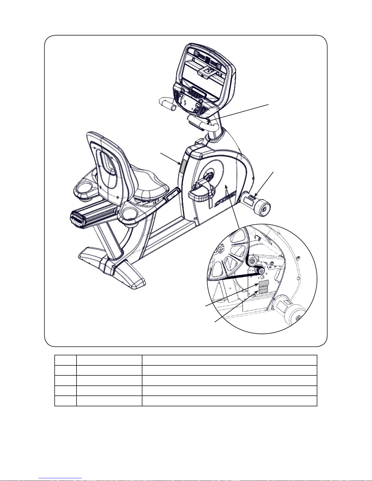
Page 8

Cybex Owner’s Manual
1
5
2
3
4
1 DE-23739-4 Label, Warning, Access tray,
2 DE-21749-4 Label, Warning, Disconnect Power
3 DE-18363-4 Label, Warning, Hot ywheel
4 DE-18362-4 Decal, Caution moving parts
5 DE-24016-2 Label, Warning, Canada
8
Page 9
Cybex Owner’s Manual
REVISIONS
DESCRIPTION
SEE SHEET 1
ECOREV
4.70”W X 3.03”H
REVISIONS
DESCRIPTION
See sheet 1
ECO
REV
BY
.
.
3.125”W X 1.65”H X 0.19”R
BLACK
WHITE
ORANGE PMS 152C
REVISIONS
DESCRIPTION
SEE SHEET 1
ECOREV
2.5”W X 1.5”H X 0.19”R
BLACK
WHITE
YELLOW PMS 108C
REVISIONS
DESCRIPTION
SEE SHEET 1
ECOREV
DATE APPROVALBY
Black
White
Orange - Pantone 152C
Gray- Pantone 425C
2.0”W X 6.0”H
DIELINE “CutContour” DO NOT PRINT
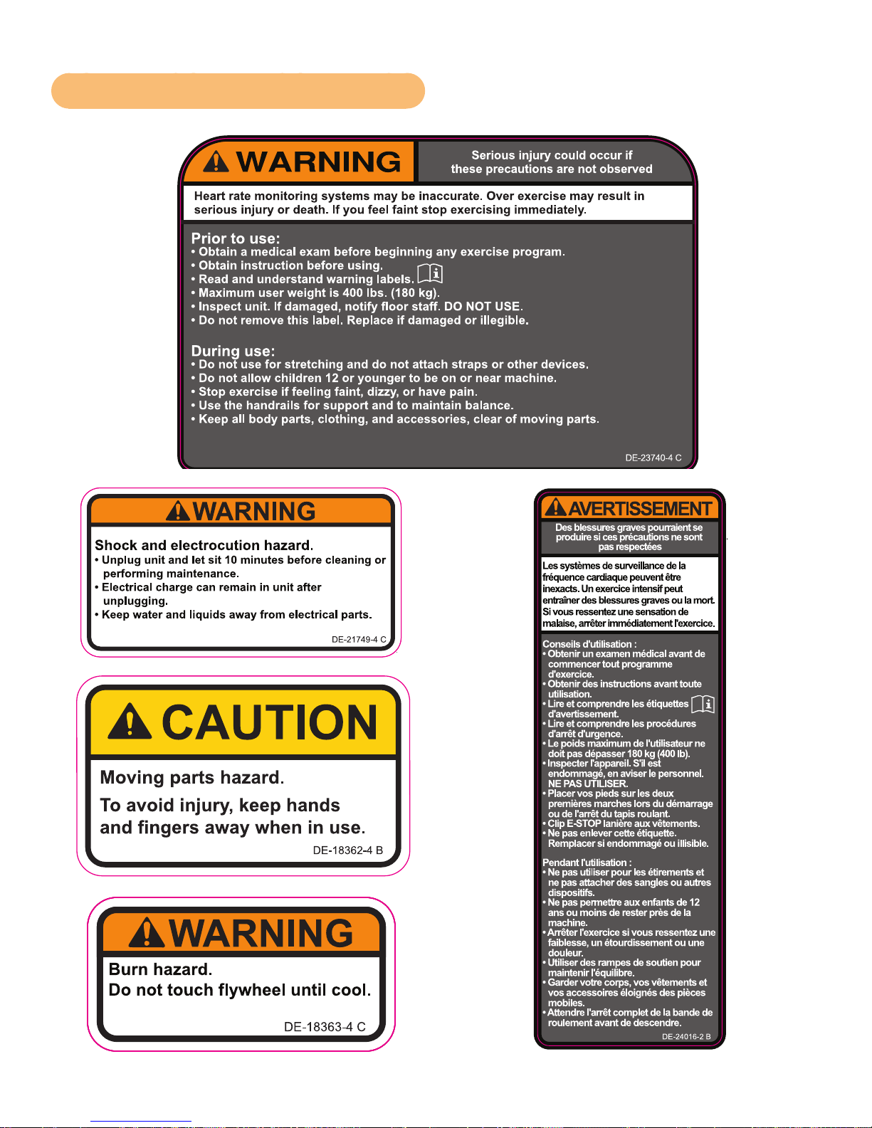
Warning and Caution Decals - 525R
Page 10
Cybex Owner’s Manual
5
1
2
1 DE-23740-4 Label, Warning, Access tray,
2 DE-21749-4 Label, Warning, Disconnect Power
3 DE-18363-4 Label, Warning, Hot ywheel
4 DE-18362-4 Decal, Caution moving parts
5 DE-24016-2 Label, Warning, Canada
3
4
10
Page 11
Cybex Owner’s Manual
Assembly
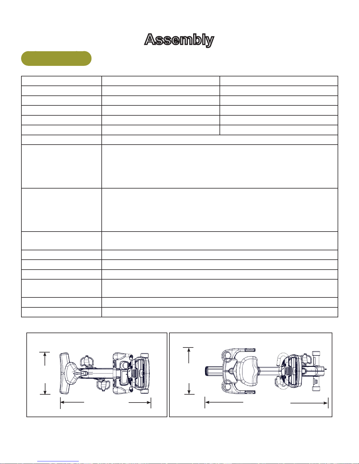
Specifications
525C Cycle 525R Cycle
Length: 48” (122 cm) 65” (165 cm)
Width: 23” (58 cm) 24” (62 cm)
Height: 61” (155 cm) 49” (125 cm)
Weight of Product: 143 lbs. (65 kg) 166 lbs. (75 kg)
Shipping Weight 173 lbs. (78 kg) 196 lbs. (89 kg)
Resistance Levels: 21 (User selected in Manual or Bike Mode)
Workouts: Quick Start, eight workouts, and Heart Rate Control for E3 View Monitor
option.
Quick Start is facility selectable as “Bike” mode or Constant Power.
Weight Loss and Cardio workouts are constant power.
Quick Start and Workouts have 21 levels.
Console Features: Upper console: LED or E3 View Monitor.
Displays - Time, BPM, Weight, Calories, RPM, and Cal/Hr.
E3 View Monitor also displays Watts, MET, and Distance.
Lower console: Left numeric display for gear or level.
Right numeric display for road speed, watts, or target RPM.
Heart Rate Features: Built-in wireless heart rate receiver (transmitter not included) and contact
heart rate monitoring.
Resistance Range: Minimum - 20 Watts; Maximum - 900 Watts.
Maximum User Weight: 400 lbs. (181 kg).
Power: Self-powered or optional AC adapter for full time display.
Power Supply: 100-240 V, 50/60 Hz, 1.0 A, AC (9V DC, 1.7A). NEMA 5-15 plug
(TR-18231) or IEC-320 inlet (TR-18230).
Other: Water bottle holder and utility tray.
Options: E3 View Monitor, Wireless audio receiver, iPod/iPhone/iPad compatibility.
525C Cycle
23”
(58 cm)
48” (122 cm)
525R Cycle
24”
(62 cm)
65” (165 cm)
11
Page 12
Cybex Owner’s Manual
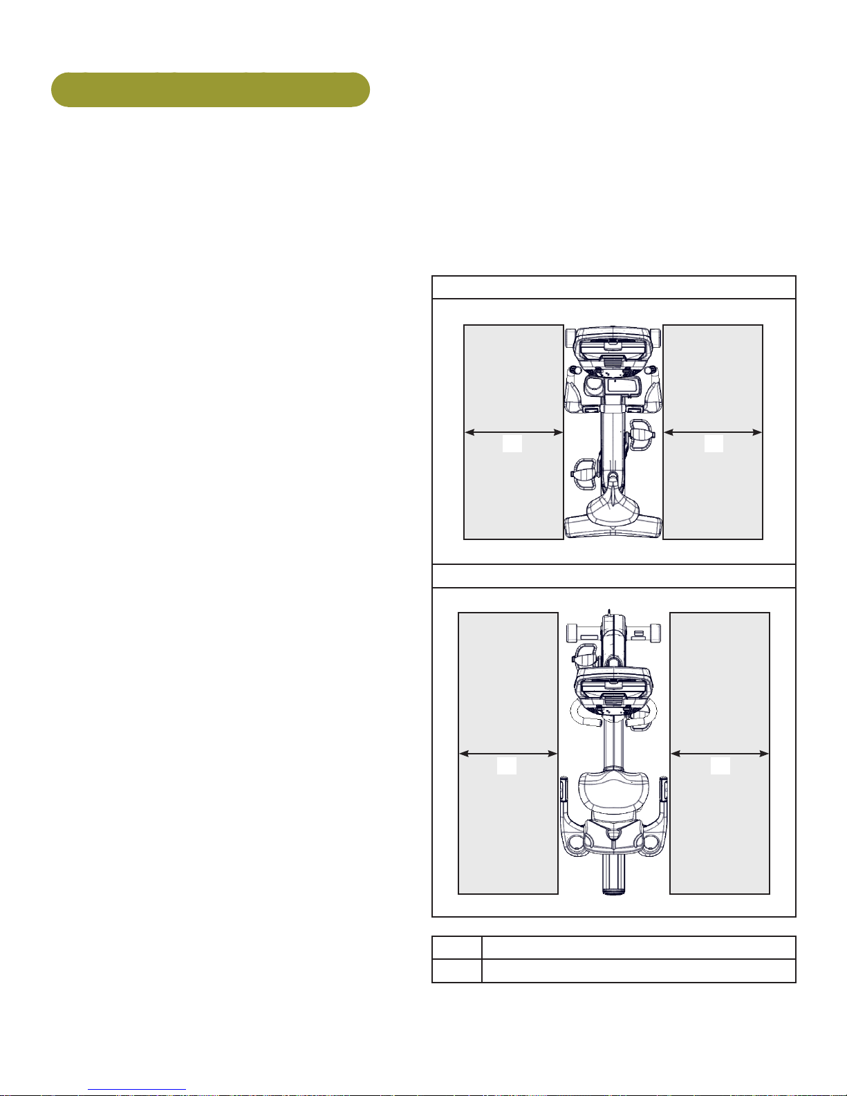
Choosing and Preparing a Site
Before assembling the unit, verify the chosen site meets the following criteria:
• Area is well lit and well ventilated.
• Surface is structurally sound and properly leveled.
• Free area for access to unit and emergency dismount. Minimum clearance is 23.6 inches (0.6
meters).
• Adjacent units may share the free area.
It is the responsibility of the facility owner/
owner of the equipment to ensure that there is
appropriate clearance around each machine to
allow for safe use and passage.
In compliance with the ADA (American
Disabilities Act) there must be clear oor space
of at least 30 by 48 inches and be served by an
accessible route for at least one of each type
of exercise equipment. If the clear space is
enclosed on three sides (e.g., by walls or the
equipment itself), the clear space must be 36 by
48 inches.
All other machines must have a clear oor space
of 23” for all access point on the machine.
The dimensions stated in the assembly
instructions of this manual include the maximum
foot print (in use) dimensions.
• Area is not in the vicinity of high humidity,
such as in the vicinity of a steam room, sauna,
indoor pool or outdoors. This unit is designed
to function normally in an environment with a
relative humidity range of 30% to 75%.
Exposure to extensive water vapor, chlorine and/
or bromine could adversely affect the electronics
as well as other parts of the unit.
525C
1 1
525R
1 1
• Area maintains an ambient temperature range
of 50° F (10° C) to 104° F (40° C) degrees.
Free area
1 23.6”, 0.6m
12
Page 13

Cybex Owner’s Manual
Electrical Power Requirements
The AC power kit is optional.
Verify the unit is connected to an outlet having the same conguration as the plug.
Verify connection is a grounded circuit. Do not use a ground-plug adapter to adapt the 3-prong power
cord to a non-grounded electrical outlet.
Use Cybex supplied AC power kit only. Consult an electrician with any questions.
Verify power supply is compliant with local building codes.
Unit Assemby
Tools Required
• 3/16” Allen wrench (supplied with 525R only)
• Phillips screwdriver
• 1/2” Socket wrench
• 9/16” Open end wrench
The words “left” and “right” denote the user’s orientation.
Read and understand all instructions thoroughly before assembling the unit.
Verifycorrectpackage.
1. Read box label to verify the model number and voltage match what was ordered.
2. Lift and remove cardboard sleeve surrounding unit.
3. Verify paint color matches what was ordered.
4. Verify correct voltage by reading voltage sticker near power outlet. AC power kit is optional.
13
Page 14
Cybex Owner’s Manual
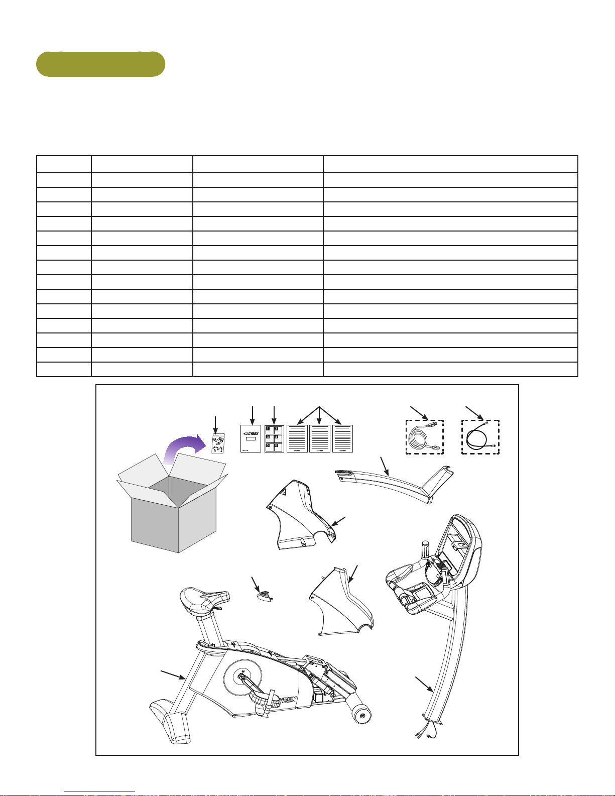
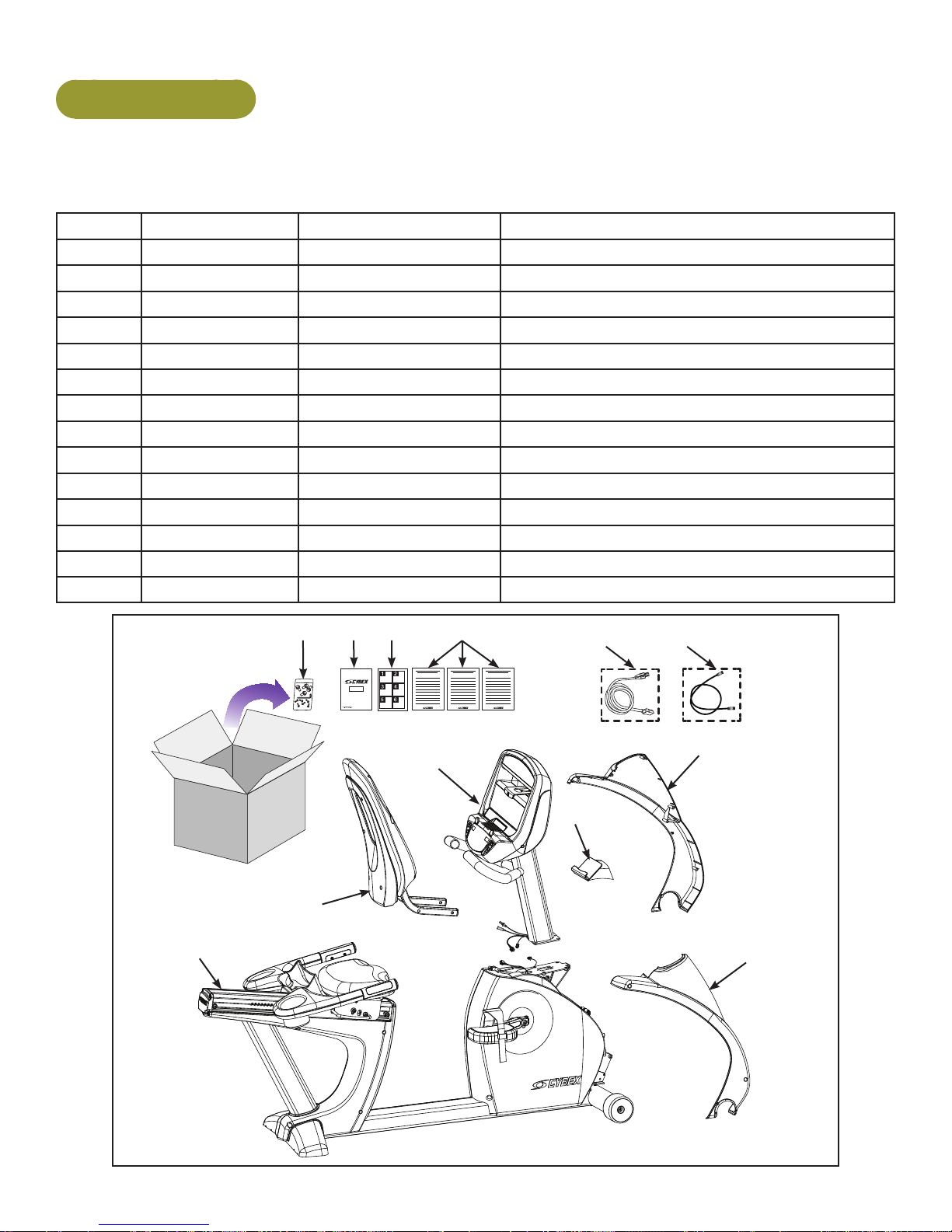
525C Assembly
Unpackandverifycontentsofboxes.
Verify the following items are present. See Customer Service chapter for contact information if any
parts are missing.
Item Quantity Part Number Description
1 1 Varies Base with covers attached
2 1 Varies Console assembly
3 1 PL-21584 Back Cap
4 1 PL-21581 Front Left Cover
5 1 PL-21582 Front Right Cover
6 1 PL-21583 Top Cap
7 1 AX-21698 Hardware pack
8 1 LT-24303-4 Owner’s Manual
9 1 LT-24300 Assembly poster
10 1 LT-24291 Warranty sheet, Consumer
10 1 LT-24292 Warranty sheet, Commercial, Entry
10 1 LT-24293 Warranty sheet, Commercial, Full
11 1 Varies Power cord (E3 View Monitor option)
12 1 AW-23836 Cable, 6’, Coax (E3 View Monitor option)
879 10
11 12
6
4
5
3
1
2
14
Page 15
Cybex Owner’s Manual
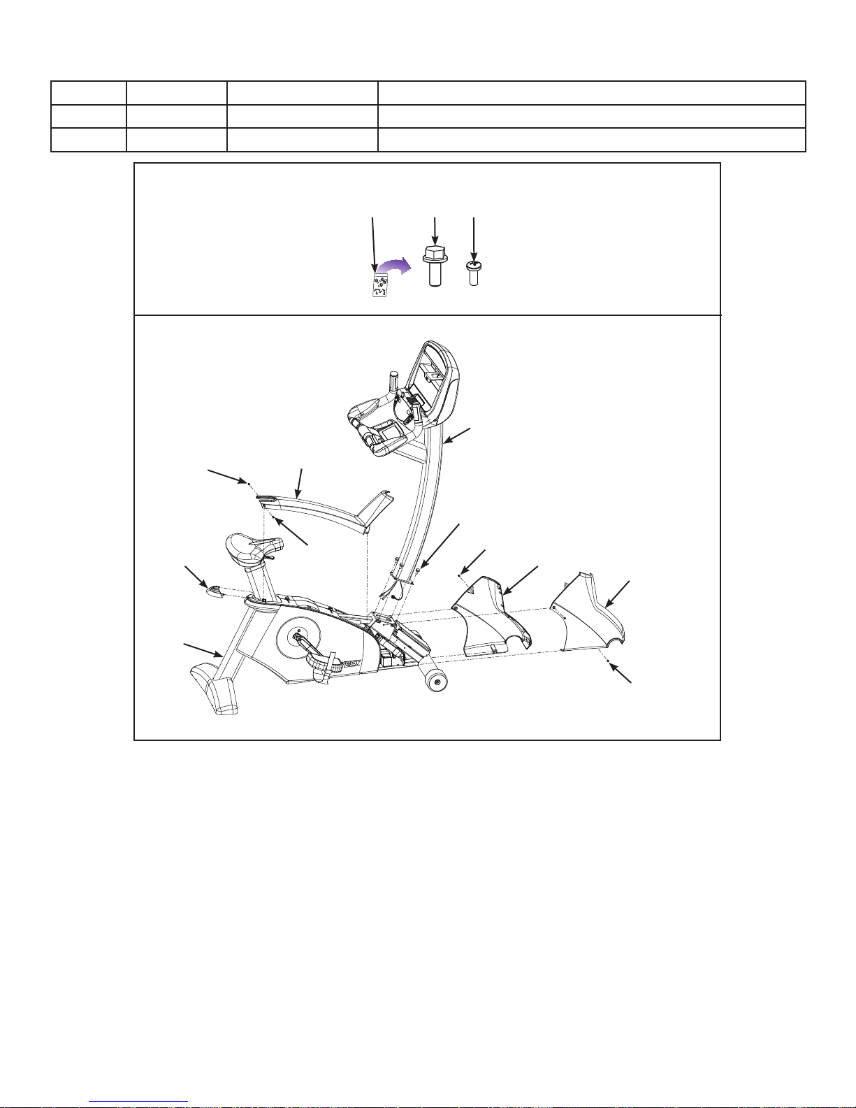
Item Quantity Part Number Description
13 4 HS-19108 Screw, 5/16-18 x .75”,HXHD,WHIZ-LOCK,GR5
14 6 HS-15706 Screw, 8-16 x .50”, PNHD
Hardware
137
14
2
14
6
13
3
14
14
4
5
1
14
Lift and move the unit
1. Grasp the rear foot.
2. Lift the rear foot so the front transport wheels are able to roll on oor. Use proper lifting
methods.
3. Roll unit to intended location.
4. Lower the rear foot so unit is in intended location.
15
Page 16
Cybex Owner’s Manual
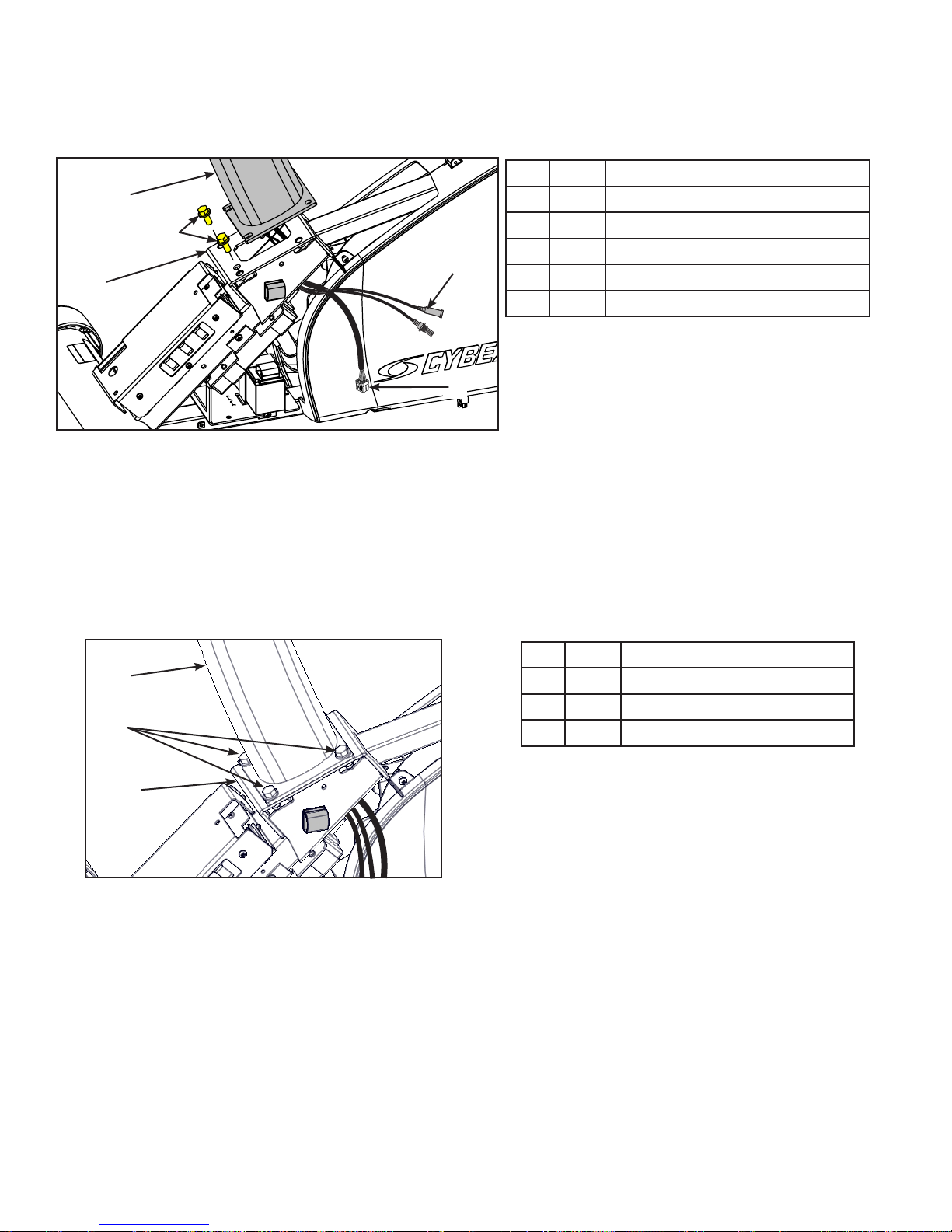
Installconsoleassemblytobaseassembly.
1. Hand thread two mounting screws into the base assembly.
Item Description
1
2
1 Console assembly
2 13 Screws (2)
3 Base assembly
4
3
4 Optional A/V cable
5 Display cable
5
The console assembly will need to be supported during steps 2 through 5.
2. Insert the display cable and optional A/V cable through the frame to the left side. Do not pinch
or damage the cables during assembly.
3. Place the console assembly in the correct position on the base assembly by sliding into
position onto the two mounting screws.
4. Hand thread the other two screws.
Item Description
1
1 Console assembly
2 13 Screws (4)
2
3 Base assembly
3
5. Securely fasten the four screws with a 1/2” socket wrench.
16
Page 17
Cybex Owner’s Manual
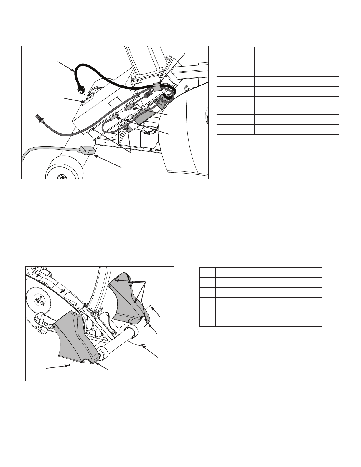
6. Route cables through gray clip on controller.
3
1
Item Description
1 Display cable
2 Display cable connector
3 Gray clip
2
4 Power supply output
5 Console cable DIN
connector
4
6 A/V cables, optional
7 11 Power cord
5
6
7
7. Plug the display cable into the display cable connector on the lower control board. Ensure the
cable connector is securely fastened.
8. Connect the console cable’s DIN connector to the power supply output. Make sure the two
connectors snap rmly together and can not be pulled apart without pulling the sleeve back to
release it.
Installfrontcovers.
1. Install front left cover with one screw using a Phillips screwdriver.
Item Description
1
1 Plastic connectors
2 14 Screw (2)
3 Front left cover
4 A/V cable, optional
2
5 Front right cover
3
4
2
5
2. Route optional A/V cables through front covers to front of unit. Do not pinch or damage the
cables during assembly.
17
Page 18
Cybex Owner’s Manual
In addition to the mounting screws, there are four plastic connectors that secure the front covers
together. Ensure that all four plastic connectors are inserted properly in each front cover.
3. Install front right cover with one screw using a Phillips screwdriver.
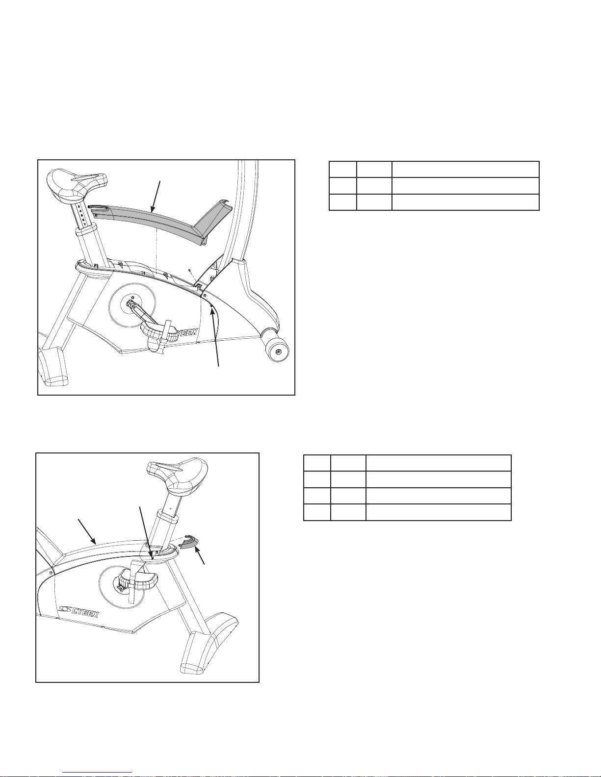
Installtopcap.
Install top cap with two screws using a Phillips screwdriver.
1
Item Description
1 Top cap
2 14 Screws (2)
2
Installbackcap.
1. Place the back cap into the top cap. Ensure the back cap is fully inserted into the top cap.
Item Description
1 Top cap
2
1
2 14 Screws (2)
3 Back cap
3
2. Install the back cap with two screws (#14) using a Phillips screwdriver.
18
Page 19
Cybex Owner’s Manual
Leveltheunit.
Conrm that the unit is on a level surface. If not, use a 9/16” open-end wrench to adjust the leveling
feet up or down.
Item Description
1 Leveling feet
1
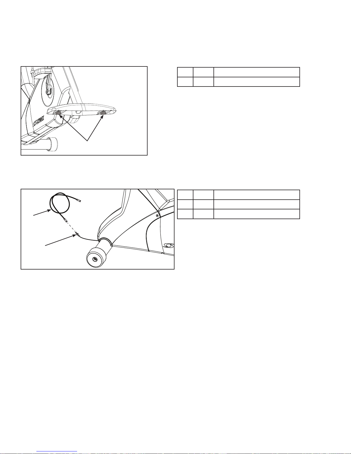
Install coax cable (E3 View Monitor option)
Install 6’ coax cable to the coax cable connector in base of unit.
Item Description
1 12 6’ coax cable
1
2 Coax cable connector
2
Visuallyinspecttheunit.
1. Examine the unit to ensure that the assembly is correct and complete.
2. Proceed to Testing the Operation section.
19
Page 20
Cybex Owner’s Manual
525R Assembly
Unpackandverifycontentsoftheunit.
Verify the following items are present. See Customer Service chapter for contact information if any
parts are missing.
Item Quantity Part Number Description
1 1 Varies Base with covers attached
2 1 Varies Console assembly
3 1 PL-21517 Front Left Cover
4 1 PL-21518 Front Right Cover
5 1 AX-21670 Seat Back Assembly
6 1 AX-21738 Accessory Tray
7 1 AX-21699 Hardware pack
8 1 LT-24303-4 Owner’s Manual
9 1 LT-24301 Assembly poster
10 1
10 1
10 1
11 1 Varies Power cord (E3 View Monitor option)
12 1 AW-23836 Cable, 6’, Coax (E3 View Monitor option)
LT-24291
LT-24292
LT-24293
Warranty sheet, Consumer
Warranty sheet, Commercial, Entry
Warranty sheet, Commercial, Full
7
8 9 10
11 12
3
2
6
5
1
4
20
Page 21
Cybex Owner’s Manual
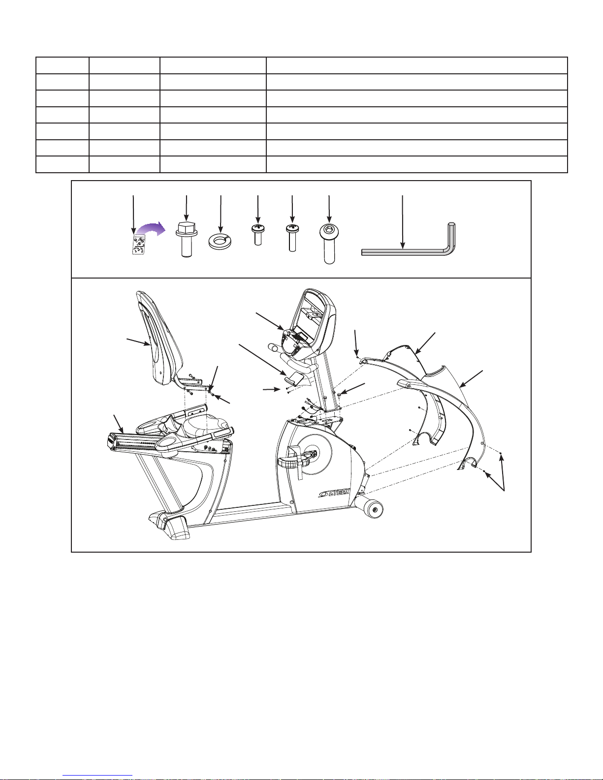
Item Quantity Part Number Description
13 4 HS-19108 Screw, 5/16-18 x .75”,HXHD,WHIZ-LOCK,GR5
14 4 HW-53018 Washer, 5/16” Split
15 6 HS-15706 Screw, 8-16 x .50”, PNHD
16 2 HS-18311 Screw, 8-16 x .75”, PNHD
17 4 HS-41107 Screw, 5/16-18 X 1.50”
18 1 HX-00438 3/16” Allen wrench
13 14 157 1716 18
2
15
5
6
3
14
NA
1
16
13
Lift and move the unit
1. Grasp the rear foot.
2. Lift the rear foot so the front transport wheels are able to roll on oor. Use proper lifting
methods.
4
15
3. Roll unit to intended location.
4. Lower the rear foot so unit is in intended location.
21
Page 22

Cybex Owner’s Manual
Installseatbackassembly.
1. Place the seat back assembly in the correct position and hand thread each of the screws and
four washers.
Item Description
1
1 Seat back assembly
2 14 Washers (4)
2
3 16 Screws (4)
3
2. Securely fasten the screws with the 3/16” Allen wrench provided.
Attachtheconsoleassemblytobaseassembly.
1. Hand thread two mounting screws into the base assembly.
Item Description
1
1 Console assembly
2 13 Screws (2)
3 Base assembly
2
3
The console assembly will need to be supported during steps 2 through 4.
22
Page 23

Cybex Owner’s Manual
2. Place the console assembly in the correct position on the base assembly by sliding into
position onto the two mounting screws.
Item Description
1
1 Console assembly
2 13 Screws (2)
2
3 Base assembly
3
3. Hand thread the other two screws.
4. Securely fasten the four screws with a 1/2” socket wrench.
5. Plug the upper display cable connector into the lower display cable connector. Ensure cable
connectors click together and are securely fastened.
Item Description
1
3
4
1 Upper display connector
2 Lower display connector
3 Upper heart rate connector
4 A/V cables, optional
2
5
5 Lower heart rate connector
6 Top hole in frame
6
6. Plug the upper heart rate connector into the lower heart rate connector.
7. Tuck each of the cable connectors into the top hole in the frame. Do not pinch or damage the
cables during assembly.
23
Page 24

Cybex Owner’s Manual
8. Connect the console cable’s DIN connector to the power supply output. Make sure the two
connectors snap rmly together and can not be pulled apart without pulling the sleeve back to
release it.
Item Description
1 Power supply outlet
2 Console cable DIN
connector
3 11 Power cord
1
3
2
Installthefrontcovers.
1. Install front right cover with three screws using a Phillips screwdriver.
Item Description
1 15 Screws (3)
2 Front right cover
1
2
In addition to two mounting screws per front cover, there are ve plastic connectors that secure the
front covers together. Ensure that all four plastic connectors are inserted properly in each front cover.
24
Page 25

Cybex Owner’s Manual
2. Install front left cover with three screws using a Phillips screwdriver.
Item Description
1 Plastic connectors
2 Front left cover
3 15 Screws (3)
1
3
2
Installtheaccessorytray.
1. Remove the two screws in the console assembly using a Phillips screwdriver.
Item Description
1 Accessory tray
2 Screws (2)
1
3 Console assembly
2
3
2. Install the accessory tray to the console assembly with the two screws removed in previous
step using a Phillips screwdriver.
25
Page 26

Cybex Owner’s Manual
Leveltheunit.
Conrm that the unit is on a level surface. If not, use a 9/16” open-end wrench to adjust the leveling
feet up or down.
Item Description
1 Leveling feet
1
Install coax cable (E3 View Monitor option)
Install 6’ coax cable to the coax cable connector in base of unit.
Item Description
1
1 12 6’ coax cable
2 Coax cable connector
2
Visuallyinspecttheunit.
1. Examine the unit to ensure that the assembly is correct and complete.
2. Proceed to Testing the Operation section.
26
Page 27

Cybex Owner’s Manual
Setup
Use the following instructions to setup the units settings.
1. Plug the optional power cord into a power outlet from a grounded circuit, See Electrical
Requirements. Coil up the remainder of the power cord and place it out of the way. If you do
not have the optional power supply, skip to step 3.
2. Verify the control panel will illuminate and is in Dormant Mode.
3. Hold the handrails to steady self while stepping into the pedals.
4. Begin pedaling.
TimeandDateconrmation
The rst time the unit is turned on, it prompts the user to conrm the current Time and Date. Quick
Start, Workouts, Setup or Stop will skip this requirement but it will appear again the next time the unit
is powered up until the time and date are properly set.
1. Press the ENTER key to begin editing the time, starting with the hours (HH) and then
minutes (MM) and then AM/PM/24.
2. Press the UP and DOWN keys to select the hour.
3. Press the ENTER key to accept and begin editing the minutes.
4. Press the UP and DOWN keys to select the minutes.
5. Press the ENTER key to accept and begin editing the AM/PM/24 hour setting.
6. Press the ENTER
key to accept time.
Continue this procedure for the Date. Date format is [YYYY] [MM] [DD]. Y - Year, M - Month and D -
Day.
7. Press the ENTER
key after the nal setting for Day. The opening screen will now be
displayed.
Time and Date conrmation complete.
27
Page 28

Setup options
REVISIONS
DESCRIPTION
See sheet 1
ECO
REV
D A TE APPRO V AL
BY
.
.
.
GLOSS AREAS
Cybex Owner’s Manual
1. Press and hold the SCAN
and UP keys for 3 seconds.
2. Navigate through the setup menu with the UP and DOWN keys.
3. Press the ENTER key once to enter setup values. Press again to save any changes
and advance forward in the menu.
The Setup options are:
LED Console E3 View Monitor
Time Set time display format AM, PM, or 24. Set time in Hours and Minutes HH:MM.
Date Year format is Y - Year [YYYY]. Date format is [YYYY] [MM] [DD]. Y -
Month format is M - Month [MM].
Year, M - Month, and D - Day.
Day format is D - Day [DD].
Weight and
Distance Units
LbS - Pounds, Kg - Kilograms or
Ston - Stone.
MI - Miles or KM - Kilometers.
LBS - Pounds, Kg - Kilograms or
Stone - Stone.
MI - Miles or KM - Kilometers.
Pause Set time length for Pause. OFF (Default), 0:30, 1:00, or 2:00 minutes.
Default Time Set default workout time. 10, 20, 30 (Default), or 60.
Max Time Set maximum workout time. OFF (Unlimited), 30, 60 (Default), 90,120 minutes
or Club*.
Quick Start Set Quick Start mode. Choices are Bike (Default) or Constant Power.
A/V Set A/V option. Choices are PEM, UHF, none, or FM (TF/M). See A/V Cong
and FM Radio Presets for full conguration. If unit ships with E3 View Monitor,
this setup option is skipped.
Sound Toggle console beeper On (Default) or
OFF. Set headphone speaker volume
0-30 (10 is default).
Toggle console beeper On (Default)
or OFF. Toggle headphone beeper
to Some (Default), All, or Off. Set
headphone speaker volume 0-30 (10
is default).
Languages Not available Set E3 View Monitor language.
Choices are: French, Spanish, or
English (Default).
*Club setting limits the workout time to 60 minutes during peak times. Peak times are 5:01 AM to
9:00 AM, and 4:01 PM to 9:00 PM
28
Page 29

Cybex Owner’s Manual
REVISIONS
DESCRIPTION
See sheet 1
ECO
REV
D A TE APPRO V AL
BY
.
.
.
GLOSS AREAS
REVISIONS
DESCRIPTION
See sheet 1
ECO
REV
D A TE APPRO V AL
BY
.
.
.
GLOSS AREAS
To reset setup options to default values
1. Press the SCAN
key at the rst setup option screen (Time). The console will display
“RESET” and “[dEFA] [ULtS] [? ]“.
To exit without resetting, press the ENTER key.
2. Press the SCAN
key to reset the console to the default values. The console will beep
twice and return to setup mode.
Exit Setup Mode.
Press the Stop key to exit Setup options.
A/V Config and FM Radio Presets
Setting up the optional Cybex Wireless Audio Receiver Module requires three steps:
• Determine the type of transmitter used (MYE 900MHz, Broadcast Vision 863MHz, etc. or TV FM).
• Assign a TV channel number to each transmitter on the console.
• Add FM radio station presets (optional)
Tools Required:
• Headphones (not included)
Determine transmitter type
There are two types of transmitters, UHF or TV FM. UHF transmitters will have TV identied by
number, example TV1. TV FM transmitters will have TV identied with FM frequencies,
example 93.1.
UHF Transmitters
TV1 TV2 TV3
Follow procedure:
Setup UHF Transmitters
For TV FM transmitters, record FM frequencies for all TV’s:
1 2 3 4 5 6 7 8 9 10
93.1 97.5 102.7
Follow procedure:
Setup TV FM Transmitters
TV FM Transmitters
29
Page 30

Cybex Owner’s Manual
REVISIONS
DESCRIPTION
See sheet 1
ECO
REV
D A TE APPRO V AL
BY
.
.
.
GLOSS AREAS
User Controls
1 2 3 4 5 6
8 119 10 12 137
1 Resistance keys Navigates through all stored channels as in User Mode
2 Gear/level display Shows setting of receiver sensitivity as (n)ear or (F)ar
3 Quick Start key Selects transmitter type Resets all stored TV channels when used
4 Workouts key Toggles setup for FM presets and back to TV channel setup
5 Resistance display Shows ‘FM’ when storing FM radio station presets
6 Resistance keys Toggles the display for Adding new channels or Deleting stored
channels
7 Volume keys Increase or decrease volume
8 Display option key Scans for available TV transmitters, or will seek the next strongest
FM station or FM transmitter frequency.
9 Headphone jack Plug in headphones to listen to channels
10 STOP key Stores and exits setup
11 Setup key When storing FM presets, this button will clear all stored FM radio
12 Enter key Enters menu, accepts value shown, moves forward in menu.
13 Up/Down keys Navigates TV channels or manually tunes FM frequencies
Set up UHF Transmitters
1. Press and hold Display option
setup.
2. Press Down to navigate to the A/V setup screen. Press the ENTER key.
3. Press the UP and DOWN keys to select “UHF”.
presets
Toggles near/far for UHF receiver sensitivity.
and Up for 3 seconds. Display will show time
30
Page 31

Cybex Owner’s Manual
REVISIONS
DESCRIPTION
See sheet 1
ECO
REV
D A TE APPRO V AL
BY
.
.
.
GLOSS AREAS
D
C
5
4
3
2
1
D
C
5
4
3
2
1
REVISIONS
DESCRIPTION
See sheet 1
ECO
REV
D A TE APPRO V AL
BY
.
.
.
GLOSS AREAS
4. Press the ENTER key.
5. Plug in headphones to listen for channels during setup.
Transmitter type display for LED consoles
900 MHz System 863 MHz System 806 MHz System
“M 900” MYE
“M 863” MYE “J1 806” Japan
14 channels
“C 900” Cardio
Theater
“E 900”
Enercise
“B 900”
Broadcast
Vision
6. Press Display option
seconds and then display channel number. Some of these channels may not be signals from
the TV transmitters and need to be deleted.
“E 863” Enercise
“J2 806” Japan
30 channels
“A 863”
Audeon
key to scan for available channels. The scan can take up to 10
Review channels
1. Press Up or Down to listen to available channels with the headphones.
2. Delete unwanted channels by pressing Resistance Up
LED window to [dEL]. Press Enter to delete channel. Repeat process for additional unwanted
channels.
3. Adjust the near/far setting if available channels are not showing. Press Setup key to change
the setting from “F” (Far) to “n” (Near). Press Display option
channels.
31
or Down
to change the right
to re-scan for available
Page 32

Cybex Owner’s Manual
REVISIONS
DESCRIPTION
See sheet 1
ECO
REV
D A TE APPRO V AL
BY
.
.
.
GLOSS AREAS
REVISIONS
DESCRIPTION
See sheet 1
ECO
REV
D A TE APPRO V AL
BY
.
.
.
GLOSS AREAS
D
C
5
4
3
2
1
D
C
5
4
3
2
1
REVISIONS
DESCRIPTION
See sheet 1
ECO
REV
D A TE APPRO V AL
BY
.
.
.
GLOSS AREAS
4. Press Up or Down to scroll through and verify all TV channels. If all TV transmitters
are stored, and they all correlate the TV number to the correct TV heard, setup is complete.
If not you may need to re-scan or adjust the transmitter codes (see documentation for your
transmitters to perform a code change).
5. Press Stop to exit setup.Transmitter setup complete.
6. Proceed to Add FM Radio Stations (optional).
Setup TV FM Transmitters
If your TV’s use FM transmitters, follow these instructions to assign a TV channel to each frequency.
1. Press and hold Display option
and Up for 3 seconds. Display will show time
setup.
2. Press Down to navigate to the A/V setup screen. Press the ENTER key.
3. Press the UP and DOWN keys to select “FM”.
4. Press the ENTER key.
5. Plug in headphones to listen for channels during setup.
6. Press Display option
to seek the next TV FM frequency or Up or Down to
tune manually.
7. Press Resistance Up
or Down
keys to add “[Add]” a channel. Press Enter to save
channel, “std” (stored) will be displayed.
8. Repeat steps 3 and 4 to add all TV FM channels.
9. Press Stop to exit setup when all the TV’s FM transmitter frequencies have a TV number.
Transmitter setup complete.
10.Proceed to Add FM Radio Stations (optional).
Add FM Radio Stations (optional)
If strong local FM Radio Stations are available in the area, you can set those as presets.
1. Enter A/V setup mode.
2. Press Workouts to display “FM” on the console. The left numeric will display “CH 1”.
3. Press Display option
manually.
to seek the next FM station or Up or Down to tune
32
Page 33

Cybex Owner’s Manual
D
C
5
4
3
2
1
D
C
5
4
3
2
1
4. Press Resistance Up
or Down
keys to add “[Add]” a channel. Press Enter to save
channel, “std” (stored) will be displayed.
5. Repeat steps 3 and 4 to save up to 32 FM radio stations.
6. Press Stop to exit setup when all FM radio stations are stored.
7. Press Up or Down to scroll through and verify all FM radio stations.
Adjust sound volumes
After completing setup, the sound volume should be adjusted between the TV transmitters and the
FM radio stations. If FM radio stations are not set, adjust volume between all TV’s.
1. Press Up or Down to select an FM radio station. This volume is not adjustable and is
the base volume.
2. Press Up or Down to select a TV station.
3. Adjust the volume of each TV to match an FM Radio Station or each other using the TV’s
remote control. The goal is for a volume setting of 10 on the treadmill to be the same for all TV
and FM channels.
4. Repeat procedure for all TV’s.
Setup complete
33
Page 34

Cybex Owner’s Manual
MUTE
POWER MUTE
TV/AV TV/FM CH LIST
OK
OK
E3 View Monitor Controls
The remote control is used to perform all setup operations for the E3 View Monitor.
POWER MUTE
SETUP TV/AV TV/FM CH LIST
SLEEP LAST
OK
ARC CC
PSM SSM SAP
1 2 3
4 5 6
7 8 9 0
TEXT SIZE INDEX REVEAL
i ?
HOLD MODE MIX UPDATE
X
SUBPAGE
POWER
SETUP
CH LIST
POWER Turn the E3 View monitor on or off
SETUP Enter or exit the Setup home screen
CH LIST Channel list - List all available
channels
CH▲ Channel up - Navigate up through the
on-screen menu
CH▼ Channel up - Navigate down through
the on-screen menu
VOL◄ Volume left - Navigate left through the
on-screen menu
VOL► Volume right - Navigate right through
the on-screen menu
34
Page 35

E3 View Monitor Setup
POWER MUTE
TV/AV TV/FM CH LIST
OK
OK
OK
Access Setup Screen
SETUP
Cybex Owner’s Manual
Press the SETUP
button to display the SETUP MODE screen on the E3 View Monitor. Follow
procedure to setup the E3 View Monitor.
■ Picture ►
■ Channels ►
■ Features ►
■ OSD Language English
Position: ▲ ▼
Exit: SETUP Next: ◄ ►
Picture
1. Press
2. Press
or
to select Picture.
to select access Picture menu.
SETUP MODE
3. Press
4. Press
or
or
Picture
■ Brightness 65
■ Contrast 70
■ Color 75
■ Tint 0
■ Color Temperature ►
■ Sharpness 60
■ Noise Reduction Enabled
■ HDMI Picture ►
Position: ▲ ▼
Exit: SETUP Next: ◄ ►
to select settings.
to adjust settings.
35
Page 36

Cybex Owner’s Manual
POWER MUTE
TV/AV TV/FM CH LIST
OK
OK
OK
Picture settings
Brightness Adjust range from 1 to 100. Default is 65.
Contrast Adjust range from 1 to 100. Default is 70.
Color Adjust range from 1 to 100. Default is 75.
Tint Adjust range from 1 to 100. Range is R50 to G50. Default is 0.
Color Temperature Adjust color balance of Red, Green and Blue temperatures.
Sharpness Adjust range from 1 to 100. Default is 60.
Noise Reduction Select Enabled (Default) or Disabled.
HDMI Picture Set to Auto or Adjust settings as needed. Available only when HDMI
signal is present.
SETUP
5. Press the SETUP
button to return to SETUP MODE menu.
Channels
1. Press
2. Press
or
to select Channels.
to select access Channels menu.
ATSC Monitor
Channels
■ Signal Cable STD
■ Auto Program ►
■ Add/Delete Channels ►
■ Parental Control ►
■ Default Channel Last
■ Channel Lock Disabled
■ Channel Memory Override Enabled
Position: ▲ ▼
Exit: SETUP Next: ◄ ►
DVB-T Monitor
Channels
■ Auto Program ►
■ Manual Program ►
■ Add/Delete Channels ►
■ Parental Control ►
■ Default Channel Last
■ Channel Lock Disabled
■ Channel Memory Override Enabled
Position: ▲ ▼
Exit: SETUP Next: ◄ ►
3. Press
4. Press
or
or
to select settings.
to adjust settings.
36
Page 37

Cybex Owner’s Manual
OK
OK
OK
OK
Channel settings
Signal (ATSC only) Select Air, Cable STD, Cable IRC, or Cable HRC.
Auto Program See Below
Manual Program
See Below
(DVB-T only)
Add/Delete Channels See Below
Parental Control Block channels based on TV ratings.
Default Channel Select channel to display on power up. Select from available channels or
last.
Channel Lock Select Enabled or Disabled. If enabled only one channel is shown, user
cannot change channels.
Channel Memory
Override
Select Enabled or Disabled. If enabled allows user to select any available
channel.
Auto Program (ATSC Monitor)
1. Press
2. Press
3. Press
to select Auto Program.
to enter the menu.
or
to select Mode.
■ Mode Analog Only
■ Channel Sequence Interleave A + D
■ Additional Digital Signal None
■ Channel Map Programmed ►
Position: ▲ ▼
Exit: SETUP Next: ◄ ►
ATSC Monitor
Auto Program
4. Press
• Analog Only (Default): TV searches for analog channels only.
• Digital Only: TV searches for digital channels only.
• Analog and Digital: TV searches for both analog and digital channels.
5. Press
or
to set the scope of channel scanning.
to select Channel Sequence.
37
Page 38

Cybex Owner’s Manual
OK
OK
OK
OK
OK
MUTE
POWER MUTE
TV/AV TV/FM CH LIST
POWER MUTE
TV/AV TV/FM CH LIST
6. Press
or
to set the Channel Sequence in which the channels are displayed after
searching.
• Interleave A+D: In the order of channel number regardless of the system.
• All A then D: Digital channels are displayed after all analog channels.
7. Press
or
to select Additional Digital Signal. Not available when Mode is set to
Analog Only.
8. Press
or
to choose the Additional Digital Signal source. Choices are: None, Air,
Cable STD, Cable IRC, or Cable HRC.
9. Press
10.Press
11.Press
to select Channel Map.
to start auto programming. A conrmation menu will appear before proceeding.
(Yes) to start auto programming. Press
(No) button to cancel the operation.
The TV will now search all available channels with an on-screen progress percentage
displayed. Any tuning Mode that includes Digital channels will require several minutes to
complete auto programming.
This may take 20 or more minutes. If screen shuts off, Press the POWER
on.
SETUP
12.Press the SETUP
button to return to normal TV viewing once auto programming is
complete.
CH LIST
13.Press the CHANNEL LIST
SETUP
14.Press the SETUP
button to return to SETUP MODE menu.
button to list programmed channels.
POWER
button to turn monitor
38
Page 39

Auto Program (DVB-T Monitor)
OK
OK
OK
OK
OK
OK
Cybex Owner’s Manual
1. Tap
2. Tap
3. Tap
to select Auto Program.
to enter the menu.
or
to select Country.
■ Country ---
■ Mode Analog Only
■ Channel Map Blank ►
Position: ▲ ▼
Exit: SETUP Next: ◄ ►
DVB-T Monitor
Auto Program
Available countries are:
Albania, Austria, Australia, Belgium, Bosnia, Bulgaria, China, Croatia, Czech, Denmark, Estonia,
Finland, France, Germany, Greece, Hungary, Ireland, Italy, Kazakhstan, Latvia, Lithuania,
Luxembourg, Moroco, Netherlands, Norway, Poland, Portugal, Romania, Russia, Serbia, Slovakia,
Slovenia, Spain, Sweden, Switzerland, Turkey, Uk, and Ukraine.
4. Tap
5. Tap
• Analog Only (Default): TV searches for analog channels only.
• Digital Only: TV searches for digital channels only.
• Analog and Digital: TV searches for both analog and digital channels.
6. Tap
7. Tap
or
or
to select Mode.
to set the scope of channel scanning.
to select Channel Map.
to start auto programming. A conrmation menu will appear before proceeding.
8. Tap
(Yes) to start auto programming. Tap
TV will now search all available channels with an on-screen progress percentage displayed.
Any tuning Mode that includes Digital channels will require several minutes to complete auto
programming.
(No) button to cancel the operation. The
39
Page 40

Cybex Owner’s Manual
MUTE
POWER MUTE
TV/AV TV/FM CH LIST
POWER MUTE
TV/AV TV/FM CH LIST
OK
OK
POWER
This may take 20 or more minutes. If screen shuts off, POWER
SETUP
9. Press the SETUP
button to return to normal TV viewing once auto programming is
complete.
CH LIST
10.Tap the CHANNEL LIST
SETUP
11.Press the SETUP
button to return to SETUP MODE menu.
button to list programmed channels.
Manual Program (ATSC and DVB-T)
1. Tap
2. Tap
3. Tap
to select Manual Program.
to enter the menu.
or
to select Mode.
■ Mode ATV
■ Conrmation ►
Manual Program
button to turn monitor on.
Position: ▲ ▼
Exit: SETUP Next: ◄ ►
40
Page 41

Cybex Owner’s Manual
OK
OK
OK
OK
4. Tap
■ Storage 1
■ System BG
■ Band V/UHF
■ Channel 1
■ Name C 01
■ Search ◄ ►
■ Save ►
Position: ▲ ▼
Exit: SETUP Next: ◄ ►
or
ATV Manual Program
to select ATV or DTV.
DTV Manual Program
■ UHF CH. ►
■ Save 21
Bad Nor. Good
Signal Strength
Signal Quality
Position: ▲ ▼
Exit: SETUP Next: ◄ ►
ATV Mode Adjust settings for Storage, System, Band, Channel, Name, or Search. Select
Save to save settings.
DTV Mode Select UHF channel. Select Save to save settings.
Add/Delete Channels (ATSC and DVB-T)
1. Press
2. Press
to select Add/Delete Channels.
to enter the Add/Delete Channels menu.
Add/Delete Channels
■ Analog Channel 2
■ Add/Delete Analog Channel Added
■ Enable/Disable Digital Channel ►
Position: ▲ ▼
Exit: SETUP Next: ◄ ►
To add or delete an analog channel perform the following procedure. To enable or disable digital
channels, go to step 7.
3. Press
4. Press
or
or
to select the desired analog channel.
to highlight Add/Delete Analog Channel.
41
Page 42

Cybex Owner’s Manual
OK
POWER MUTE
TV/AV TV/FM CH LIST
POWER MUTE
TV/AV TV/FM CH LIST
OK
OK
OK
POWER MUTE
TV/AV TV/FM CH LIST
OK
OK
OK
5. Press
6. Press the SETUP
or
to select Added or Deleted.
SETUP
button to return to the previous menu. To exit, Press the SETUP
button until the programming menus disappear. If there are more analog channels to be added
or deleted, repeat steps 3 through 5.
7. Press
8. Press
or
to highlight Enable/Disable Digital Channel.
to select Enable/Disable Digital Channel. If there are not any channels
programmed in the Service Level, “No Channels Present” will appear in the menu.
9. Press
10.Press
11.Press the SETUP
or
or
to highlight the digital channel that needs to be enabled or disabled.
to select Enable or Disable.
SETUP
button to return to the previous menu.
SETUP
Features
1. Press
2. Press
or
to select Features.
to select access Features menu.
ATSC Monitor
Features
■ Power on Captions Mode Last
■ Digital Mode Time Setup ►
■ Diagnostics ►
■ Caption Text Modes Disabled
Position: ▲ ▼
Exit: SETUP Next: ◄ ►
DVB-T Monitor
Features
■ Power on Subtitles Mode Last
■ Digital Mode Time Setup ►
■ Diagnostics ►
Position: ▲ ▼
Exit: SETUP Next: ◄ ►
3. Press
4. Press
or
or
to select settings.
to adjust settings.
42
Page 43

Feature settings
POWER MUTE
TV/AV TV/FM CH LIST
OK
OK
POWER MUTE
TV/AV TV/FM CH LIST
POWER MUTE
TV/AV TV/FM CH LIST
Cybex Owner’s Manual
Power on Captions Mode
Select Off or Last. Last will set caption mode to last used setting.
(ATSC only)
Power on Subtitles Mode
Select Off or Last. Last will set subtitle mode to last used setting.
(DVB-T only)
Digital Mode Time Setup Set current time automatically from digital signal. Select time zone
and daylight savings time to Auto, On, or Off.
Diagnostics Provides diagnostic information only. Settings cannot be changed.
Caption Text Modes (ATSC
Select Enabled or Disabled.
only)
SETUP
5. Press the SETUP
button to return to SETUP MODE menu.
OSD Language
1. Press
2. Press
or
or
to select OSD Language.
to select language.
ATSC choices English, Français or Español.
DVB-T choices English, Français, Español, Dutch, Danish, Russian, German, and Swedish.
SETUP
3. Press the SETUP
button to return to SETUP MODE menu.
Exit Set Up Mode by pressing the SETUP
Setup Complete
SETUP
button.
43
Page 44

Cybex Owner’s Manual
Testing the Operation
Use the following instructions to test the full resistance range of the unit:
1. Plug the optional power cord into a power outlet from a grounded circuit, See Electrical
Requirements. Coil up the remainder of the power cord and place it out of the way. If you do
not have the optional power supply, skip to step 3.
2. Verify the control panel will illuminate and is in Dormant Mode.
3. Hold the handrails to steady self while stepping into the pedals.
4. Begin pedaling.
5. Press the Quick Start key.
6. Run unit through full resistance range. First press the RESISTANCE + key until unit reaches
its highest load (the display will show “21”). Then press the RESISTANCE - key until unit
reaches its lowest load (the display will show “1”). The resistance should increase and
decrease while pedaling.
When unit reaches the set resistance, the displays will stop ashing and remain steadily illuminated to
indicate the desired setting has been reached.
7. Wait until pedals come to a complete stop before dismounting the unit. Hold the handrails to
steady self while stepping off the unit.
44
Page 45

Cybex Owner’s Manual
Operation
Intended Use
The intended use of this exercise equipment is to aid or improve general physical tness and
exercise.
Terms Used
Active Mode – Any time unit is controlling resistance and accumulating workout data. Active Mode
begins after hitting QUICK START during the initial count-down screen, after completing the setup for
a workout or by default if the initial count-down screen times out and enters Quick Start Manual mode.
Auto-Scan – Display automatically cycles through workout data.
Cool Down – A reduction of work load for a short duration allows user to gently reduce heart rate.
Cool Down occurs two minutes prior to completion of the workout-controlled workout sessions.
Dormant Mode – Occurs only when a unit is plugged in using the optional AC adapter and is not in
use.
Isokinetic Exercise – Accommodating resistance, where unit provides a corresponding amount
of resistance on the user to keep them at a xed pedal speed. Such exercise is used to test and
improve muscular strength and endurance, especially after injury.
Manual Mode – The unit defaults to this mode if not in a workout. Manual Mode allows user to adjust
the gear (1-21) and pedal at any speed, simulating a road bike. Time will count up in Quick Start,
Manual or Count Down to the chosen session time if user enters a TIME or selects the ENTER button
and completes setup.
Pause Mode – Occurs only if the Pause feature is enabled and user selects the STOP key from
Active Mode.
Workout Setup Mode – Begins after pressing WORKOUTS or ADVANCED key. Upon entering a
workout, user is prompted to adjust the appropriate settings.
Quick Start – By default, the unit will end up in Quick Start Manual Mode if the user begins pedalling
and allows the 5 second count-down to end. Also choose the QUICK START button to enter into
Quick Start Manual Mode, where the user controls the gear selection and time is counting up.
Workout Review – Review of the accumulated workout data and/or the results of the Fitness Test will
happen at the end of each workout session.
Read and understand all warnings and cautions in the Safety Section and all operation
instructions in this chapter before operating unit.
45
Page 46

Cybex Owner’s Manual
User Control Symbols Used
Control Control Name Description
RESISTANCE UP Adjust Resistance up.
RESISTANCE DOWN Adjust Resistance down.
VOLUME UP Adjust Volume up.
VOLUME DOWN Adjust Volume down.
UP KEY
Adjust Time, Level, Weight, or Workout up.
A/V - Channel UP.
iPod/iPhone/iPad - NEXT track (option)
DOWN KEY
Adjust Time, Level, Weight, or Workout down.
A/V - Channel DOWN.
iPod/iPhone/iPad - PREVIOUS track (option)
STOP
If pause feature is enabled, press STOP once to enter
pause mode.
46
Page 47

Console Display
1
2
3
Cybex Owner’s Manual
LED Display
4
5
1 Left enunciator Displays Time, BPM, or Weight.
2 Left data readout Displays value of Time, BPM, or Weight.
3 Bar graph Displays workout proles and setup options.
4 Right enunciator Displays Calories, RPM, or Cal/Hour.
5 Right data readout Displays value of Calories, RPM, or Cal/Hour.
E3 View LCD Display
47
Page 48

User Controls
1 2 3 4 5 6
Cybex Owner’s Manual
8 119 10 12 137
1 Resistance keys 6 Resistance keys 11 Setup key
2 Gear/level display 7 Volume keys 12 Enter key
3 Quick Start key 8 Display option key 13 Up/Down keys
4 Workouts key 9 Headphone jack
5 Resistance display 10 STOP key
Displays — Gear, Level, and Resistance is shown in the LED displays. The Up/Down LED indicates
when Up/Down keys are active to change settings.
Keys — User controls for Quick Start, Workouts, Resistance, Volume, Scan, Stop, Setup, Enter and
Up/Down.
Mount and Dismount
To mount unit safely:
1. Verify unit is in Dormant Mode and pedals are completely stopped.
2. Grasp handrail and step carefully onto pedals.
To dismount unit safely:
1. Wait until pedals come to a complete stop.
2. Grasp handrails for support and carefully step off unit.
48
Page 49

Cybex Owner’s Manual
Emergency Dismount
If experiencing pain, feeling faint or needing to stop unit in an emergency situation:
1. Grasp handrails for support.
2. Stop pedalling.
3. Continue holding the handrails while carefully stepping off the unit.
Quick Operation Guide
Maximum user weight is 400 lbs. (181 kg).
The following is a quick overview of the operation of the unit. For more information read Detailed
Operation Guide in this chapter.
1. Verify pedals are completely stopped.
2. Grasp handrails and step carefully into pedals. Begin pedaling.
3. Press the Quick Start key. The console will beep for one second and display “GO!”.
4. Press the UP and DOWN keys to increase or decrease weight.
5. Press the ENTER
key to enter weight.
6. Press the Resistance + – keys to change the resistance at any time.
7. Press the Stop key at any time to pause. “Workout Review” is displayed.
Detailed Operation Guide
Maximum user weight is 400 lbs. (181 kg).
1. Plug the optional power cord into a power outlet from a grounded circuit, See Electrical
Requirements. Coil up the remainder of the power cord and place it out of the way. The
control panel will light up and be in the Dormant Mode.
2. Verify pedals are completely stopped.
3. Grasp handrails and step carefully into pedals. Begin pedaling.
4. Select Quick Start or Workouts.
If Quick Start is selected, The console will beep for one second, display “GO!”, and enter Active
Mode.
49
Page 50

Cybex Owner’s Manual
If Workouts is selected, Select a workout and setup options.
1. Select workouts 1 through 9 with the UP and DOWN keys.
2. Press the ENTER key to advance to setup options.
Setup options:
Workouts 1 through 8 Time, Level, Weight
Heart Rate Control (E3 View Monitor monitor
Time, Weight, Age, Target Heart Rate
option)*
*The Heart Rate Control workout requires wearing a Polar® compatible chest strap (not included).
3. Press the UP
and DOWN keys to increase or decrease each of the setup options.
Press the ENTER key to advance to the next option.
For the most accurate resistance and calorie count, you must set your correct weight before
beginning your workout (including clothing). Valid weight range is 50 - 400 lbs, 23-181 kgs, or 3.6-
28.6 stones.
When selecting a workout you must press the Enter
key after each adjustment of Time, Level,
Weight. E3 View Monitor models include age selection.
After nal selection has been made the console will beep for one second, display “GO!”, and enter
Active Mode.
4. Begin pedaling.
5. Observe the control panel. The top center Bar Graph display shows a graphical representation
of the relative MET level, and if in a program, will show the relative intensity changes that are
coming up. The Data Readouts will start showing the workout data such as Distance, Calories,
Heart rate (if available), MET and Time. The data displays will start by automatically shifting
every 5 seconds.
Heart rate will be displayed in lieu of MET if a valid heart rate is available from a wireless chest strap
(not included) or by holding the contact heart rate grips.
When you adjust resistance in a workout, the change will affect only the current segment. The
workout control will resume starting with the next segment. To increase or decrease overall intensity,
adjust the resistance and/or the workout level.
6. Press the Resistance + – keys to change the resistance at any time. The display will show the
current gear or watt level. Gear range is 1-21, watt level range is 20-500.
7. Press the Stop key at any time to pause. “Workout Review” is displayed.
When a workout is complete the unit begins a countdown, “3...2...1” and sounds a tone for each
count. Workout Review is displayed for the preset time or until you press the Stop key. The unit
returns to Dormant Mode.
50
Page 51

Cybex Owner’s Manual
Workout Selection
With the 525C and 525R you may choose from Quick Start, or nine workout choices. Speed is never
predetermined. Change speed by changing stride.
Workout Choices:
Workout Levels Settings
1 Weight Loss 21 Select time, level and weight.
2 Rolling Hills 21 Select time, level and weight.
3 Hills 21 Select time, level and weight.
4 Pike’s Peak 21 Select time, level and weight.
5 Ramps 21 Select time, level and weight.
6 Interval 21 Select time, level and weight.
7 Strength 21 Select time, level and weight.
8 Cardio 21 Select time, level and weight.
9 Heart Rate Control (HRC)
(E3 View Monitor monitor option)
NA Select time, age, target heart rate and weight.
Navigation
The keypad is active during the workout setup time to key in time, level and weight values. The
Resistance + - keys are also active to adjust the displayed workout value (up or down). Hold down
key to accelerate rate of increments.
Press the ENTER
key after each step to accept values entered and to move forward in the
setup process.
The QUICK START key may be pressed any time during this process to accept all workout defaults.
If no activity is performed after a workout is selected, the unit will default to the settings of the current
workout selected.
See Appendix for Workout Overviews
51
Page 52

Cybex Owner’s Manual
Data Readouts
As the user exercises, the unit keeps track of and displays the following data:
BPM (Beats per Minute) – User’s current heart rate. Heart rate will appear when a signal is
®
introduced. Use either the hand grips for Contact Heart Rate or a Polar
compatible heart rate
transmitter.
Calories – The total accumulated calories burned during workout.
Calories Per Hour – Calculation of present workloads energy exertion in Calories per Hour.
RPM (Rotation Per Minute) – User’s crank rotations per minute.
Time – The total time you’ve been working out or time remaining. Display time as hours:minutes.
Weight – During setup, display WEIGHT value.
Heart Rate Indicator
Contact Heart Rate – Lightly hold hand grips on the handlebar ensuring that hands are clean and
contact both the front and back sensors of each grip. A heart rate will display in typically 30 seconds
or less.
Factors that interfere with heart rate signal:
• hand lotions
• oils or body powder
• excessive dirt
• excessive movement
• body composition
• hydration
• too loose grip
• too tight grip
• resting or leaning on grips
Wireless Heart Rate – To use this feature, a Polar® compatible heart rate transmitter belt (not
included) must be worn.
Once the actual heart rate is determined, the LED to the right of the Data Readouts is blinking to the
displayed BPM and the Heart LED lights up. The color of the light represents a scale of low to high
target heart rate.
Blue 0 – 69 BPM
Green 70 – 93 BPM
Yellow 94 – 119 BPM
Blood Orange 120 – 169
Magenta 170 and higher
52
Page 53

Cybex Owner’s Manual
REVISIONS
DESCRIPTION
See sheet 1
ECO
REV
D A TE APPRO V AL
BY
.
.
.
GLOSS AREAS
REVISIONS
DESCRIPTION
See sheet 1
ECO
REV
D A TE APPRO V AL
BY
.
.
.
GLOSS AREAS
E3 View Monitor Monitor Screen Options
During operation four E3 View Monitor screen options are available. Press SCAN
screens. The SCAN
LED’s will indicate display option.
to change
TV + Data Display video with data at bottom of screen
LED I on
TV Only Display video only
LED II on
Data Only Display data only
LED III on
Blank Screen is blank, video and data are not displayed
No LED’s on
iPod/iPhone/iPad Functions
Connecting iPod/iPhone/iPad — Connecting an iPod/iPhone/iPad allows some control through the
keypad. The iPod/iPhone/iPad will not be charged while connected.
1. Connect iPod/iPhone/iPad (not supplied) into the 30 pin connector.
2. Place iPod/iPhone/iPad onto the accessory tray.
3. Plug headphones (not supplied) into the console headphone jack.
4. Press volume Up
or Down to adjust volume.
5. For non-E3 View Monitor consoles, press the UP and DOWN keys to change tracks.
Videos will not be displayed on the E3 View Monitor.
Battery Sentry
Battery Sentry uses display feedback (speed signal or key presses) to determine user presence. If a
user is not detected within 10 seconds, the display beeps and inquires “run?”.
Resume pedalling or press any key within a pre-selected time to resume workout.
53
Page 54

Maintenance
All preventive maintenance activities must be performed on a regular basis. Performing routine
preventive maintenance actions can aid in providing safe, trouble-free operation of all Cybex
equipment.
Cybex is not responsible for performing regular inspection and maintenance actions for your
machines. Instruct all personnel in equipment inspection and maintenance actions and also in
accident reporting/recording. Cybex representatives are available to answer any questions that you
may have.
WARNING: For maintenance, service and repair:
• Must be performed by trained personnel only
• Use only Cybex replacement parts
• Unplug unit before working on it
• Keep water and liquids away from electrical parts.
Warnings
Read all warnings in this chapter.
Observe the following warnings:
DANGER: Electrocution hazard.
To avoid death or serious injury unplug unit when not in use or when performing
maintenance.
WARNING: Equipment hazard.
To avoid serious injury or death replace worn or damaged components immediately
and keep the equipment out of use until repair is completed.
Page 55

Cybex Owner’s Manual
Preventive Maintenance Activities
Perform regular preventive maintenance to ensure normal operation of unit. Keep a log of all
maintenance actions to assist in staying current with all preventive maintenance activities.
Cybex is not responsible for performing regular inspection and maintenance actions for your unit.
Instruct all personnel in equipment inspection and maintenance actions and also in accident reporting/
recording. Contact Cybex Customer Service at 888-462-9239 or 508-533-4300 for any preventive
maintenance or service concerns.
Read and understand warnings listed in this chapter and in the Safety Section. Read and
understand all instructions in this section.
During maintenance, disconnect the external power source. If unit has the optional AC Power Kit
unplug the power cord from the power outlet.
Cleaning Unit
1. Spray a clean cloth with a mild cleaning agent, such as a water and dish soap solution.
2. Wipe unit.
Do not spray cleaning solution directly on unit. Direct spraying could cause damage to electronics and
may void warranty.
After Each Use:
• Wipe up any liquid spills immediately.
• Wipe up any remaining perspiration from handles and painted surfaces.
• Be careful not to spill or get excessive moisture on the console and display overlays, as this might
create an electrical hazard or cause failure of the electronics.
• Clean heart rate grips using a cloth dampened with a cleaning solution containing alcohol.
The heart rate grips are the only part of the unit where a cleaning solution containing alcohol should
be used.
55
Page 56

Rechargeable Battery
The unit is designed with a 12 volt Lead-Acid rechargeable battery. The battery will recharge during
regular operation of unit or when the optional power adapter is plugged in.
The display will indicate dashes in the left display if the battery fails to provide enough energy.
If the battery is completely discharged, the workout review will also be truncated if the user is not
striding during the time period. See Customer Service for contact information to replace the battery or
purchase the optional AC adapter kit.
Battery replacement must be performed only by qualied technician.
Remove battery and dispose of safely before unit disposal.
E3 View Monitor
Cleaning
1. Unplug power cord from the wall socket.
2. Dust off the panel with a soft dry cloth as needed. The screen can be cleaned with computer
screen wipes or other non-abrasive, moist, disposable wipes.
Storage or Long Non-Use Periods
When not using product for an extended period of time the product should be disconnected from the
Power Supply, TV/Cable Signal Feed, and any Peripheral Devices.
Pixels
Very small red, blue, white or green spots may be visible or may appear on the screen. This is a
characteristic of liquid crystal display panels and is not a faulty condition. The liquid crystal panel is
built with very high precision technology giving ne picture details. Occasionally, a few non-active
pixels may appear on the screen as a xed point. This does not affect the performance of monitor or
merit a warranty claim.
Maintenance
• It is very important to have the unit regularly examined by a qualied technician to ensure the
product is t for use.
• If the unit malfunctions, please refer to a qualied technician for repair or replacement of defective
parts immediately. Do not attempt to use the monitor until it has been inspected and repaired by a
qualied technician.
• For inspection, installation and servicing, please consult qualied technician.
• Failure to use a manufacturer approved repair technician may void any warranty claims.
Page 57

Cybex Owner’s Manual
Environment
Humidity and Static Electricity
The unit is designed to function normally in an environment with a relative humidity range of 30% to
75%. The unit can be shipped and stored in a relative humidity range of 10% to 90%.
Climatic dry air may cause static electricity. During workout, user may experience a shock due
to build up of static electricity on the body and the discharge path of the unit. If static electricity is
experienced, increase humidity to a comfortable level through the use of a humidier.
Do not install, use or store the unit in an area of high humidity, such as in the vicinity of a steam room,
sauna, indoor pool or outdoors. Exposure to extensive water vapor, chlorine
and/or bromine could adversely affect the electronics as well as other parts of the unit.
Temperature
The unit is designed to function normally in an environment with an ambient temperature range of
50° F (10° C) to 104° F (40° C). The unit can be shipped and stored in an environment with an
ambient temperature range of 32° F (0° C) to 140° F (60° C).
57
Page 58

Cybex Owner’s Manual
Customer Service
Product Registration
To register product do the following:
1. Visit www.cybexintl.com.
2. Locate Product Registration in the Support section.
3. Fill out form completely.
4. Click the Submit button to register product.
Contacting Service
Hours of phone service are Monday through Friday from 8:30 a.m. to 6:00 p.m. Eastern Standard
Time.
For Cybex customers living in the USA, contact Cybex Customer Service at 888-462-9239.
For Cybex customers living outside the USA, contact Cybex Customer Service at 508-533-4300 or
fax 508-533-5183. Email address internationaltechhelp@cybexintl.com
Find information on the web at www.cybexintl.com.
To contact us online go to www.cybexintl.com.
Ordering Parts
To order parts online go to www.cybexintl.com.
To speak with a customer service representative, call 888-462-9239 (for customers living within the
USA) or 508-533-4300 (for customers outside the USA).
The following information located on the serial number decal will assist our Cybex representatives in
serving you.
• Unit Serial Number, Product Name and Model Number
• Part Description and Part Number if you have it. All parts can be found on the web at
www.cybexintl.com
• Shipping Address
• Contact Name
• Include a description of the problem.
In addition to your shipping address and contact name, your account number is helpful but not
required. You may also fax orders to 508-533-5183.
58
Page 59

Cybex Owner’s Manual
Return Material Authorization (RMA)
The Return Material Authorization (RMA) system is used when returning material for placement,
repair or credit. The system assures that returned materials are properly handled and analyzed.
Follow the following procedures carefully.
Contact your authorized Cybex dealer on all warranty-related matters. Your local Cybex dealer will
request a RMA from Cybex, if applicable. Under no circumstances will defective parts or equipment
be accepted by Cybex without proper RMA and an Automated Return Service (ARS) label.
Please contact Cybex Customer Service for the return of any item that is defective.
Provide the technician with a detailed description of the problem you are having or the defect in the
item you wish to return. Provide the model and serial number of your Cybex equipment.
At Cybex’s discretion, the technician may request that you return the problem part(s) to Cybex for
evaluation and repair or replacement. The technician will assign you a RMA number and will send
you an ARS label. The ARS label and the RMA numbers must be clearly displayed on the outside of
the package that contains the item(s) to be returned. Include the description of the problem, the serial
number of the equipment and the name and address of the owner in the package along with the
part(s).
Merchandise returned without an RMA number on the outside of the package or shipments sent COD
will not be accepted by the Cybex receiving department.
Damaged Parts
Materials damaged in shipment should not be returned for credit. Shipping damages are the
responsibility of the carrier (UPS, Federal Express, trucking companies, etc.)
Apparent Damage
Upon receipt of your shipment, check all items carefully. Any damage seen with a visual check must
be noted on the freight bill and signed by the carrier’s agent. Failure to do so will result in the carriers
refusal to honor your damage claim. The carrier will provide you with the required forms for ling such
claims.
Concealed Damage
Damage not seen with a visual check upon receipt of a shipment but notices later must be reported
to the carrier as soon as possible. Upon discovery of the damage, a written or phone request to
the carrier asking them to perform an inspection of the materials must be made within ten days of
the delivery date. Keep all shipping containers and packing materials as they will be needed in the
inspection process. The carrier will provide you with an inspection report and the necessary forms for
ling a concealed damage claim. Concealed damage claim is the carrier’s responsibility.
59 PB
Page 60

Cybex Owner’s Manual
Appendix - Workout Overviews
1 - Weight Loss
The Weight Loss workout is designed for low to medium intensity training that the user can sustain
for an extended period of time. It uses a low intensity resistance baseline for its two and a half
minute core workout with forty-ve second periods of higher resistance. The constant variety
provides for periods of higher expenditure and training effect without the introduction of undue fatigue
allowing the user to perform for longer periods of time.
Watt per level/gear
Time :30 :30 :30 :30 :45 :30 :30 :45 :45 :45 :30
Warm Up Core Segments Cool Down
Level 1 2 3 4 1 2 3 4 1 2 3
21
20
19
18
17
16
15
14
13
12
11
10
9
8
7
6
5
4
3
2
1
50 100 150 200 250 150 100 150 150 100 50
50 90 135 180 225 135 90 135 135 90 50
50 90 130 175 220 130 90 130 130 90 50
50 85 125 165 205 125 85 125 125 85 50
45 80 115 155 195 115 80 115 115 80 45
45 80 115 150 190 115 80 11 5 115 80 45
45 75 105 140 175 105 75 105 105 75 45
45 75 105 135 170 105 75 105 105 75 45
40 65 90 120 150 90 65 90 90 65 40
40 60 85 110 140 85 60 85 85 60 40
40 60 80 105 130 80 60 80 80 60 40
40 60 80 100 125 80 60 80 80 60 40
40 55 75 95 115 75 55 75 75 55 40
35 50 65 85 105 65 50 65 65 50 35
35 45 60 75 95 60 45 60 60 45 35
35 45 55 70 85 55 45 55 55 45 35
35 45 55 65 80 55 45 55 55 45 35
30 35 45 55 65 45 35 45 45 35 30
30 35 40 50 60 40 35 40 40 35 30
30 35 40 45 55 40 35 40 40 35 30
30 35 40 45 50 40 35 40 40 35 30
60
Page 61

Cybex Owner’s Manual
2 - Rolling Hills
The Rolling Hills workout is a two and a half-minute core workout designed to give the users the
experience of riding constantly rolling hills without the steep grades of the Hills workout. Users will
ride at a lower intensity with twice as much time spent at each resistance level and a two-minute rest
period before the core workout repeats.
Watt per level/gear
Time :30 :30 :30 :30 :15 1:00 :45 :30 :45 :45 :30
Warm Up Core Segments Cool Down
Level 1 2 3 4 1 2 3 4 1 2 3
21
20
19
18
17
16
15
14
13
12
11
10
9
8
7
6
5
4
3
2
1
50 100 150 200 100 150 250 150 150 100 50
50 90 135 180 90 135 225 135 135 90 50
50 90 130 175 90 130 220 130 130 90 50
50 85 125 165 85 125 205 125 125 85 50
45 80 115 155 80 115 195 115 115 80 45
45 80 115 150 80 115 190 115 115 80 45
45 75 105 140 75 105 175 105 105 75 45
45 75 105 135 75 105 170 105 105 75 45
40 65 90 120 65 90 150 90 90 65 40
40 60 85 110 60 85 140 85 85 60 40
40 60 80 105 60 80 130 80 80 60 40
40 60 80 100 60 80 125 80 80 60 40
40 55 75 95 55 75 115 75 75 55 40
35 50 65 85 50 65 105 65 65 50 35
35 45 60 75 45 60 95 60 60 45 35
35 45 55 70 45 55 85 55 55 45 35
35 45 55 65 45 55 80 55 55 45 35
30 35 45 55 35 45 65 45 45 35 30
30 35 40 50 35 40 60 40 40 35 30
30 35 40 45 35 40 55 40 40 35 30
30 35 40 45 35 40 50 40 40 35 30
61
Page 62

Cybex Owner’s Manual
3 - Hills
The Hills workout is a three-minute core workout designed to give the user an intense interval
workout. Users will experience intervals of moderate resistance at the beginning to simulate the start
of the climb and will deliver peak resistance after two and a half minutes. The resistance then returns
to the preliminary level and the core workout repeats itself.
Watt per level/gear
Time :30 :30 :30 :30 :30 :30 :30 :15 :15 :30 :15 :15 :45 :45 :30
Warm Up Core Segments Cool Down
Level 1 2 3 4 1 2 3 4 5 6 7 8 1 2 3
21
20
50 100 150 200 250 300 350 300 350 400 350 300 150 100 50
50 90 135 180 225 275 325 275 325 375 325 275 135 90 50
19
18
17
16
15
14
13
12
11
10
9
8
7
6
5
4
3
2
1
50 90 130 175 220 265 315 265 315 365 315 265 130 90 50
50 85 125 165 205 250 295 250 295 345 295 250 125 85 50
45 80 115 155 195 235 280 235 280 325 280 235 115 80 45
45 80 115 150 190 230 270 230 270 315 270 230 115 80 45
45 75 105 140 175 215 255 215 255 300 255 215 105 75 45
45 75 105 135 170 205 245 205 245 285 245 205 105 75 45
40 65 90 120 150 185 220 185 220 260 220 185 90 65 40
40 60 85 110 140 170 205 170 205 240 205 170 85 60 40
40 60 80 105 130 160 190 160 190 225 190 160 80 60 40
40 60 80 100 125 150 180 150 180 210 180 150 80 60 40
40 55 75 95 115 140 165 140 165 195 165 140 75 55 40
35 50 65 85 105 125 150 125 150 175 150 125 65 50 35
35 45 60 75 95 115 135 115 135 160 135 115 60 45 35
35 45 55 70 85 105 125 105 125 145 125 105 55 45 35
35 45 55 65 80 95 11 5 95 115 135 115 95 55 45 35
30 35 45 55 65 80 95 80 95 115 95 80 45 35 30
30 35 40 50 60 70 85 70 85 100 85 70 40 35 30
30 35 40 45 55 65 75 65 75 90 75 65 40 35 30
30 35 40 45 50 60 70 60 70 85 70 60 40 35 30
62
Page 63

Cybex Owner’s Manual
4 - Pike’s Peak
Pikes Peak is a three-minute fteen-second core workout that begins at a low intensity level and
incrementally climbs to peak resistance after one and a half-minutes and remains at that level for 45
seconds before ramping back down to the initial level. The repetitive workout is designed to keep the
user in an aerobic state before reaching their anaerobic threshold.
Watt per level/gear
Time :30 :30 :30 :30 :15 :15 :15 :15 :15 :45 :15 :15 :15 :15 :15 :45 :45 :30
Warm Up Core Segments Cool Down
Level 1 2 3 4 1 2 3 4 5 6 7 8 9 10 11 1 2 3
21
50 100 150 200 100 150 250 300 350 400 350 300 250 150 100 150 100 50
20
19
18
17
16
15
14
13
12
11
10
9
8
7
6
5
4
3
2
1
50 90 135 180 90 135 225 275 325 375 325 275 225 135 90 135 90 50
50 90 130 175 90 130 220 265 315 365 315 265 220 130 90 130 90 50
50 85 125 165 85 125 205 250 295 345 295 250 205 125 85 125 85 50
45 80 115 155 80 115 195 235 280 325 280 235 195 115 80 115 80 45
45 80 115 150 80 115 190 230 270 315 270 230 190 115 80 115 80 45
45 75 105 140 75 105 175 215 255 300 255 215 175 105 75 105 75 45
45 75 105 135 75 105 170 205 245 285 245 205 170 105 75 105 75 45
40 65 90 120 65 90 150 185 220 260 220 185 150 90 65 90 65 40
40 60 85 110 60 85 140 170 205 240 205 170 140 85 60 85 60 40
40 60 80 105 60 80 130 160 190 225 190 160 130 80 60 80 60 40
40 60 80 100 60 80 125 150 180 210 180 150 125 80 60 80 60 40
40 55 75 95 55 75 115 140 165 195 165 140 115 75 55 75 55 40
35 50 65 85 50 65 105 125 150 175 150 125 105 65 50 65 50 35
35 45 60 75 45 60 95 115 135 160 135 115 95 60 45 60 45 35
35 45 55 70 45 55 85 105 125 145 125 105 85 55 45 55 45 35
35 45 55 65 45 55 80 95 115 135 11 5 95 80 55 45 55 45 35
30 35 45 55 35 45 65 80 95 115 95 80 65 45 35 45 35 30
30 35 40 50 35 40 60 70 85 100 85 70 60 40 35 40 35 30
30 35 40 45 35 40 55 65 75 90 75 65 55 40 35 40 35 30
30 35 40 45 35 40 50 60 70 85 70 60 50 40 35 40 35 30
63
Page 64

Cybex Owner’s Manual
5 - Ramps
The Ramps workout is a three-minute forty-ve second core workout with a progressively increasing
resistance prole designed to encourage the user to work towards their anaerobic energy system.
The rst three stages are forty-ve seconds each and with the last three at thirty seconds each ending
with the nal stage at peak resistance. The resistance then returns to the preliminary level and the
core workout repeats itself.
Watt per level/gear
Time :30 :30 :30 :30 :45 :45 :45 :30 :30 :30 :45 :45 :30
Warm Up Core Segments Cool Down
Level 1 2 3 4 1 2 3 4 5 6 1 2 3
21
20
50 100 150 200 100 150 250 300 350 400 150 100 50
50 90 135 180 90 135 225 275 325 375 135 90 50
19
18
17
16
15
14
13
12
11
10
9
8
7
6
5
4
3
2
1
50 90 130 175 90 130 220 265 315 365 130 90 50
50 85 125 165 85 125 205 250 295 345 125 85 50
45 80 115 155 80 115 195 235 280 325 115 80 45
45 80 115 150 80 115 190 230 270 315 115 80 45
45 75 105 140 75 105 175 215 255 300 105 75 45
45 75 105 135 75 105 170 205 245 285 105 75 45
40 65 90 120 65 90 150 185 220 260 90 65 40
40 60 85 110 60 85 140 170 205 240 85 60 40
40 60 80 105 60 80 130 160 190 225 80 60 40
40 60 80 100 60 80 125 150 180 210 80 60 40
40 55 75 95 55 75 115 140 165 195 75 55 40
35 50 65 85 50 65 105 125 150 175 65 50 35
35 45 60 75 45 60 95 115 135 160 60 45 35
35 45 55 70 45 55 85 105 125 145 55 45 35
35 45 55 65 45 55 80 95 115 135 55 45 35
30 35 45 55 35 45 65 80 95 115 45 35 30
30 35 40 50 35 40 60 70 85 100 40 35 30
30 35 40 45 35 40 55 65 75 90 40 35 30
30 35 40 45 35 40 50 60 70 85 40 35 30
64
Page 65

Cybex Owner’s Manual
6 - Interval
The Interval workout uses a 1:2 work to rest ratio. It is designed for high resistance training with
longer rest periods. Users will face a high level of resistance for thirty-seconds followed by a one
minute recuperation period before performing the interval again.
Watt per level/gear
Time :30 :30 :30 :30 :30 1:00 :45 :45 :30
Warm Up Core Segments Cool Down
1 2 3 4 1 2 1 2 3
21
20
19
18
17
16
15
14
13
12
11
10 40 60 80 100 210 125 80 60 40
9 40 55 75 95 195 115 75 55 40
8 35 50 65 85 175 105 65 50 35
7 35 45 60 75 160 95 60 45 35
6 35 45 55 70 145 85 55 45 35
5 35 45 55 65 135 80 55 45 35
4 30 35 45 55 115 65 45 35 30
3 30 35 40 50 100 60 40 35 30
2 30 35 40 45 90 55 40 35 30
1 30 35 40 45 85 50 40 35 30
50 100 150 200 400 250 150 100 50
50 90 135 180 375 225 135 90 50
50 90 130 175 365 220 130 90 50
50 85 125 165 345 205 125 85 50
45 80 11 5 155 325 195 115 80 45
45 80 11 5 150 315 190 115 80 45
45 75 105 140 300 175 105 75 45
45 75 105 135 285 170 105 75 45
40 65 90 120 260 150 90 65 40
40 60 85 110 240 140 85 60 40
40 60 80 105 225 130 80 60 40
65
Page 66

Cybex Owner’s Manual
7 - Strength
The Strength workout is designed with the specic goal of raising the users’ lactic acid threshold. The
workout uses a 1:3 work to rest ratio with fteen-second intervals for maximum power development
and forty-ve second rest periods for recuperation.
Watt per level/gear
Time :30 :30 :30 :30 :15 :45 :45 :45 :30
Warm Up Core Segments Cool Down
1 2 3 4 1 2 1 2 3
21
20
19
18
17
16
15
14
13
12
11
10 40 60 80 100 210 40 80 60 40
9 40 55 75 95 195 40 75 55 40
8 35 50 65 85 175 35 65 50 35
7 35 45 60 75 160 35 60 45 35
6 35 45 55 70 145 35 55 45 35
5 35 45 55 65 135 35 55 45 35
4 30 35 45 55 115 30 45 35 30
3 30 35 40 50 100 30 40 35 30
2 30 35 40 45 90 30 40 35 30
50 100 150 200 400 50 150 100 50
50 90 135 180 375 50 135 90 50
50 90 130 175 365 50 130 90 50
50 85 125 165 345 50 125 85 50
45 80 11 5 155 325 45 115 80 45
45 80 11 5 150 315 45 115 80 45
45 75 105 140 300 45 105 75 45
45 75 105 135 285 45 105 75 45
40 65 90 120 260 40 90 65 40
40 60 85 110 240 40 85 60 40
40 60 80 105 225 40 80 60 40
1 30 35 40 45 85 30 40 35 30
66
Page 67

Cybex Owner’s Manual
8 - Cardio
The Cardio workout is designed to maintain a high total demand with one minute at peak resistance
out of the total two and a half minute core workout. The prolonged exertion period takes advantage
of the long term energy stores and total aerobic capability when associated with speeds that require
a high sustained cardiovascular demand. Users will benet from a forty-ve second recuperation
period before beginning the next interval.
Watt per level/gear
Time :30 :30 :30 :30 :45 :30 :30 :45 :45 :45 :30
Warm Up Core Segments Cool Down
Level 1 2 3 4 1 2 3 4 5 1 2 3
21
20
19
18
17
16
15
14
13
12
11
10
9
50 100 150 200 300 350 400 350 300 150 100 50
50 90 135 180 275 325 375 325 275 135 90 50
50 90 130 175 265 315 365 315 265 130 90 50
50 85 125 165 250 295 345 295 250 125 85 50
45 80 115 155 235 280 325 280 235 115 80 45
45 80 115 150 230 270 315 270 230 115 80 45
45 75 105 140 215 255 300 255 215 105 75 45
45 75 105 135 205 245 285 245 205 105 75 45
40 65 90 120 185 220 260 220 185 90 65 40
40 60 85 110 170 205 240 205 170 85 60 40
40 60 80 105 160 190 225 190 160 80 60 40
40 60 80 100 150 180 210 180 150 80 60 40
40 55 75 95 140 165 195 165 140 75 55 40
8
7
6
5
4
3
2
1
35 50 65 85 125 150 175 150 125 65 50 35
35 45 60 75 115 135 160 135 115 60 45 35
35 45 55 70 105 125 145 125 105 55 45 35
35 45 55 65 95 115 135 11 5 95 55 45 35
30 35 45 55 80 95 115 95 80 45 35 30
30 35 40 50 70 85 100 85 70 40 35 30
30 35 40 45 65 75 90 75 65 40 35 30
30 35 40 45 60 70 85 70 60 40 35 30
67
Page 68

Cybex Owner’s Manual
9 - Heartrate Control (E3 View Monitor Option)
The Heartrate Control (HRC) workout requires a Polar® compatible heart rate transmitter belt (not
included).
The Heartrate Control (HRC) workout will attempt to bring the user to their target heartrate in 3-5
minutes, then keep them there for the duration of the body of the workout. A Cool Down is built in to
the end of the workout. HRC is run in Constant Power and thus denes watts.
The user selects a target heartrate, which defaults to 75% of max (max is 220-age). Limits should be
set to not allow a Target HR (THR) less than 60% of max or more than 94% of max.
The protocol starts in Stage II, with the entry point based on Target HR.
• 80 – 120 BPM = Step 6
• 121-127 BPM = Step 8
• 128-134 BPM = Step 10
• 135-up BPM = Step 12
A running pulse-to-pulse BPM value is continuously measured.
Every 15 seconds the user’s pulse rate is sampled and a prediction function is evaluated (decision.)
This is subtracted from the target heartrate to form an error value which is scaled and added to the
current load value. There is a maximum rate of change of 15 steps per decision.
The workload equates to the speed of the workout. A chart of Step and Watts has been created. It has
four dened stages:
• Stage 1 ramps the load from Step 1 to Step 5.
• Stage 2 ramps the load from Step 6 through Step 18.
• Stage 3 ramps the load from Step 19 through Step 39.
• Stage 4 ramps the load from Step 40 through Step 100.
The user has limited control over the load in that the user’s selections are not permanent. At the
next decision, a new load can be chosen by the software as described above to override any user
modications.
If the user presses the UP
or DOWN keys, they can modify their Target Heartrate real-time.
Utilize the Target Heartrate Setup selection screen and exit back to the workout in progress, making
the change to their target heartrate real-time.
68
Page 69

Cybex Owner’s Manual
Lost Signal
If a signal is lost for two consecutive decisions (roughly 30 seconds), the display will beep four
times, show ‘HR SIGNAL LOST’, show dashes in the BPM window and show the heart solid white.
During this HR signal lost period, the load will remain steady.If after two further decisions (roughly
an additional 30 seconds) the heartrate signal has not been reestablished, continue to show ‘HR
SIGNAL LOST’ on the Text area. The workout will reduce the workload by 10 steps per minute until
minimum workload or Step 1. After one minute at minimum workload, go to Exiting Active Mode.
Cool Down
By default, Cool Down occurs at session time minus two minutes. Cool Down goes to 75% of existing
step, then drops by 1 step every 15 seconds for the remainder of Cool Down.
Stage 1 Stage 2 Stage 3 Stage 4
Step Watts Step Watts Step Watts Step Watts
1 25 6 50 19 115 40 220
2 30 7 55 20 120 41 225
3 35 8 60 21 125 42 230
4 40 9 65 22 130 43 235
5 45 10 70 23 135 44 240
11 75 24 140 45 245
12 80 25 145 46 250
13 85 26 150 47 255
14 90 27 155 48 260
15 95 28 160 49 265
16 100 29 165 50 270
17 105 30 170 51 275
18 110 31 175 52 280
32 180 53 285
33 185 54 290
34 190 55 295
35 195 56 300
36 200 57 305
37 205 58 310
38 210 59 315
39 215 60 320
61 325
62 330
63 335
64 340
65 345
66 350
67 355
68 360
69
Page 70

Cybex Owner’s Manual
Stage 1 Stage 2 Stage 3 Stage 4
Step Watts Step Watts Step Watts Step Watts
69 365
70 370
71 375
72 380
73 385
74 390
75 395
76 400
77 405
78 410
79 415
80 420
81 425
82 430
83 435
84 440
85 445
86 450
87 455
88 460
89 465
90 470
91 475
92 480
93 485
94 490
95 495
96 500
97 505
98 510
99 515
100 520
70
 Loading...