

Page 1

Cybex Free Weight
®
Owner’s & Service Manual
Strength Systems
Part Number 55299-4 C
www.cybexinternational.com
Page 2

Page 3

Cybex Free Weight
®
Owner’s & Service Manual
Strength Systems
Part Number 55299-4 C
®
Cybex and the Cybex logo are registered trademarks of Cybex International, Inc.
DISCLAIMER: Cybex International, Inc., makes no representations or warranties regarding the contents of this manual. We reserve the right to
revise this document at any time or to make changes to the product described within it without notice or obligation to notify any person of such
revisions or changes.
© Copyright 2007, Cybex International, Inc. All rights reserved.
Printed in the United States of America.
10 Trotter Drive Medway, MA 02053 • 508-533-4300 • FAX 508-533-5183
www.cybexinternational.com • techhelp@cybexintl.com • techpubs@cybexintl.com • 55299-4 C • January 2008
Page 4

Page 5

Table of Contents
Table of Contents. . . . . . . . . . . . . . . . . . . . . i
1 Safety
Safety. . . . . . . . . . . . . . . . . . . . . . . . . . 1-1
Warning/Caution Decals . . . . . . . . . . . 1-2
Regular Maintenance Activities . . . . . 1-19
Using Proper Form . . . . . . . . . . . . . . 1-19
2 Technical Specifications
General Specifications. . . . . . . . . . . . . 2-1
Machine Specifications . . . . . . . . . . . . 2-3
3 General Exercise Guidelines
Training Suggestions. . . . . . . . . . . . . . 3-1
Glossary. . . . . . . . . . . . . . . . . . . . . . . . 3-2
Exercise Charts
4 Customer Service
Contacting Service. . . . . . . . . . . . . . . . 4-1
Ordering Parts . . . . . . . . . . . . . . . . . . . 4-1
RMA. . . . . . . . . . . . . . . . . . . . . . . . . . . 4-3
Damaged Parts . . . . . . . . . . . . . . . . . . 4-4
5 Assembly (by machine)
Anchoring. . . . . . . . . . . . . . . . . . . . . . . 5-1
Power Cage and
Power Cage Attachment . . . . . . . . . . . 5-3
Squat Rack with Adjustable Stop .. . .5-15
7 Service
Grip Replacement . . . . . . . . . . . . . . . . 7-2
Parts Lists and Diagrams . . . . . . . . . . 7-2
5208 Bent Leg Ab Board . . . . . . . . . . . 7-3
5362 and 5363 Olympic Bench Press/
Weight Storage Attachment. . . . . . . . . 7-7
5372 and 5363 Olympic Incline Bench
Press/Weight Storage Attachment. . . ..7-9
5375 Beauty Bell Rack . . . . . . . . . . . 7-11
5380 Twin Tier Dumbbell Rack . . . . . 7-13
5385 Single Tier Dumbbell Rack. . . . 7-15
5411 45 Degree Back Extension. . . . 7-17
5420 and 5425 Power Cage and
Power Cage Attachment . . . . . . . . . . 7-19
5430 Flat Bench. . . . . . . . . . . . . . . . . 7-23
5437 Adjustable Bench . . . . . . . . . . . 7-25
5445 Adjustable Decline . . . . . . . . . . 7-27
5460 Scott Curl Station . . . . . . . . . . . 7-29
5471 Military Press Station . . . . . . . . 7-31
5480 Training Station. . . . . . . . . . . . . 7-33
5490 Storage Station. . . . . . . . . . . . . 7-35
5491 Weight Tree . . . . . . . . . . . . . . . 7-37
5502 and 5363 Olympic Decline Bench/
Weight Storage Attachment. . . . . . . . 7-39
5510 Dip/Chin Station . . . . . . . . . . . . 7-43
5521 Utility Bench . . . . . . . . . . . . . . . 7-45
5530 Leg Raise Chair . . . . . . . . . . . . 7-47
5541 Barbell Rack . . . . . . . . . . . . . . . 7-49
5570 Squat Rack With
Adjustable Stop . . . . . . . . . . . . . . . . . 7-51
6 Maintenance
Daily Procedures . . . . . . . . . . . . . . . . . 6-2
Weekly Procedures . . . . . . . . . . . . . . . 6-3
“As Required” Procedures . . . . . . . . . . 6-3
i
Page 6

Page 7

Cybex Free Weight Owner’s Manual
1 - Safety
Safety
Read the Owner’s Manual carefully before assembling, servicing or using the Free Weight equipment.
! WARNING: Serious injury could occur if these safety precautions are not observed:
User Safety Precautions
DO NOT use the Free Weight equipment if it is not set up and located on a solid level surface.
•
Read all cautions/warnings and obtain proper instruction on use of the machines prior to using.
•
Use appropriate positioning, speed and controlled movements.
Obtain a medical exam prior to beginning an exercise program.
•
If at any time during exercise you feel faint, dizzy or experience pain, stop and consult your physician.
•
Keep head, limbs, fi ngers and hair clear of all moving parts.
•
DO NOT wear loose or dangling clothing while using the Free Weight equipment. Keep away from all
•
moving parts.
Inspect the Free Weight equipment prior to use. DO NOT use if damaged or inoperable.
•
DO NOT attempt to fi x a broken or jammed machines. Notify fl oor staff.
•
Use the machine only for the intended use. Obtain instruction and DO NOT modify the machines.
•
Children must not be allowed near these machines. Teenagers must be supervised.
•
DO NOT use if guards are missing or damaged.
•
DO NOT remove any labeling from the Free Weight equipment. Replace any damaged labels.
•
Load plates evenly and carefully to avoid tipping equipment and crushing injuries.
•
Use a spotter.
•
DO NOT use dumbbells or other incremental weights, except those provided by the manufacturer.
•
Safety
Page 1-1
Page 8

Cybex Free Weight Owner’s Manual
Facility Safety Precautions
•
Read the Owner’s Manual carefully before assembling, servicing or using the Free Weight
equipment.
•
Securely anchor each machine to the fl oor using the anchor holes provided in each machine.
NOTE: Cybex is not responsible for the actual anchoring of equipment. Consult with a
professional contractor.
NOTE: Use fasteners having a minimum of 500 lbs. tensile capacity (3/8” grade 2 bolts
or better).
NOTE: If legs/frame does not contact surface, DO NOT pull down with anchors. Shim any
leg or frame not in contact with surface using fl at washers.
•
Make sure that each machine is set up and operated on a solid level surface. Do not install
equipment on an uneven surface.
•
Make sure that all users are properly trained on how to use the Free Weight equipment.
•
Make sure there is enough room for safe access and operation of the Free Weight equipment.
When the Free Weight equipment is in use, there must be a minimum of at least three feet on all
sides for safe access, operation and passage.
•
Perform regular maintenance checks on the Free Weight equipment. Also pay close attention to
all areas most susceptible to wear.
•
Immediately replace worn or damaged components. If unable to immediately replace worn or
damaged components then remove from service until the repair is made.
•
Use only Cybex supplied components to maintain/repair the Free Weight equipment.
•
Keep a repair log of all maintenance activities.
•
Inspect all cables and belts and connections prior to use. DO NOT use if any components are worn,
frayed, or damaged.
NOTE: It is the sole responsibility of the user/owner or facility operator to ensure that regular
maintenance is performed.
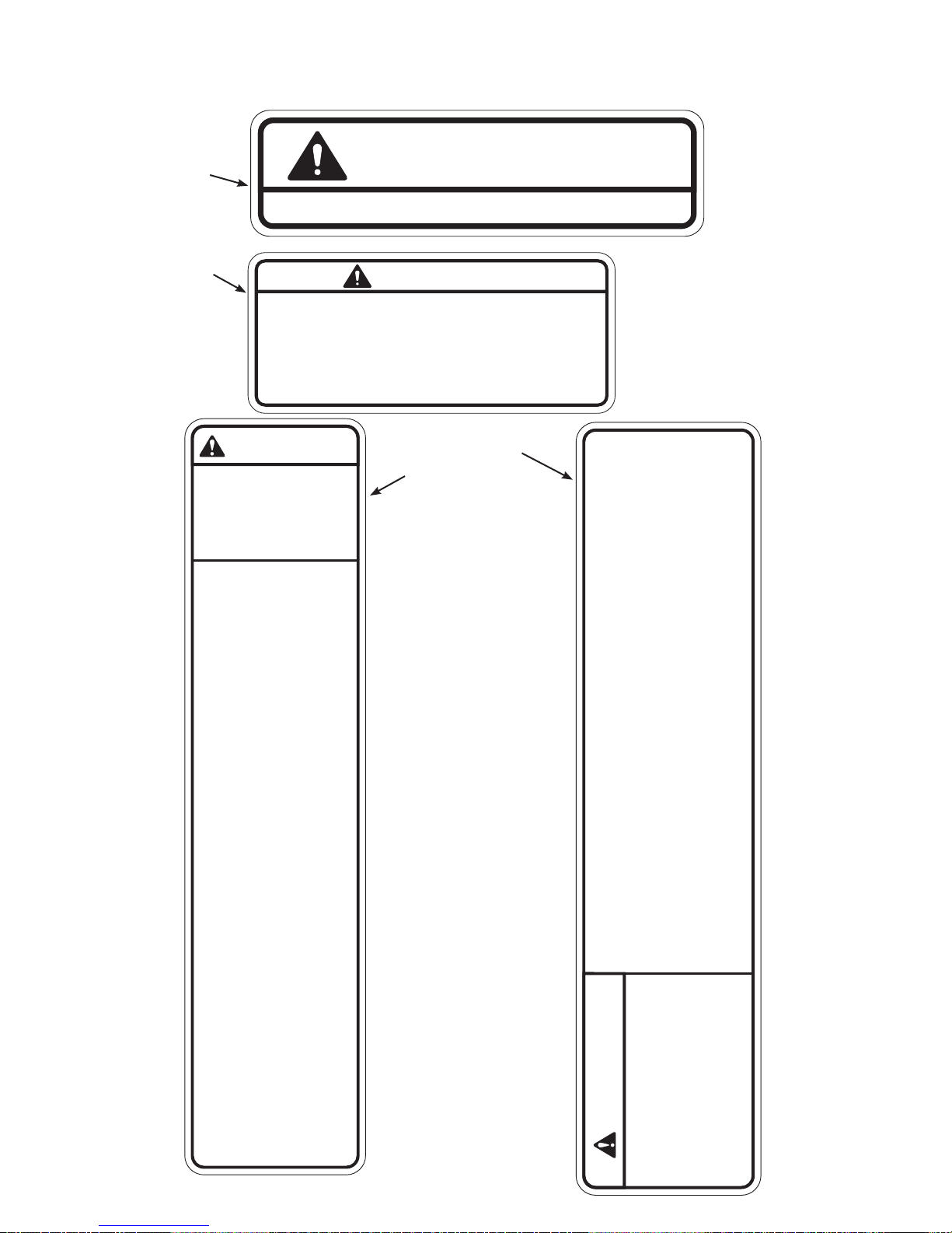
Warning/Caution Decals
Warning decals indicate a potentially hazardous situation, which, if not avoided, could result in death
or serious injury.
Caution decals indicate a potentially hazardous situation, which, if not avoided, could result in minor
or moderate injury.
The caution and warning decals are shown on the following page. The diagrams following the decals
show where each decal is located.
Safety
Page 1-2
Page 9
Cybex Free Weight Owner’s Manual
A
To avoid injury, do not adjust angle while on unit.
D
Back cushion may drop when knob is pulled. Support
back cushion while adjusting.
Be sure detent pin is fully engaged before use. Return
back cushion to lowest position when not in use.
Failure to do so could result in personal injury.
WARNING
SERIOUS INJURY
COULD OCCUR IF
THESE PRECAUTIONS
ARE NOT OBSERVED
1. Obtain a medical exam prior to
beginning an exercise program.
2. Read and understand warning
labels and user manual prior to
exercising. Obtain instruction prior
to use.
3. Keep body and clothing free from
and clear of all moving parts.
4. Inspect machine prior to use. DO
NOT use if it appears damaged or
inoperable.
CAUTION
CM000219 C
CAUTION
8500-028 B
C
B
11. Inspect all cables and belts and
connections prior to use. DO NOT
use if any components are worn,
frayed, or damaged.
12. Children must not be allowed near
this machine.Teenagers must be
supervised.
5220-365 D
13. DO NOT REMOVE THIS LABEL.
REPLACE IF DAMAGED.
14. Stop exercising if you feel faint,
dizzy or experience pain at any
time will exercising and consult
your physcian.
5. DO NOT attempt to fix a broken
or jammed machine. Notify floor
staff.
6. Use the machine only for the
intended use. DO NOT modify the
machine.
7. Load plates evenly and carefully
to avoid tipping equipment and
crushing injuries.
8. Use a spotter.
9. DO NOT use if guards are
missing or damaged.
10. DO NOT use dumbbells or
other incremental weights, except
those provided by the manufacturer.
11. Inspect all cables and belts and
connections prior to use. DO NOT
use if any components are worn,
frayed, or damaged.
12. Children must not be allowed
near this machine.Teenagers must
be supervised.
13. DO NOT REMOVE THIS
LABEL. REPLACE IF DAMAGED.
5220-364 C
7. Load plates evenly and carefully to
avoid tipping equipment and
intended use. DO NOT modify the
machine.
beginning an exercise program.
2. Read and understand warning
labels and user manual prior to
exercising. Obtain instruction
crushing injuries.
8. Use a spotter.
3. Keep body and clothing free from
prior to use.
6. Use the machine only for the
1. Obtain a medical exam prior to
WARNING
SERIOUS INJURY
COULD OCCUR IF
9. DO NOT use if guards are missing
or damaged.
10. DO NOT use dumbbells or other
incremental weights, except those
provided by the manufacture.
5. DO NOT attempt to fix a broken or
and clear of all moving parts.
4. Inspect machine prior to use. DO
jammed machine. Notify floor staff.
NOT use if it appears damaged
or inoperable.
THESE PRECAUTIONS
ARE NOT OBSERVED
Safety
Page 1-3
Page 10
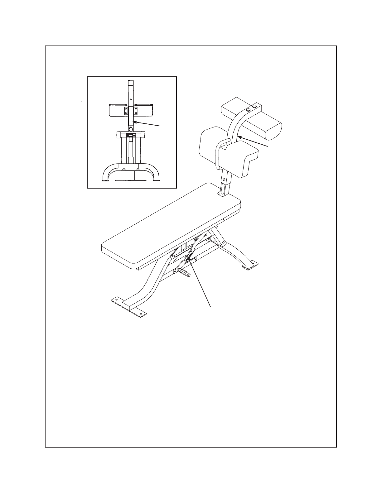
Cybex Free Weight Owner’s Manual
Bent Leg Ab Board - 5208
B
B
DESCRIPTION PART NO.
Safety
Page 1-4
A
Caution Decal....................CM000219-4
A.
Warning Decal...................5220-364-4
B.
Page 11
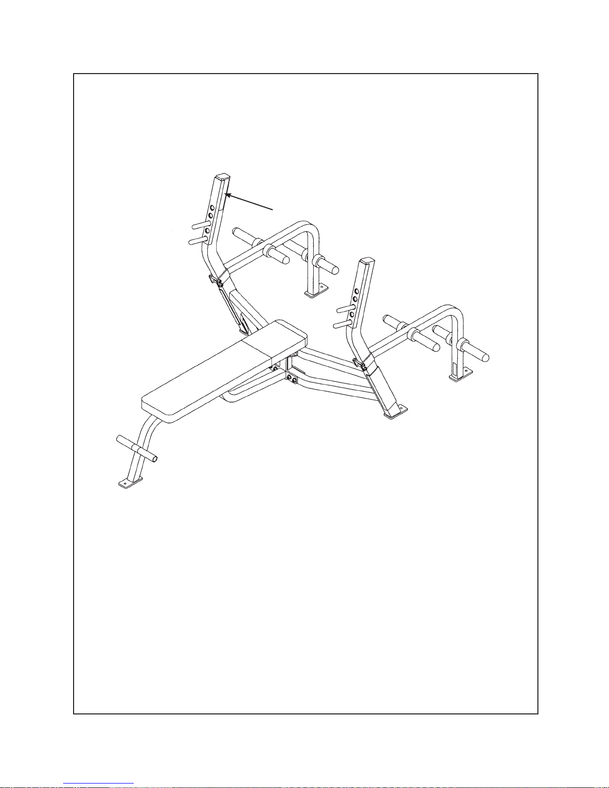
Cybex Free Weight Owner’s Manual
Olympic Bench Press/Weight Storage Attachment - 5362 and 5363
B
DESCRIPTION PART NO.
Warning Decal...................5220-364-4B.
Safety
Page 1-5
Page 12
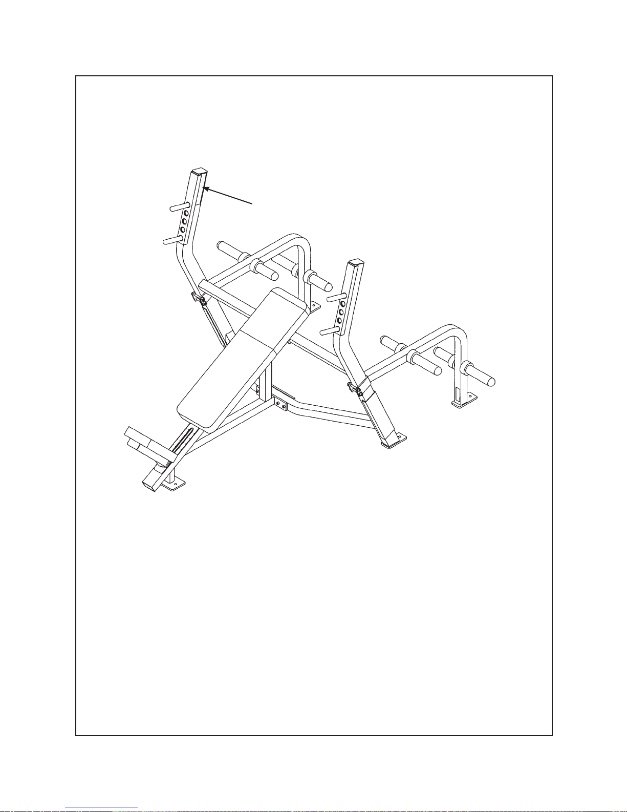
Cybex Free Weight Owner’s Manual
Olympic Incline Bench/Weight Storage Attachment - 5372 and 5363
B
DESCRIPTION PART NO.
Safety
Page 1-6
Warning Decal...................5220-364-4B.
Page 13
Cybex Free Weight Owner’s Manual
45 Degree Back Extension - 5411
B
DESCRIPTION PART NO.
Warning Decal...................5220-364-4B.
Safety
Page 1-7
Page 14
Cybex Free Weight Owner’s Manual
Power Cage and Power Cage Attachment - 5420 and 5425
Safety
Page 1-8
B
DESCRIPTION PART NO.
Warning Decal...................5220-364-4B.
Page 15
Cybex Free Weight Owner’s Manual
Adjustable Bench - 5437
C
DESCRIPTION PART NO.
Caution Decal...................8500-028-4C.
Safety
Page 1-9
Page 16
Cybex Free Weight Owner’s Manual
Adjustable Decline - 5445
B
DESCRIPTION PART NO.
Safety
Page 1-10
Warning Decal...................5220-364-4B.
Page 17
Cybex Free Weight Owner’s Manual
Scott Curl Station - 5460
B
DESCRIPTION PART NO.
Warning Decal...................5220-364-4B.
Safety
Page 1-11
Page 18
Cybex Free Weight Owner’s Manual
Military Press Station - 5471
B
DESCRIPTION PART NO.
Safety
Page 1-12
Warning Decal...................5220-364-4B.
Page 19
Cybex Free Weight Owner’s Manual
Training Station - 5480
B
DESCRIPTION PART NO.
Warning Decal...................5220-364-4B.
Safety
Page 1-13
Page 20
Cybex Free Weight Owner’s Manual
Olympic Decline Bench/Weight Storage Attachment - 5502 and 5363
B
DESCRIPTION PART NO.
Safety
Page 1-14
Warning Decal...................5220-364-4B.
Page 21
Cybex Free Weight Owner’s Manual
Dip/Chin Station - 5510
B
DESCRIPTION PART NO.
Warning Decal...................5220-364-4B.
Safety
Page 1-15
Page 22
Cybex Free Weight Owner’s Manual
Leg Raise Chair - 5530
B
DESCRIPTION PART NO.
Warning Decal...................5220-364-4B.
Safety
Page 1-16
Page 23
Cybex Free Weight Owner’s Manual
Squat Rack With Adjustable Stop - 5570
C
DESCRIPTION PART NO.
Warning Decal...................5220-365-4C.
Safety
Page 1-17
Page 24

Cybex Free Weight Owner’s Manual
Regular Maintenance Activities
Preventative maintenance activities must be performed to maintain normal operation of your Free
Weight equipment. Keeping a log sheet of all maintenance actions will assist you in staying current with
all preventative maintenance activities. The preventative maintenance actions are described in detail in
Chapter 6. Briefl y, they include:
! WARNING: Equipment found to have worn or damaged components must be removed
from service until repair(s) is made. Failure to do so could result in injury.
Daily
1. Clean upholstery.
Weekly
1. Inspect all nuts and bolts for looseness. Tighten as required.
2. Check for worn handles, and worn warning labeling. Replace all worn parts immediately.
As Required
1. Inspect grips and replace as necessary.
Using Proper Form
Before working out, read and understand the training suggestions listed in Chapter 3.
Safety
Page 1-18
Page 25

Cybex Free Weight Owner’s Manual
2 - Technical Specifi cations
General Specifications
Frame Finish
Shall be made of mechanical quality 11 gauge and 16 gauge steel purchased in mill run quantities to
•
assure the best consistency.
Prior to applying fi nish, each part shall be put through a multi-stage wash to remove all oils and to
•
chemically prepare the surface for maximum adhesion. After the wash, the frames shall be dried and
coated with an Electrostatically applied powdercoat fi nish that shall be applied in powder form and
then baked until cured.
The fi nish shall be textured and very hard, assuring a scratch and chip resistant fi nish.
•
Handgrips
Machines shall use a closed-end PVC closed cell foam vinyl sleeve.
•
Diameter should be 1 3/8” to increase comfort through reduced pressure.
•
Frame Construction
Primarily 1 1/2” x 2” tubing with 11 gauge wall thickness, but different tubing sizes and wall thickness
•
shall be used as required through engineering stress analysis.
Fully welded frames for maximum structural integrity and minimum maintenance.
•
Hardware
All 3/8” socket head cap screws shall be of grade 8 (or equivalent). All bolts shall be either chromed
•
or zinc plated for additional corrosion resistance.
Technical
Specifications
Page 2-1
Page 26

Cybex Free Weight Owner’s Manual
Cushion/Upholstery
A superior grade of Boltafl ex or Naugahyde from Omnova shall be used on all pad covers and
•
wear covers.
The color shall be sulfi de stain resistant.
•
All edges shall be stitched to eliminate any folds in the material that would limit durability.
•
Cushions come with replaceable slipcovers on all high use areas, reducing maintenance expense
•
by not having to replace the entire cushion.
Cushion foam consists of a combination of high and medium density closed-cell Omalon poly-
•
urethane, for durability and comfort.
Adjustments
Recessed high contrast Lexan decal for all seat and pad adjustments for maximum readability.
•
Instructional Placard
Used on Bent Leg Abdominal Board, (Product No. 5208).
•
Shall provide step-by-step instructions and a picture to illustrate use.
•
Placard shall indicate proper positioning, and clearly describe the correct use of machines.
•
Equipment Anchoring
Each machine shall be equipped with a provision for anchoring it to the fl oor.
•
Weight Storage
All weight storage pins shall be made of hot-rolled electrically welded steel and bright zinc plated
•
for corrosion resistance and durability.
All weight storage pins shall be fi tted with rubber bumpers to protect frame fi nish and free weight
•
plates.
Wear Guards
Ultra High Molecular Weight (UHMW) extruded plastic u-bumpers shall be affi xed to appropriate
•
machines with double coated foam tape. This will protect the frame fi nish from leaning weight plates.
Dumbbell Saddles
Shall be high density polyethylene plastic and resistant to wear and breakage.
•
Technical
Specifications
Page 2-2
Page 27
Cybex Free Weight Owner’s Manual
Machine Specifications
Squat Rack - Product No. 5570
(Squat Rack With Adjustable Bar Stops - Product No. 5571)
Top View
Isometric View
length
width
width
length
Total Weight Size
289 lbs. inches - 71 W x 70 L x 70 H
131 kg cm - 181 cm W x 178 cm L x 178 cm H
Removable chamfered pins for accurate positioning and convenience.
•
Adjustable bar stops for additional movements and safety.
•
Zinc-coated plate holders and UHMW wear guards to protect paint fi nish from contact with the bar.
•
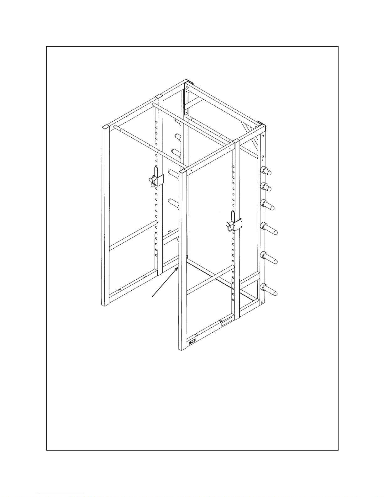
Power Cage - Product No. 5420
Top View
Isometric View
Total Weight Size
379 lbs. inches - 52 W x 52 L x 96 H
172 kg cm - 132 cm W x 132 cm L x 244 cm H
•
Full 36” depth provides ample room to maneuver and 96” height allows full press-outs by tall lifters.
•
Adjustable trigger bar stops and a sturdy lock design for safety.
•
Built-in chin-up bar at 8’ provides exercise variety.
•
Weight Storage adds twelve plate sleeves and a chin-up bar at 6’.
Technical
Specifications
Page 2-3
Page 28

Cybex Free Weight Owner’s Manual
Training Station - Product No. 5480
Top View
Isometric View
Total Weight Size
178 lbs. inches - 48 W x 40 L x 45 H
81 kg cm - 122 cm W x 102 cm L x 115 cm H
Platform has necessary height to clear 45 lb. plates in deadlift exercise.
•
Rugged platform and safety catches in 3” increments provide safety and stability.
•
UHMW wear guards protect the uprights frame fi nish from bar contact.
•
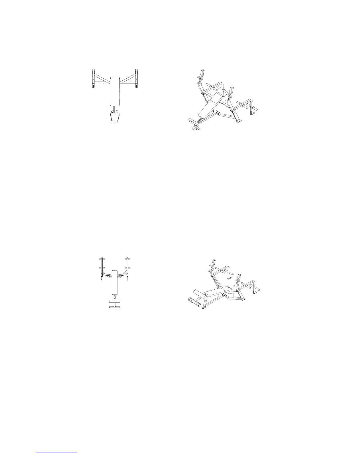
Olympic Bench Press - Product No. 5362
Top View
Isometric View
Total Weight Size
116 lbs. inches - 50 W x 69 L x 49 H
53 kg cm - 127 cm W x 176 cm L x 125 cm H
•
Frame is contoured for easy spotter access and a foot rest provides smaller uses enhanced stability.
•
Removable chamfered weight pins provide adjustability.
•
Optional weight storage attachment is space saving and maintains weight plates in close proximity.
•
UHMW wear guards protect frame fi nish from leaning weight plates.
Technical
Specifications
Page 2-4
Page 29
Cybex Free Weight Owner’s Manual
Olympic Incline Press - Product No. 5372
Top View
Total Weight Size
124 lbs. inches - 50 W x 58 L x 54 H
56 kg cm - 127 cm W x 147 cm L x 138 cm H
Bench angle is 30° to emphasize upper pectorals.
•
Frame is contoured for easy spotter access.
•
Seat adjusts to 6 positions for varying torsos and position fi ne-tuning.
•
Optional weight storage attachment is space saving and maintains weight plates in close proximity.
•
UHMW wear guards protect frame fi nish from leaning weight plates.
•
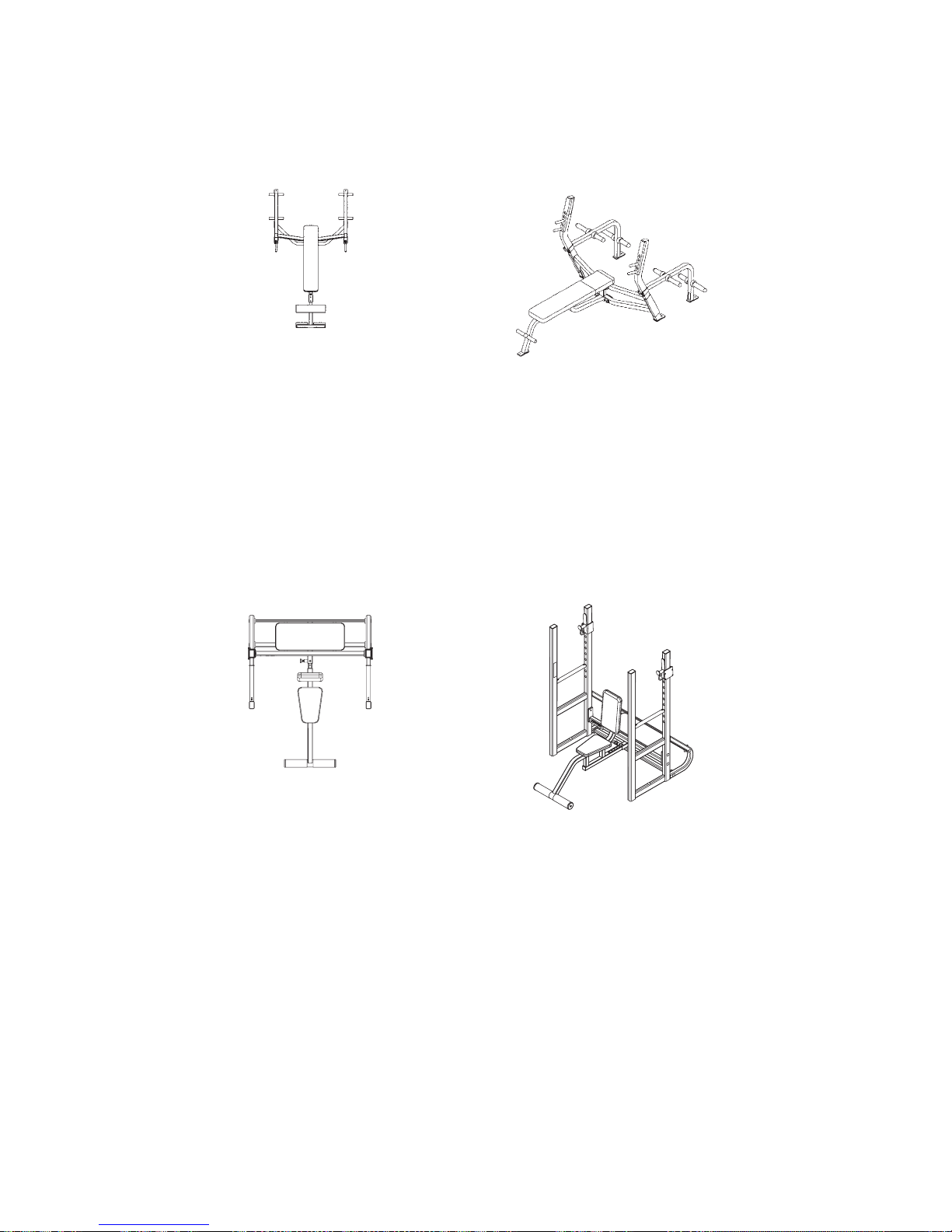
Olympic Decline Press - Product No. 5502
(Olympic Decline Press With Weight Storage Attachment - Product No. 5563)
Isometric View
Top View
Total Weight Size
140 lbs. inches - 50 W x 76 L x 45 H
64 kg cm - 127 cm W x 191 cm L x 115 cm H
Bench angle is 15° to emphasize the lower pectorals.
•
Frame is contoured for easy spotter access.
•
Elevated knee support reduces lower back strain and adjusts to 6 positions for varying torsos
•
and position fi ne-tuning.
•
Optional weight storage attachment is space saving and maintains weight plates in close proximity.
•
UHMW wear guards protect frame fi nish from leaning weight plates.
Isometric View
Technical
Specifications
Page 2-5
Page 30
Cybex Free Weight Owner’s Manual
Weight Storage Attachment - Product No. 5563
Top View
Isometric View
Total Weight Size
15 lbs. inches - 8 W x 15 L x 22 H
7 kg cm - 20 cm W x 40 cm L x 56 cm H
For use with product numbers 5362, 5372 and 5502.•
Military Press - Product No. 5471
Top View
Isometric View
Total Weight Size
223 lbs. inches - 63 W x 50 L x 67 H
101 kg cm - 160 cm W x 127 cm L x 171 cm H
•
Seat is adjustable fore or aft allowing varying take-off positions.
•
Trigger bar stops are adjustable in 3” increments, and a spotter’s platform increases
to the safety profi le.
•
Footrest enhances user stability.
Technical
Specifications
Page 2-6
Page 31

Scott Curl - Product No. 5460
Cybex Free Weight Owner’s Manual
Top View
Isometric View
Total Weight Size
80 lbs. inches - 28 W x 40 L x 38 H
36 kg cm - 72 cm W x 102 cm L x 97 cm H
•
Elbow pad is angled 55° for varying resistance and comfort.
•
Dual take-off pins increase safety.
•
Seat adjusts for varying torsos and position fi ne-tuning.
•
UHMW wear guards protect the uprights frame fi nish from bar contact.
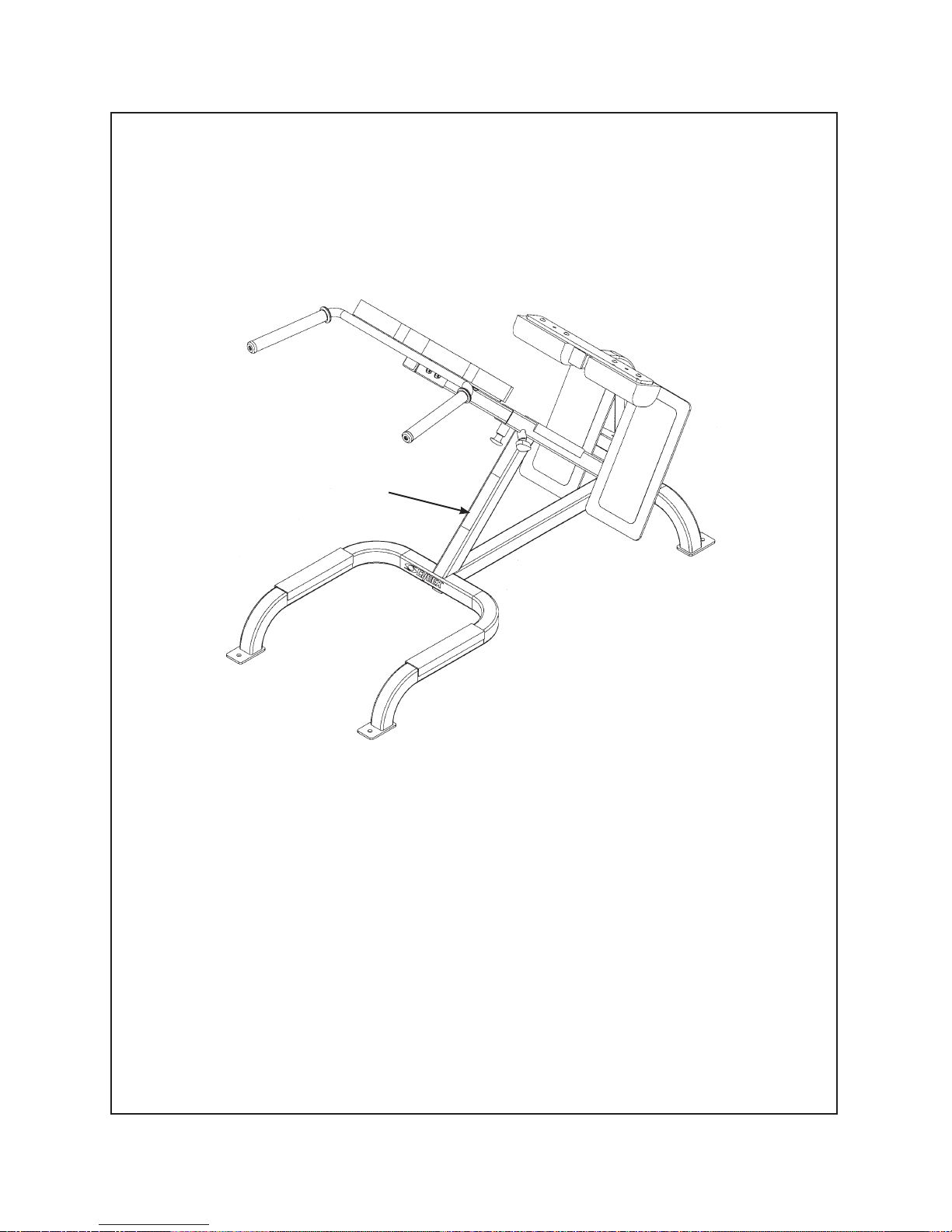
Bent Leg Abdominal Board - Product No. 5208
Top View
Isometric View
Total Weight Size
128 lbs. inches - 24 W x 59 L x 45 H
58 kg cm - 61 cm W x 150 cm L x 115 cm H
Foot release adjusts back pad in fi ve increments from -30° to 10°.
•
Leg pad reduces lower back strain and adjusts for femur length.
•
Handgrip allows for easy ingress/egress.
•
Technical
Specifications
Page 2-7
Page 32

Cybex Free Weight Owner’s Manual
45° Back Extension - Product No. 5411
Top View
Isometric View
Total Weight Size
117 lbs. inches - 27 W x 58 L x 43 H
53 kg cm - 69 cm W x 147 cm L x 109 cm H
Unique footrest to thigh pad angle providing additional relief for the knee joint enhancing
•
both comfort and safety.
•
Start position of 45° provides closer alignment of strength curve for the low back and hamstrings.
•
Adjustment range of 13.5” accommodates users of all sizes.
•
Sturdy design allows dips to be done safely on handles.
•
UHMW wear guards protect frame fi nish from leaning weight plates.
Chin-Up/Dip - Product No. 5510
Top View
Isometric View
Total Weight Size
171 lbs. inches - 46 W x 47 L x 98 H
78 kg cm - 117 cm W x 119 cm L x 249 cm H
Height greater than 8’ allows taller users to perform chin-ups without bending knees while
•
built-in steps provide assistance for smaller users.
•
Angled grips allow a more comfortable hand-wrist position.
•
Choice of grips include a neutral position for individual preference and anatomical limitation.
•
Converging dip-bars allow users of varying shoulder widths greater comfort.
Technical
Specifications
Page 2-8
Page 33

Cybex Free Weight Owner’s Manual
Leg Raise/Dip - Product No. 5530
Top View
Isometric View
Total Weight Size
126 lbs. inches - 30 W x 48 L x 64 H
57 kg cm - 77 cm W x 122 cm L x 163 cm H
Slightly reclined position and angled elbow rests provide a more secure upright positioning.
•
Step-up provides for easy ingress/egress.
•
Sturdy design allows dips to be done safely on dip handles.
•
Twin Tier Dumbbell Rack - Product No. 5380
Top View
Isometric View
Total Weight Size
160 lbs. inches - 89 W x 22 L x 31 H
73 kg cm - 226 cm W x 56 cm L x 79 cm H
•
Offset angle prevents wrist strain while removing and replacing dumbbells.
•
Individual dumbbell cradles improves rack safety profi le.
•
Storage space for 10 pairs of any size dumbbell.
•
Dumbbell saddles made of wear resistant high-density polyethylene plastic.
Technical
Specifications
Page 2-9
Page 34

Cybex Free Weight Owner’s Manual
Single Tier Dumbbell Rack - Product No. 5385
Top View
Isometric View
Total Weight Size
123 lbs. inches - 89 W x 22 L x 31 H
56 kg cm - 226 cm W x 56 cm L x 79 cm H
•
Offset angle prevents wrist strain while removing and replacing dumbbells.
•
Individual dumbbell cradles improves rack safety profi le.
•
Storage space for 5 pairs of any size dumbbell.
•
Dumbbell saddles made of wear resistant high-density polyethylene plastic.
Beauty Bell Rack - Product No. 5375
Top View
Isometric View
Total Weight Size
82 lbs. inches - 43 W x 23 L x 31 H
37 kg cm - 110 cm W x 59 cm L x 79 cm H
Designed specifi cally for beauty bell set (#51022).
•
Holds six pairs of dumbbells.
•
Dumbbell saddles made of wear resistant high-density polyethylene plastic.
•
Technical
Specifications
Page 2-10
Page 35

Barbell Rack - Product No. 5541
Cybex Free Weight Owner’s Manual
Top View
Total Weight Size
105 lbs. inches - 32 W x 38 L x 55 H
48 kg cm - 82 cm W x 97 cm L x 140 cm H
Upright design provides convenience for barbell access.
•
Rack holds 10 barbells, fi ve per side.
•
UHMW wear guards protect the uprights frame fi nish from bar contact.
•
Flat Bench - Product No. 5430
Isometric View
Top View
Total Weight Size
40 lbs. inches - 20 W x 43 L x 17.5 H
18 kg cm - 51 cm W x 109 cm L x 44 cm H
Bench has 3 point contact for improved leveling.
•
Supports user to allow unencumbered foot positioning.
•
Strong but lightweight design can be easily moved.
•
Isometric View
Technical
Specifications
Page 2-11
Page 36

Cybex Free Weight Owner’s Manual
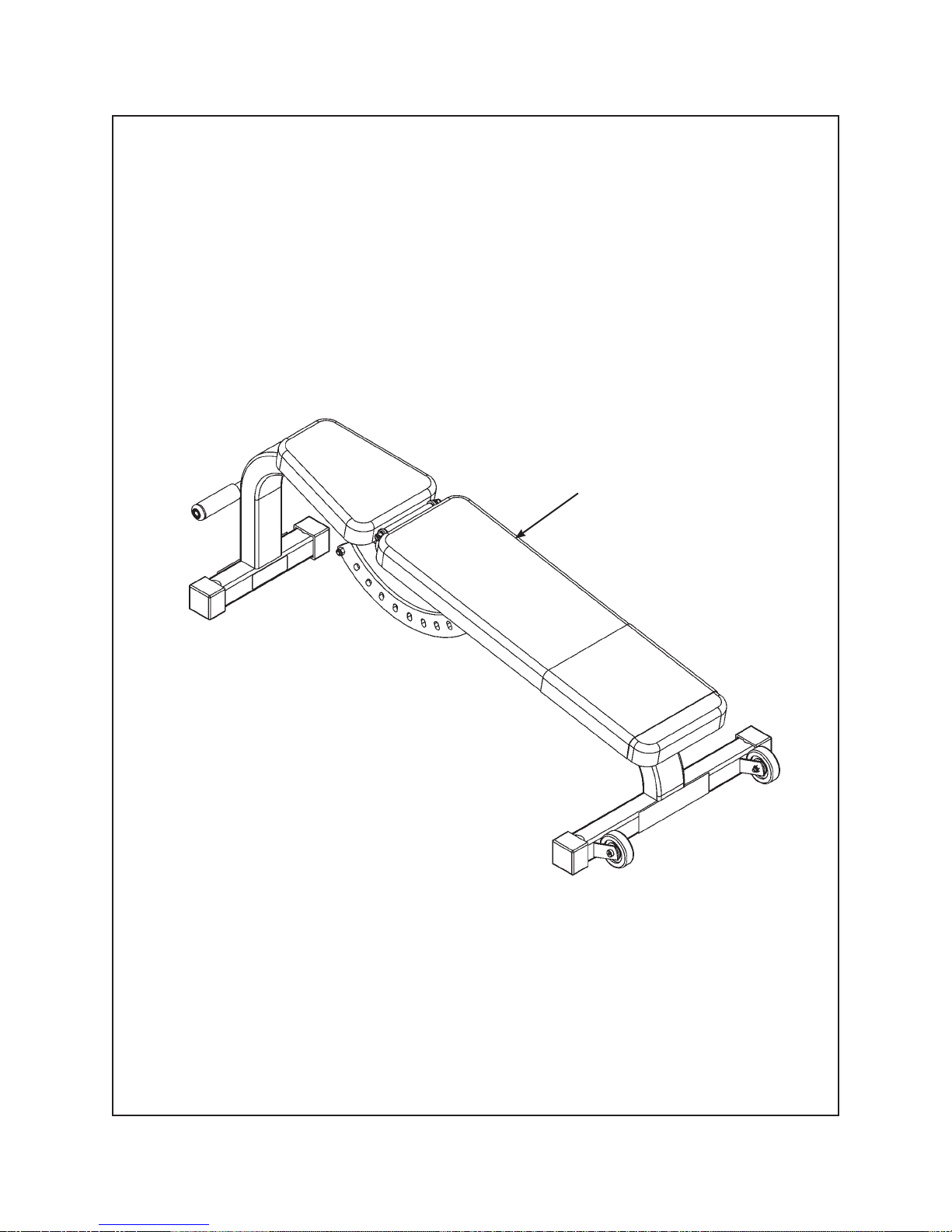
Adjustable Bench - Product No. 5437
Top View
Isometric View
Total Weight Size
80 lbs. inches - 22 W x 52 L x 17 H
36 kg cm - 56 cm W x 132 cm L x 43 cm H
•
Space saving design allows user and facility to have a fl at bench and an incline bench
in one product.
•
Ten seat back positions from -10 to 80°.
•
Features include wheels and a handle for easy moving.
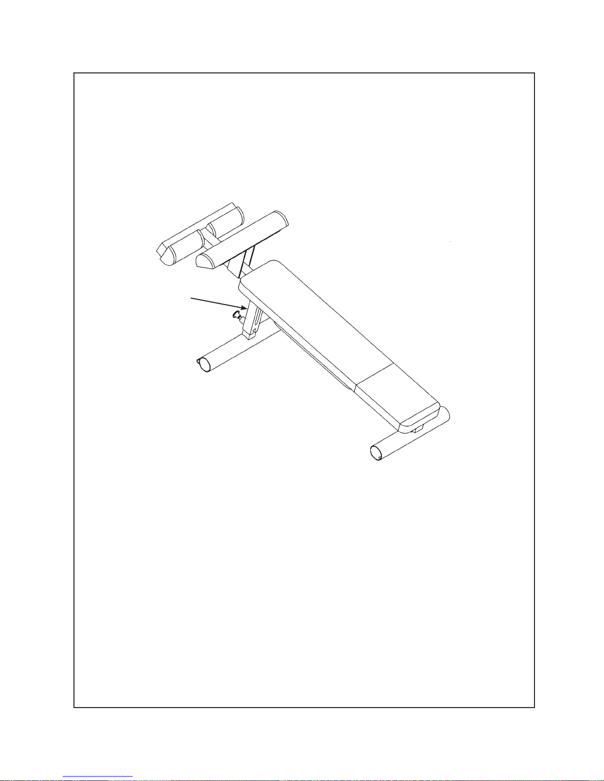
Adjustable Decline Bench - Product No. 5445
Top View
Total Weight Size
66 lbs. inches - 23 W x 61 L x 33 H
30 kg cm - 155 cm W x 94 cm L x 84 cm H
Back pad adjusts from -15° to -30°.
•
Eight distinct reproducible positions.
•
Legs are supported and knees elevated to reduce lower back strain.
•
Isometric View
Technical
Specifications
Page 2-12
Page 37

Cybex Free Weight Owner’s Manual
Upright Bench - Product No. 5521
Top View
Isometric View
Total Weight Size
40 lbs. inches - 28 W x 47 L x 38 H
18 kg cm - 71 cm W x 119 cm L x 97 cm H
Back angle is 85° which improves comfort and stability without interfering with overhead movements.
•
Footrest increases stability.
•
Weight Bar Tree - Product No. 5490
Top View
Isometric View
Total Weight Size
63 lbs. inches - 26 W x 28 L x 46 H
29 kg cm - 66 cm W x 71 cm L x 117 cm H
•
Six zinc-coated storage pegs for Olympic plates, 1000 lbs. capacity.
•
Stores two Olympic bars vertically for maximum space effi ciency.
•
Rubber bumpers on storage pegs protect frame fi nish from plates.
•
Hemispherical rubber end caps on pegs assist loading and dampen noise.
Technical
Specifications
Page 2-13
Page 38

Weight Tree - Product No. 5491
Cybex Free Weight Owner’s Manual
Top View
Isometric View
Total Weight Size
52 lbs. inches - 24 W x 29 L x 45 H
24 kg cm - 74 cm W x 64 cm L x 110 cm H
Six zinc-coated storage pegs for Olympic plates, 1000 lbs. capacity.
•
Rubber bumpers on storage pegs protect frame fi nish from plates.
•
Hemispherical rubber end caps on pegs assist loading and dampen noise.
•
Technical
Specifications
Page 2-14
Page 39

Cybex Free Weight Owner’s Manual
3 - General Exercise Guidelines
Training Suggestions
Before you workout
Prior to starting a training program, get a complete physical exam to make sure your physician agrees
that you are ready. Always warm-up your muscles before a workout. A 5 - 10 minute cardio warm-up
followed by slow stretching (no bouncing) is recommended. Continue with a lighter set (50% of normal of
intended exercises. Proper breathing is very important. Exhale during muscle exertion, and inhale while
returning to the start position. Start your program conservatively. Choose weights you can easily lift in the
fi rst weeks. Always perform the full range of motion unless you have an injury, then consult a professional
trainer. Your Cybex dealer can help you fi nd one. Know the terms? A “repetition” (rep) is defi ned as one
complete movement through an exercise, returning to the start position. A “set” is a continuous series of
reps usually between 6 - 15.
During your workout
The number of reps. you perform in a set depends on your goal. To build muscle and strength, do fewer
reps (6 - 8) with heavier weight. To fi rm your muscles and build endurance, do more reps. (12 - 15)
with lighter weight. Never “cheat” by shortening the range of motion, bouncing the weight, or shifting
your posture. This may allow you to lift more weight, but it is dangerous and less effective. Catch your
breath between sets, then continue. When “circuit training” move briskly to the next exercise; when
doing multiple sets on one exercise, rest 45 - 90 seconds before the next set. Work up to three sets per
exercise. When you can perform the desired reps and sets for any exercise, increase the weight by a
half or full plate.
Designing your workout
Circuit training is a good way to start. This involves doing one set per exercise, then moving to the next
exercise, pausing only briefl y between them (to keep your heart and breath rate up) until completing a
balanced “circuit” of 8 - 10 exercises for your entire body. Then repeat the circuit. After several weeks,
you can move into multiple sets (3 in a row) per exercise if you choose. For both of these, exercise the
complete body every other day, up to three times a week. Note: A full day’s rest, plus proper nutrition and
hydration are required for optimum muscle-building or toning. Alternatively, work out half your body one
day (e.g., the upper body) and the other half the following day (e.g. the lower body). To reduce muscle
soreness, end each series of sets for a given muscle with a set of increased reps and lighter weights.
At the end of your workout, cool down in a similar way to your warm-up.
General
Exercise
Guidelines
Page 3-1
Page 40

Cybex Free Weight Owner’s Manual
Glossary
Abduction - movement away from the mid-line of the body.
Acceleration - the rate at which an object’s velocity changes with time; that is the change of velocity
divided by the time interval.
Accuracy - freedom from error. Degree of conformity of a measure to a standard or a true value.
Action Line - the direction of pull created by the fi bers or tendons of the muscle at the point of
application.
Active Insuffi ciency - a two joint muscle loses the ability to cross-bridge (generate force) due to full
shortening over its greatest anatomical length and tension created in an opposing muscle (antagonist).
Active Range of Motion - the degree of motion that occurs between two adjacent segments through
voluntary contraction of the agonist.
Active Stabilization - provided by an internal force. Static stabilization is provided through an isometric
contraction where dynamic stabilization is a series of motions. Dynamic stabilizers maintain the relative
positions of the segments, preventing undesirable or unnecessary motions due to external forces as well
as artifacts of internal forces. May also refer to the concentric/eccentric contractions of a muscle acting in
a force couple to produce motion while maintaining a relatively fi xed axis of rotation.
Adipose tissue - fat tissue.
Adduction - movement towards the mid-line of the body.
Agonist - (prime mover) the muscle most involved in producing a movement.
Aerobic - utilizing oxygen.
Aerobic endurance - the ability to persist in physical activities that rely heavily upon oxygen for energy
production.
Anabolic - pertaining to the synthesis of complex substances from simpler substances, especially to the
synthesis of body proteins from amino acids.
Anaerobic - without oxygen.
Anaerobic endurance - the ability to persist in physical activities of short duration that require high
rates of energy expenditure. These high rates of energy expenditure cannot be met solely by aerobic
metabolism.
Anthropometrics - measurements and relationships of length and girth of body parts.
Antagonist - the muscle in opposition to the agonist.
Anatomical Position - standing erect, with feet and palms facing forward.
Anatomical Pulley - a bone or skeletal prominence that alters the direction of the pull of a muscle to
increase the muscle’s mechanical advantage.
General
Exercise
Guidelines
Page 3-2
Page 41

Cybex Free Weight Owner’s Manual
Anatomy - geography, naming by orientation and/or apparent capability (non-functional).
Anchor Points - the points at which a load enters and exits the body and/or limb.
Anterior - anatomical term meaning towards the front. Same as ventral.
Assistant Mover - a muscle that is less effective at performing a specifi ed motion, but does have a
small degree of mechanical ability to help the prime mover. There are many borderline cases.
Atrophy - reduction in size of cells and tissues.
Axis of Rotation - imaginary line or point which an object rotates.
Bilateral - refers to both sides.
Biolocomotion - a perspective/description of the human body and its mechanics based upon
locomotion. All animals with legs (regardless of numbers) move with the same mechanics. Gravity
is the common denominator.
Biomechanics - analysis of the load placed on a joint by both the muscle and resistance. Anatomy,
Kinesiology, and Physics = Engineering.
Body composition - the component parts of the body - mainly fat and fat-free weight.
Calorie - a unit of work or energy equal to the amount of heat required to raise the temperature of 1 g
of water to 1 degree C.
Cam - a mechanical device used to vary leverage.
Carbohydrate - a chemical compound consisting of carbon, hydrogen and oxygen atoms in specifi ed
arrangements. Carbohydrates are major components of food such as bread, potatoes and rice.
Cardiovascular - pertaining to the heart and blood vessels.
Cartilage - there are several types. Hyaline cartilage is a relatively thin covering on the ends of many
bones. It forms a smooth, resilient, low friction surface for the movement of one bone on another.
Wedges of cartilage (fi brocartilage) called menisci, disks and labrums are to increase stability, provide
shock absorption, and to facilitate motion in some joints.
Center of Gravity - the center of a body’s mass. In the human body, it is the point which all parts are
in balance with one another. The COG may be within the body, altered by the position of the body even
to the point of being outside the body (pike position), or altered by the addiction of load to specifi c body
areas.
Circumduction - a circular movement permitted at ball and socket, condylar and saddle joints. Consists
of fl exion, abduction, extension and adduction in sequence.
Circuit Training - a conditioning program consisting of a number of exercises performed at “stations”.
Usually, a given exercise is performed at a station within a specifi ed time; then the athlete moves to the
next station, with its own particular exercise and specifi ed time, then to the next station, and so on.
General
Exercise
Guidelines
Page 3-3
Page 42

Cybex Free Weight Owner’s Manual
Closed Chain Kinetic Exercise - a series of rigid links interconnected by a series of pincentered joints.
These are constructed so that motion at one joint will produce motion at all the joints in the system.
Produces greater mechanical effi ciency at the risk of increased joint loading. Leg press, bench press.
Close-Packed Position - all synovial joints have a position where joint surfaces are maximally congruent
and the ligaments and capsule are maximally taut.
Collagen - a fi brous protein that serves as the major component of ligaments and tendons.
Compression - two forces acting along the same line towards each other that constitute a compressive
load or compressive stress.
Concentric action - contraction of a muscle resulting in shortening of the muscle.
Connective Tissue - comprised of mostly the proteins collagen and elastin with water; includes tendons,
ligaments, bursae, cartilage, disks, menisci, fascia and bone.
Cross-bridge - the connection and intertwining of the actin and myosin fi laments in a myofi bril relative to
a muscular contraction.
Curvilinear Motion - the frequently occurring combination of rotatory and translatory motions.
Distraction - two forces acting along the same line and in opposite directions, they constitute a
distractive, tensile load or tensile stress.
Diathrodial Joint - ball and socket joint.
Distal - furthest from the attached end of the limb; away from the body.
Dorsal - pertaining to the back; opposite of ventral, palmar or plantar.
Dorsifl exioni - movement of the foot up in the sagitial plane; movement toward the leg.
Eccentric - muscle action in which tension is developed in the muscle while it is lengthening.
Negative work is performed.
Eccentric Action - a muscle contraction incapable of overcoming the resistance imposed;
the overall muscle length increases.
Endurance - the ability to persist in performing some physical activity.
Energy - the capacity to perform work.
Energy (kinetic) - energy associated with motion.
Energy (potential) - energy by virtue of position.
Energy System - one of three metabolic systems involving a series of chemical reactions resulting
in the formation of waste products and the manufacture of ATP.
Eversion - movement of the sole of the foot outward; opposite of inversion.
Extension - movement at a joint, bringing two parts into or towards a straight line, increasing the angle
of the joint. Returning to anatomical position from a position of fl exion in the sagitial plane.
General
Exercise
Guidelines
Page 3-4
Page 43

Cybex Free Weight Owner’s Manual
External Force - a push or pull on the body that arises from a source outside the body.
External Rotation - movement of the anterior surface of a segment away from the mid-line; also
termed lateral rotation.
Fast-twitch Fibers - skeletal muscle fi bers most active in short-duration, intensive exercise, e.g.,
in sprints and jumps.
Fatigue - the inability to maintain a given level of physical performance.
Flexibility - the range of movement of a specifi c joint or group of joints, infl uenced by the associated
bones and bony structures, muscles, tendons and ligaments.
Flexion - movement about a joint in which bones on either side of the joint are brought closer together,
decreasing the angle of the joint. Joint movement away from anatomical position, occurring within the
sagitial plane.
Foot-pound - the work required to move one pound of resistance one foot in distance.
Force - an interaction between two objects, in the form of a push or pull, that may or may not produce
motion, Force = mass x acceleration.
Force Angle - (FA) the angle between the action line and the lever, on the side of the joint axis.
Force Couple - concentric/eccentric contractions of opposing muscles acting to produce motion while
maintaining a relatively fi xed axis of rotation.
Frontal Plane - (coronal) imaginary line that divides the body into anterior and posterior halves;
lies at a right angle to the sagittal plane.
Fulcrum - the support on which a lever rotates in moving or lifting.
Hyperextension - continuation of the movement of extension past the neutral position.
Hypertrophy - increased cell size leading to increased tissue size.
Impulse - the change in momentum.
Inertia - the tendency of a body to remain at rest or continue in motion unless disturbed by an external
force.
Inferior - a lower position upon or within the body.
Insertion - the more distal attachment site of a muscle. The movable part or attachment of a muscle
as opposed to origin.
Intermittent Work - work sessions interrupted by rest sessions.
Internal Forces - act on the body and arise from sources within the human body.
Inversion - moving the sole of the foot inward. Opposite of eversion.
General
Exercise
Guidelines
Page 3-5
Page 44

Cybex Free Weight Owner’s Manual
Isokinetic - action in which the rate of movement is constantly maintained through a specifi c range
of motion even though maximal force is exerted.
Isokinetic Contraction - a muscular contraction through a range of motion at a constant velocity.
Isometric - a contraction in which movement is produced but no movement occurs.
Isometric (static) Contraction - a muscular contraction in which there is no change in the angle of
the involved joint(s) and little or no change in the length of the contracting muscle.
Isotonic - a contraction in which movement is produced.
Medial Rotation - movement around an axis and toward the mid-line of the body. Also termed internal
rotation.
Medial - aspect nearest the mid-line of the body; pertaining to the center. Opposite of lateral.
Metabolism - the sum total of the chemical changes or reactions occurring in the body.
Moment Arm - (MA) the shortest distance between the action line and the joint axis.
Momentum - determined by mass x velocity. Will remain constant unless the object is acted upon
by another force.
Muscle Contraction - shortening of a muscle and/or development of tension in a muscle.
Muscular Endurance - the ability of a muscle or muscle group to perform repeated contractions
against a light load for an extended period of time.
Neutral - a point between the two extremes of a joint’s range of motion.
Obesity - excess body fat.
Open Kinematic Chain - the ends of the limbs are free to move without causing motion at another
joint. Open chain motions are not predictable because the joints amy function either independently or
in unison. Less mechanically effi cient, therefore more stress is placed upon muscular tissue.
Origin - attachment of a muscle that remains relatively fi xed during muscular contraction.
Overload - to exercise a muscle or muscle group against resistance greater than that which is normally
encountered. The resistance (load) can be maximal or near-maximal.
Passive Insuffi ciency - a two-joint muscle loses the ability to cross-bridge (generate force) due to full
lengthening over its greatest anatomical length due to force created in an opposing muscle.
Passive Stabilization - due to noncontractile components. Internal stabilization is created by connective
tissue (muscular support is not provided anatomically or physiologically) and external stabilization is
provided by a bench or brace.
Plane of Motion - a two-dimensional fl at surface running through an object. Motion occurs in the plane
or parallel to the plane.
Plantar - anatomical term referring to the sole or bottom.
General
Exercise
Guidelines
Page 3-6
Page 45

Cybex Free Weight Owner’s Manual
Plantarfl exion - movement of the foot down in the sagittal plane; movement away from the leg.
Posterior - anatomical term meaning toward the back. Opposite of anterior.
Potential Energy - energy by virtue of position.
Power - the product of force and velocity. Work divided by time.
Prime Mover - (agonist) a muscle that is mechanically optimal to produce a specifi c motion at a joint.
There can be more than one prime mover for a particular motion and a specifi c muscle can be a prime
mover for more than one motion at a joint.
Progressive Resistance - overloading a muscle or muscle group consistently throughout the duration
of a weight-resistance program.
Pronation - a triplanar motion at the subtalar joint consisting of abduction, depression and eversion,
resulting in lowering of the longitudinal arch of the foot. Position of the forearm with the palm facing down.
Protein - a basic foodstuff containing amino acids.
Proximal - towards the attached end of the limb or origin.
Range of Motion - the amount of motion available to a joint within the anatomical limits of the joint
structure. Can be classifi ed as Passive (movement produced via a force outside the limb), Active
(movement produced by muscles within the limb) or Resisted (movement challenged under additional
load). The amount of resistance will affect the range of motion with direct proportion.
Reciprocal Inhibition - contraction of agonist causes relaxation of antagonist.
Reliability - the extent to which an experiment, test or measuring procedure yields the same results on
repeated trials. Also known as reproducibility or repeatability.
Repetition Maximum (RM) - the maximum load that a muscle or muscle group can lift in a given number
of repetitions before fatiguing. For example, an eight-RM load is the maximum load that can be lifted
eight times.
Repositioners - muscles that lift the extremity and move it to a new location allowing the prime movers
to again accept load or propel.
Response - a sudden temporary adjustment in physiological function brought on by a single exposure
to exercise, e.g., the rise in heart rate associated with an exercise bout.
Rotary Motion - (radial or angular) the movement of an object around a fi xed axis in a curved path.
S.A.I.D. Principle - Specifi c Adaptation to Imposed Demand. A muscle will gain strength in the specifi c
ranges of motion and speeds in which it is trained.
Sagittal Plane - Imaginary line that divides the body, or any of its parts, into right and left sections.
General
Exercise
Guidelines
Page 3-7
Page 46

Cybex Free Weight Owner’s Manual
Scoliosis - a lateral curvature of the vertebral column, usually in the thoracic area.
Secondary Joint - hinge joints that have a singular function (elbow/knee). Muscles are situated on either
side of these joints in virtual, if not real, pairings.
Set - in an interval training program, a group of work and relief intervals. In weight lifting, the number of
repetitions performed consecutively without resting.
Shear - two parallel forces applied in opposite directions that are not in line with each other constitute
a shearing load or stress. The site of muscular attachment is the axis around which the forces of shear
develop. This becomes the “force axis” as opposed to the anatomical axis.
Shunt Muscle - directs the greater part of its contractile force along the bone it is moving (creating
greater force towards compression/stabilization). The brachioradialis is a shunt during an arm curl.
Skeletal Muscle - muscle controlling skeletal movement that is normally under voluntary control.
Skewing - the result of a vector shift through a limb or system.
Sliding Filament Theory - a muscle shortens or lengthens because the thick and thin myofi brils slide
past one another without the fi laments changing length.
Slow-twitch Fibers - skeletal muscle fi bers characterized by relatively slow contraction times and
great capacity for the aerobic production of adenosine triphosphate.
Sprain - the permanent deformation of the structure due to excessive or prolonged stress/strain.
Spurt Muscle - directs the greater part of its force across the bone it is moving rather than along it
(creating greater effort towards motion). The biceps is a spurt during an arm curl.
Stabilizer - a muscle that steadies or supports a joint in order that another active muscle may have
a fi rm base upon which to pull.
Static contraction - a muscular contraction that does not involve changes in the angle of the joint(s)
involved.
Steady state - that state of physiological stability wherein the energy demands of the body can be
met relatively easily for a prolonged period of time.
Strain - the deformation of the structure as the result of stress.
Strength - the ability to exert muscular force briefl y.
Stress - the force created within a structure when placed under load.
Submaximal exercise - usually exercise at less than maximal intensity, but may also refer to exercise
of less than maximal duration.
Superior - a higher position upon or within the body.
General
Exercise
Guidelines
Page 3-8
Page 47

Cybex Free Weight Owner’s Manual
Synergist - occurs during the action of two muscles, both of which have a common joint action and each
of which has a second action that is antagonistic or opposing to the other. True synergy is simply the
stabilization of one muscle to prevent any action in one of the joints traversed by a multi-joint muscle.
Synovial Fluid - transparent, viscous lubricating fl uid found in joint cavities, bursae and tendon sheaths.
Tendons - cords of dense fi brous tissue that connect muscle to bone.
Tertiary Joint - a complex joint structure (wrist/ankle-subtalor), designed for fi nely controlled movements.
Torque - the ability of a force to produce movement around an axis.
Training - a program of exercise designed to improve the skills and increase the energy capacities of an
athlete for a particular event.
Translatory Motion - (linear) the movement of an object in a straight line.
Unilateral - refers to only one side.
Validity - the extent to which a measurement or information is relevant or meaningful; appropriate to
the end in view and supported by objective truth.
Vector - an arrow which represents a force’s point of application, action line or direction indicating pull
or magnitude of force being exerted.
Vector Shift - the alteration of a load as it is transferred between the anchor points through a segment’s
kinematic chain.
Velocity - the rate at which an objects position changes with time; that is the total change in position
divided by the total change in time: V-d/t.
Weight - the weight of an object is the gravitational force exerted on it by the earth. W=mg, where
g = gravitational acceleration.
Work - W = Fd. The amount of work performed is equivalent to the force applied to an object times the
distance the object is moved.
General
Exercise
Guidelines
Page 3-9
Page 48

Single-Set & Circuit Training Diary
Date
d
Seat
Reps
Plates
Pa
Plates
Reps
MACHINE
Plates
Reps
Plates
Reps
Plates
Reps
Plates
Reps
Plates
Reps
Plates
Reps
Plates
Reps
Plates
Reps
Plates
Reps
Plates
Reps
Page 49

NAME
INSTRUCTOR
Single-Set & Circuit Training Diary
Plates
Date
d
Pa
Seat
MACHINE
Reps
Plates
Reps
Plates
Reps
Plates
Reps
Plates
Reps
Plates
Reps
Plates
Reps
Plates
Reps
Plates
Reps
Plates
Reps
Plates
Reps
Plates
Reps
Page 50

Multiple-Set Training Diary
1 2 3 1 2 3 1 2 3 1 2 3 1 2 3 1 2 3 1 2 3 1 2 3 1 2 3 1 2 3 1 2 3 1 2 3 1 2 3
Date
Seat
Set
Pad
Plates
Reps
Plates
Reps
MACHINE
Plates
Reps
Plates
Reps
Plates
Reps
Plates
Reps
Plates
Reps
Plates
Reps
Plates
Reps
Plates
Reps
Plates
Reps
Plates
Reps
Page 51

NAME
INSTRUCTOR
Multiple-Set Training Diary
1 2 3 1 2 3 1 2 3 1 2 3 1 2 3 1 2 3 1 2 3 1 2 3 1 2 3 1 2 3 1 2 3 1 2 3 1 2 3
Set
Date
Plates
Pad
Seat
MACHINE
Reps
Plates
Reps
Plates
Reps
Plates
Reps
Plates
Reps
Plates
Reps
Plates
Reps
Plates
Reps
Plates
Reps
Plates
Reps
Plates
Reps
Plates
Reps
Page 52

Cybex Free Weight Owner’s Manual
This page intentionally left blank.
General
Exercise
Guidelines
Page 3-14
Page 53

Cybex Free Weight Owner’s Manual
4 - Customer Service
Contacting Service
Hours of phone service are Monday through Friday from 8:00 a.m. to 6:00 p.m. Eastern Standard Time.
For Cybex customers living in the USA, contact Cybex Customer Service at 888-462-9239. Your options
at this number include:
Press 63 to place a parts order or to check parts order status.
•
Press 64 to speak to a technical support representative regarding troubleshooting or to schedule
•
a fi eld service call.
Press 65 to check status of a repair order only and you have your RRM number.
•
Press 66 to check status of a dispatched fi eld service call and you have your inquiry number.
•
Press 67 for service of a medical or isokinetic product.
•
Press 0 to go to the Cybex operator.
•
For Cybex customers living outside the USA, contact Cybex Customer Service at 508-533-4300 or
fax 508-533-5183.
Order parts and fi nd information on the web at www.eCybex.com or by e-mail at techhelp@cybexintl.
com.
Ordering Parts
Visit eCybex.com to shop for parts online or fax your order to 508-533-5183.
To speak with a customer service representative, call 888-462-9239 (for customers living within the USA)
or 508-533-4300 (for customers outside the USA). You may also contact us through email at techhelp@
cybexintl.com
Having the following information ready when calling will assist our Cybex representatives in serving you:
Unit Serial Number
•
Product Name
•
The unit serial number and product name can be found on the serial number decal. See Chapter 7 for
exact location of serial number decal.
Part Description
•
Part Number
•
Part descriptions and part numbers are located in Chapter 7 of this manual.
•
Shipping Address
•
Contact Name
In addition to your shipping address and contact name, your account number is helpful but not required.
Customer
Service
Page 4-1
Page 54

Cybex Free Weight Owner’s Manual
Return Material Authorization (RMA)
The Return Material Authorization (RMA) system outlines the procedures to follow when returning
material for placement, repair, or credit. The system assures that returned materials are properly
handled and analyzed. Follow the following procedures carefully.
Contact your authorized Cybex dealer on all warranty-related matters. Your local Cybex dealer will
request a RMA from Cybex, if applicable. Under no circumstances will defective parts or equipment be
accepted by Cybex without proper RMA and an Automated Return Service (ARS) label.
1. Call the Customer Service Hotline listed above for the return of any time that is defective.
2. Provide the technician with a detailed description of the problem you are having or the defect
in the item you wish to return.
3. Provide the model and serial number of your Eagle equipment
4. At Cybex’s discretion, the technician may request that you return the problem part(s) to Cybex
for evaluation and repair or replacement. The technical will assign you a RMA number and
will send you an ARS label. The ARS label and the RMA numbers must be clearly displayed
on the outside of the package that contains the item(s) to be returned. Include the description
of the problem, the serial number of the Eagle equipment and the name and address of the
owner in the package along with the part(s).
5. Forward the package through UPS to Cybex.
Attn: Customer Service Department
Cybex International, inc.,
1975 24th Ave SW
Owatonna, MN 55060
NOTE: Merchandise returned without an RMA number on the outside of the package or shipments
sent C.O.D. will not be accepted by the Cybex receiving department.
Customer
Service
Page 4-2
Page 55

Cybex Free Weight Owner’s Manual
Damaged Parts
Materials damaged in shipment should not be returned for credit. Shipping damages are the responsibility
of the carrier (UPS, Federal Express, trucking companies, etc.)
Apparent Damage - Upon receipt of your shipment, check all items carefully. Any damage seen with a
visual check must be noted on the freight bill and signed by the carriers agent. Failure to do so will result
in the carriers refusal to honor your damage claim. The carrier will provide you with the required forms for
fi ling such claims.
Concealed Damage - Damage not seen with a visual check upon receipt of a shipment but notices later
must be reported to the carrier as soon as possible. Upon discovery of the damage, a written or phone
request to the carrier asking them to perform an inspection of the materials must be made within ten days
of the delivery date. Keep all shipping containers and packing materials as they will be needed in the
inspection process. The carrier will provide you with and inspection report and the necessary forms for
fi ling a concealed damage claim. Concealed damage claim is the carriers responsibility.
Customer
Service
Page 4-3
Page 56

Cybex Free Weight Owner’s Manual
This page intentionally left blank.
Customer
Service
Page 4-4
Page 57

Cybex Free Weight Owner’s Manual
5 - Assembly
Anchoring
Securely anchor each machine to the fl oor using the anchor holes provided in each machine.
•
NOTE: Cybex is not responsible for the actual anchoring of equipment. Consult with a
professional contractor.
NOTE: Use fasteners having a minimum of 500 lbs. tensile capacity (3/8” grade 2 bolts
or better).
NOTE: If legs/frame does not contact surface, DO NOT pull down with anchors. Shim any
leg or frame not in contact with surface using fl at washers.
Make sure that each machine is set up and operated on a solid level surface. Do not install
•
equipment on an uneven surface.
Assembly
Page 5-1
Page 58

Cybex Free Weight Owner’s Manual
This page intentionally left blank.
Assembly
Page 5-2
Page 59

Cybex Free Weight Owner’s Manual
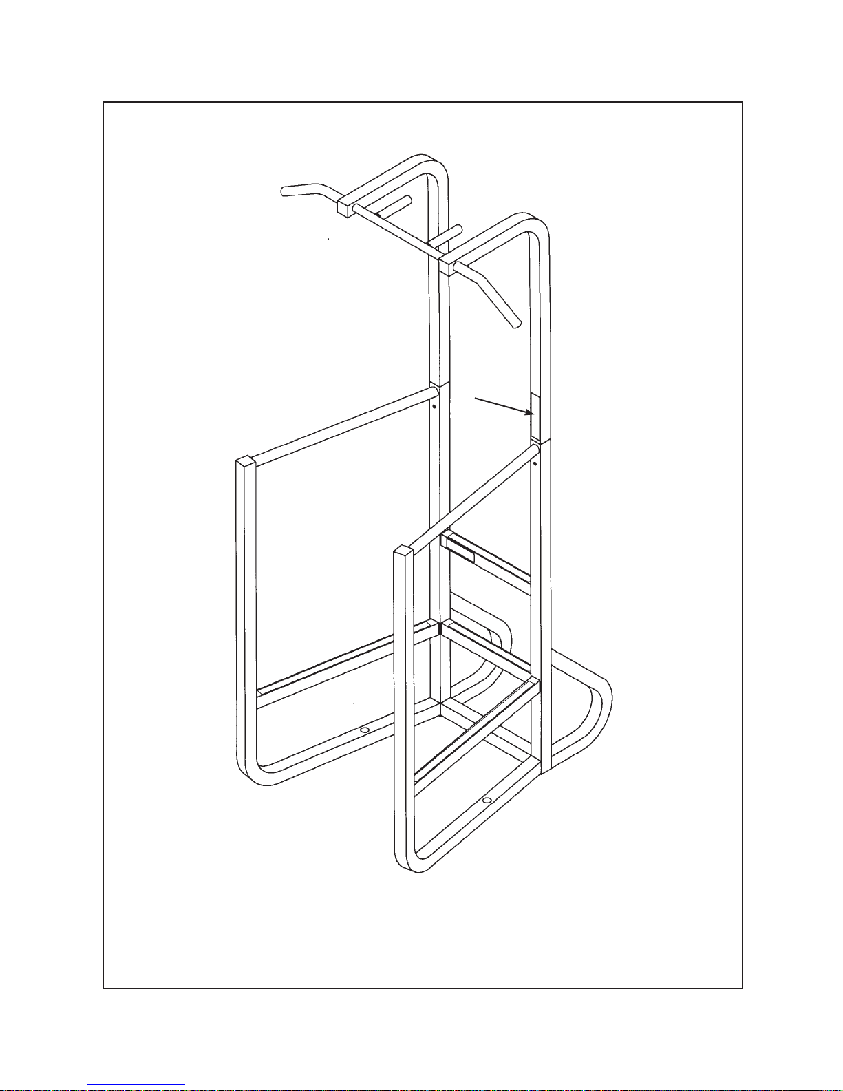
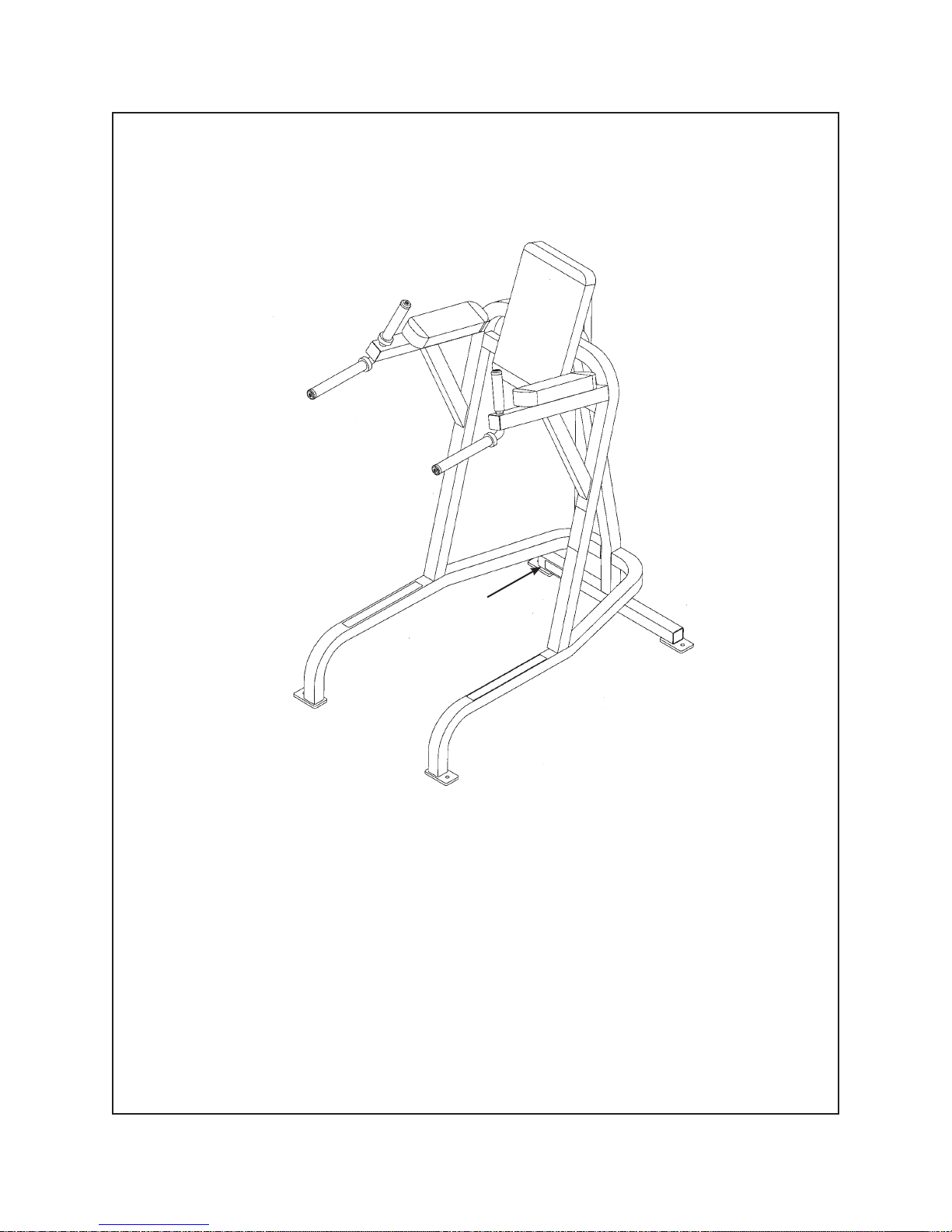
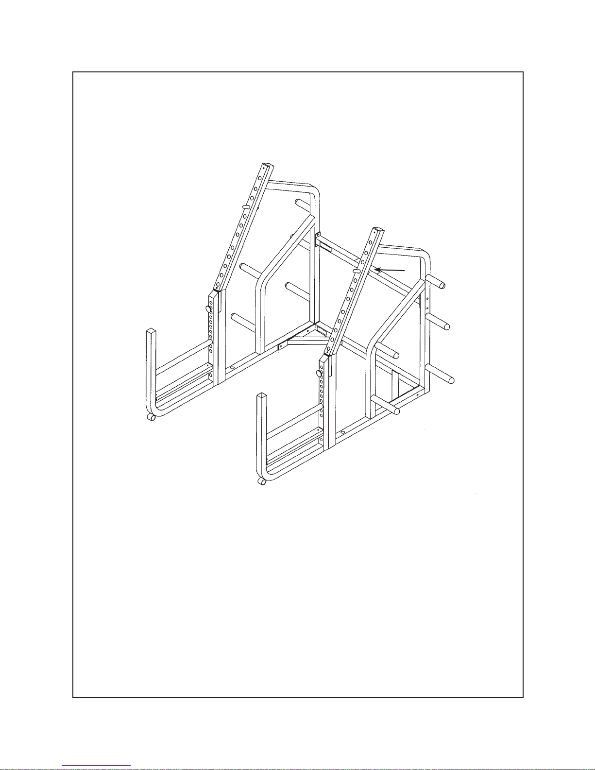
Power Cage and Power Cage Attachment
Assembly
Page 5-3
Page 60

Cybex Free Weight Owner’s Manual
Tools Required
5/16” Allen wrench
•
3/4” wrench
•
3/8” Allen wrench
•
Unpacking Power Cage and Power Cage Attachment Assembly
NOTE: T wo or three people are required to assemble the Power Cage and Power Cage Attachment.
1. Read and understand all instructions thoroughly before assembling the Power Cage and
Power Cage Attachment.
NOTE: Each step number in the assembly instructions tells you what you will be doing. The lettered
steps following each step number describes the procedure required. Do not continue with step 2
until you have carefully read all of the assembly instructions.
2. Verify you have received the appropriate shipping packages.
Verify you received the following: Power Cage Package - 5420-026, Right Side Subassembly -
A.
5420-024-9x, Left Side Subassembly - 5420-025-9x, Attachment Subassembly - 5425A001-9x.
3. Unpacking
Carefully place Power Cage and Power Cage Attachment near area of installation.
A.
Verify contents. See Figures 1 - 4.
B.
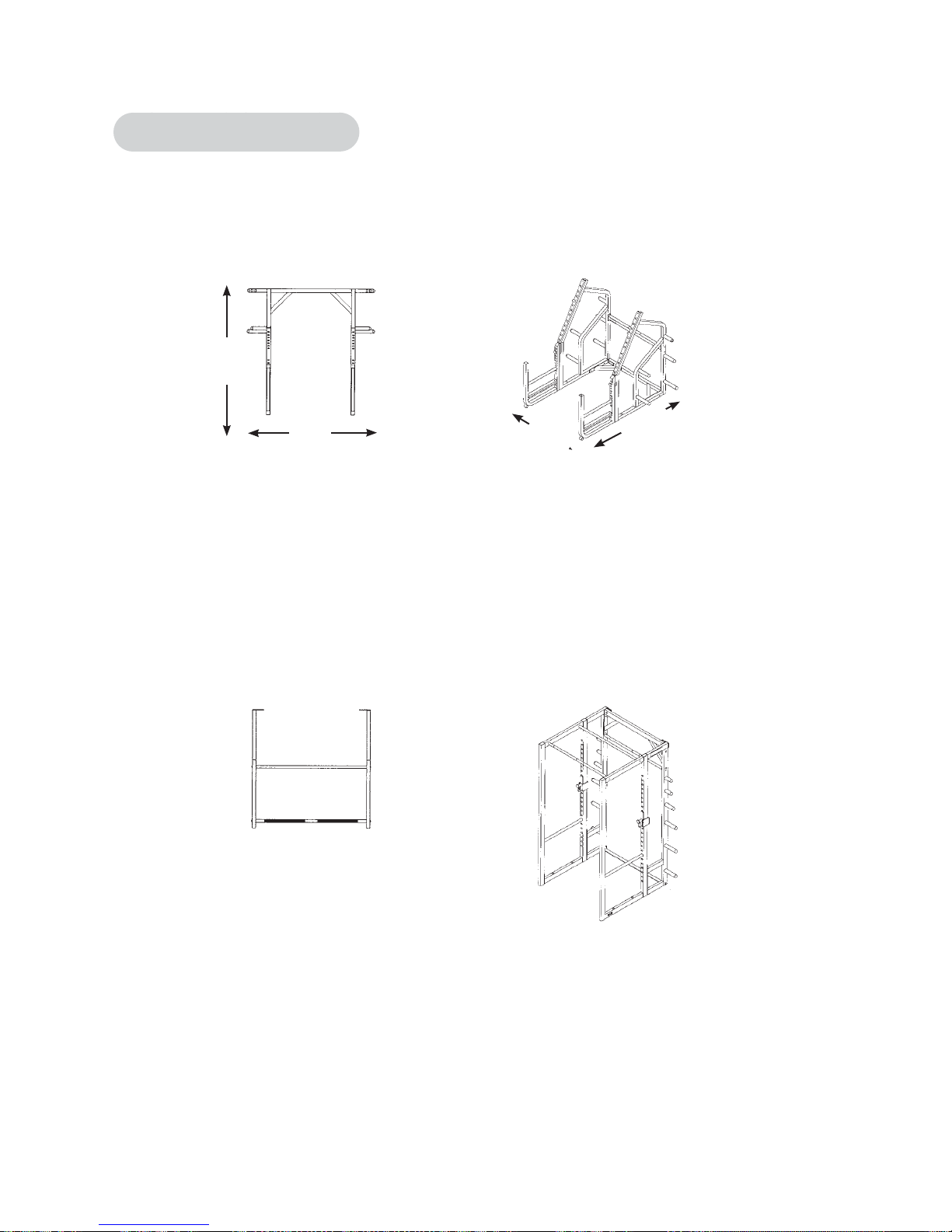
NOTE: If ceiling height is less than 9 feet then Power Cage must be assembled in vertical
(standing) position.
Assembly
Page 5-4
Page 61

Cybex Free Weight Owner’s Manual
ITEM QTY PART NO. DESCRIPTION
10 1 5420-024-98 Right Side
11 1 5420-025-98 Left Side
Figure 1
Assembly
Page 5-5
Page 62

Cybex Free Weight Owner’s Manual
ITEM QTY PART NO. DESCRIPTION
1 1 5420C012 Knurled Support Bar
2 1 5420C013 Smooth Support Bar
3 2 5420-027 Adjusting Bar
4 4 HS387700 Washer SAE .50
5 4 JC780417 BHSCS .50-13 x 1.00
6 4 PP080202 Plastic Insert 1.19 Dia.
7 4 PP080208 Plastic Insert
8 1 5420-002 Right Hand Lock Assembly
9 1 5420-003 Left Hand Lock Assembly
28 1 55420 Assembly Instructions
Figure 2
Assembly
Page 5-6
(not shown)
Page 63

Cybex Free Weight Owner’s Manual
ITEM QTY PART NO. DESCRIPTION
1 1 5420C012 Knurled Support Bar
13 1 5425C013 Bottom Support Bar
19 1 5425W002 Left Side Attachment
20 1 5425W007 Right Side Attachment
21 1 5425W008 Center Brace
Figure 3
Assembly
Page 5-7
Page 64

Cybex Free Weight Owner’s Manual
Figure 4
Assembly
Page 5-8
ITEM QTY PART NO. DESCRIPTION
4 2 HS387700 Washer SAE .50
5 2 JC780417 BHSCS .50-13 x 1.00
6 6 PP080202 Plastic Insert 1.19 Dia.
14 2 5330C042 Spacer Plate
15 12 HN784000 Hex Nut .50-13
16 10 JC782817 SHCS .50-13 x 1.00
17 2 JC782824 SHCS .50-13 x 1.75
18 12 JS388300 Lockwasher .50
28 1 55420 Assembly Instructions
(not shown)
Page 65

Cybex Free Weight Owner’s Manual
4. Install upper support bars (see steps 4A - 4E and Figures 5 and 6).
Locate one knurled support bar (#1), one smooth support bar (#2), four washers .50 (#4) and
A.
four BHSCS .50-13 x 1.00 (#5).
Attach one end of the smooth support bar (#2) to one of the sides (#10 or #11), as shown in
B.
Figure 5 using one washer .50 (#4) and one BHSCS .50-13 x 1.00 (#5). Do not tighten hardware
at this time.
Attach one end of the knurled support bar (#1) to the same side as Step 4B using one
C.
washer .50 (#4) and one BHSCS .50-13 x 1.00 (#5).
Repeat Steps 4B and 4C to attach other side. See Figure 6.
D.
Securely tighten all hardware.
E.
NOTE: Install smooth support bar
5
nearest attachment or wall.
2
4
4
5
11
1
4
5
10
Figure 5
Figure 6
5. Attach lock assembly (see steps 5A and 5B).
Locate right hand lock assembly (#8), left hand lock assembly (#9) and Bar Rack
A.
Accessory Instruction Sheet (#28).
4
2
1
10
B.
Follow instruction sheet (#28) for attaching lock assembly.
Assembly
Page 5-9
Page 66

Cybex Free Weight Owner’s Manual
6. Attach adjusting bars (see steps 6A and 6C and Figure 7).
Locate both adjusting bars (#3).
A.
Position adjusting bar (#3) in Power Cage and align holes. See Figure 7.
B.
Repeat Step 6B to attach other side.
C.
Power
Cage
3
3
Figure 7
7. Secure Power Cage to attachment (see steps 7A - 7K and Figures 8 - 11).
Locate right side attachment (#20), one center brace (#21), one bottom support bar (#13),
A.
four plastic inserts 1.19 Dia. (#6), two spacer plates (#14), two BHSCS .50-13 x 1.00 (#5),
two washers .50 (#4), eight lockwashers .50 (#18), six SHCS .50-13 x 1.00 (#16) and eight
hex nuts .50-13 (#15)
Position right side attachment (#20) up to Power Cage. Align the two holes.
B.
Attach right side attachment (#20) to Power Cage with two SHCS .50-13 x 1.00, two lockwashers
C.
.50 and two hex nuts .50-13. Do not tighten hardware at this time. See Figure 8.
Assembly
Page 5-10
Page 67

Cybex Free Weight Owner’s Manual
20
Power
Cage
16
18
15
18
Figure 8
Position center brace (#21) as shown in Figure 9.
E.
Attach center brace (#21) to Power Cage using two SHCS .50-13 x 1.00 (#16) and two plastic
F.
inserts (#6) two hex nuts .50-13 (#15) and two lock washers .50 (#18). Do not tighten hardware
at this time. See Figure 9.
Power
21
Cage
15
18
15
18
16
6
16
Figure 9
Assembly
Page 5-11
Page 68

Cybex Free Weight Owner’s Manual
Position spacer plate (#14) between center brace (#21) and Power Cage.
G.
Secure spacer plate (#14) to Power Cage and center brace (#21) using one hex nut .50-13, one
H.
lockwasher .50 (#15), one SHCS .50-13 x 1.75 (#18) and one plastic insert 1.19 Dia. (#6). See
Figure 10.
Power
Cage
15
18
14
14
21
6
17
17
15
18
6
Figure 10
Position knurled support bar (#1) between right and left side attachments (#19 and #20) under
I.
center brace (#21).
Secure knurled support bar (#1) using two washers .50 (#4) and two BHSCS .50-13 x 1.00 (#5).
J.
See Figure 11.
K.
Repeat Steps 7H and 7J for other side.
19
Figure 11
Assembly
Page 5-12
1
21
20
4
5
Page 69

Cybex Free Weight Owner’s Manual
8. Attach bottom support bar (see steps 8A and 8B and Figure 12).
Position bottom support bar (#13) between right and left side attachments (#19 and #20).
A.
Secure bottom support bar (#13) to right and left side attachments (#19 and #20) using two
B.
lockwashers .50 (#18), two hex nuts .50-13 (#15), two SHCS .50-13 x 1.00 (#16) and two plastic
inserts 1.19 Dia. (#6). See Figure 12.
15
18
16
6
13
15
18
20
19
16
6
Figure 12
9. General anchoring guidelines (see steps 9A and 9B).
NOTE: Cybex is not responsible for the actual anchoring of equipment. Consult with a professional
contractor.
Use fasteners having a minimum of 500 lbs tensile capacity (3/8” grade 2 bolt or better).
A.
If all legs/frames do not contact surface, DO NOT pull down with anchors. Shim any leg or
B.
frame (with fl at washers) not in contact with surface.
Assembly
Page 5-13
Page 70

Cybex Free Weight Owner’s Manual
This page intentionally left blank.
Assembly
Page 5-14
Page 71

Cybex Free Weight Owner’s Manual
Squat Rack With Adjustable Stop
Assembly
Page 5-15
Page 72

Cybex Free Weight Owner’s Manual
Tools Required
3/8” Allen wrench
•
3/4” wrench
•
Unpacking Squat Rack With Adjustable Stop Assembly
NOTE: Two people are required to assemble the Squat Rack With Adjustable Stop Assembly.
1. Read and understand all instructions thoroughly before assembling the Squat Rack With
Adjustable Stop Assembly.
NOTE: Each step number in the assembly instructions tells you what you will be doing. The lettered
steps following each step number describes the procedure required. Do not continue with step 2
until you have carefully read all of the assembly instructions.
2. Verify you have received the appropriate shipping packages.
Verify you received the following:
A.
Squat Rack Assembly without Adjustable Stop - 5570-001-9x.
Squat Rack Assembly with Adjustable Stop - 5571-0010-9x.
Adjustable Stop Assembly (only) - 5572-001-9x.
3. Unpacking.
Carefully place Squat Rack and Adjustable Stop (if applicable) near area of installation.
A.
Verify contents. See Figures 1 and 2.
B.
Assembly
Page 5-16
Page 73

Cybex Free Weight Owner’s Manual
ITEM QTY PART NO. DESCRIPTION
1 1 5570-201 Left Hand Side Assembly
2 1 5570-200 Right Hand Side Assembly
4 1 5570-202 Lower Brace
5 1 5570-203 Upper Brace
6 2 5572-200 Bar Stop
Figure 1
Assembly
Page 5-17
Page 74

Cybex Free Weight Owner’s Manual
ITEM QTY PART NO. DESCRIPTION
7 8 JC782834 SHCS .50-13 x 3.00
8 4 JC782840 SHCS .50-13 x 4.00
9 12 HN784900 Locknut .50-13
19 2 PN660201 Plastic Insert
24 2 PN660200 Hole Plug
26 2 PN080208 Plastic Insert
33 1 55571 Squat Rack Instructions
Figure 2
Assembly
Page 5-18
(not shown)
Page 75

Cybex Free Weight Owner’s Manual
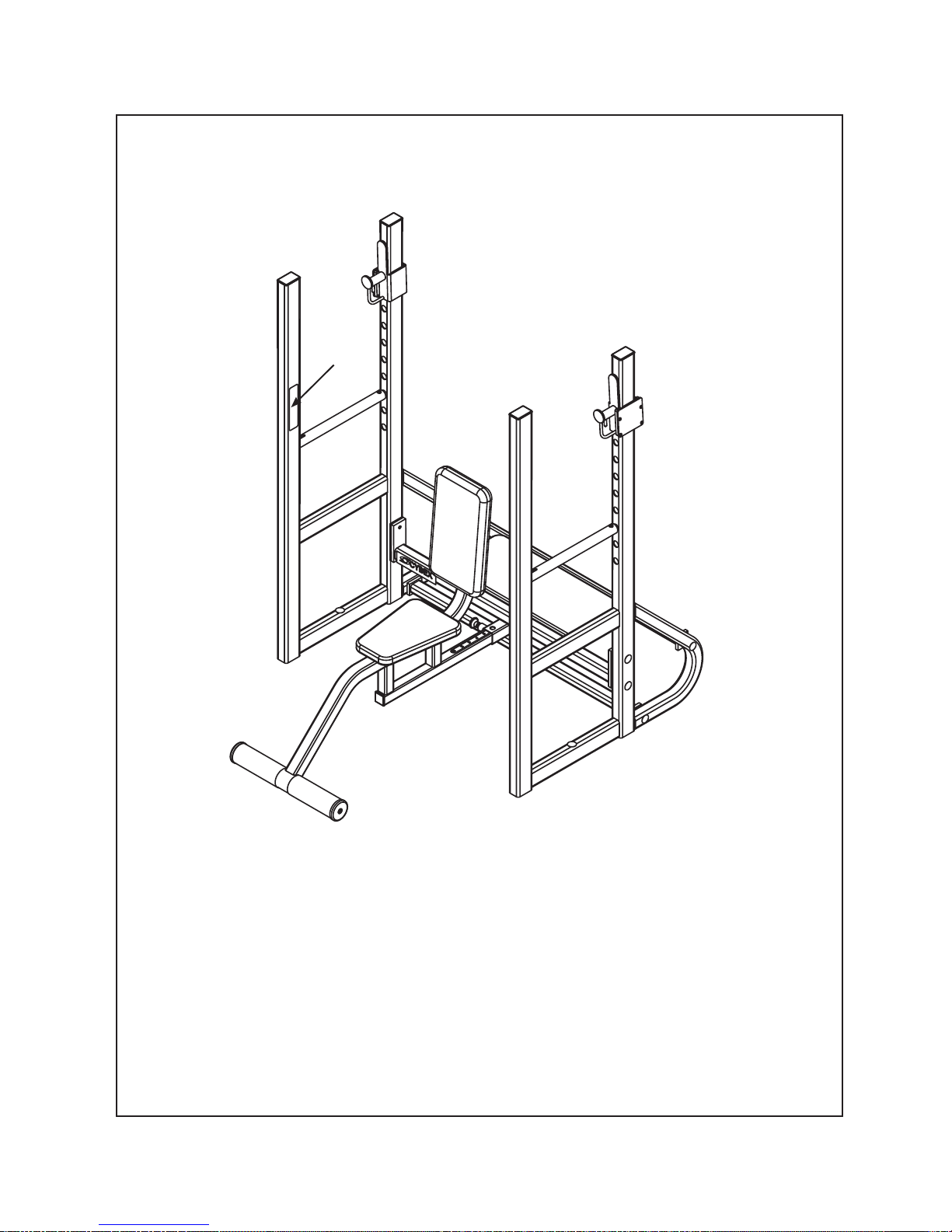
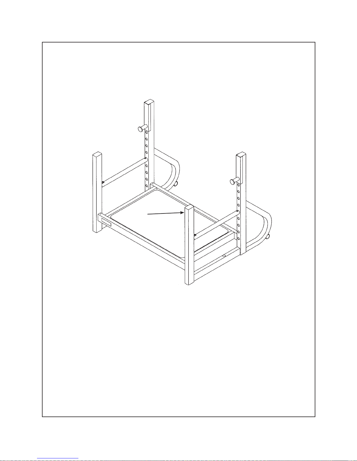
4. Install lower brace (see steps 4A - 4D and Figures 3 and 4).
Locate one lower brace (#4), 4 SHCS .50-13 x 3.00 (#7) and 4 locknuts .50-13 (#9).
A.
Position lower brace (#4) to left (#1) or right side assembly (#2).
B.
Using two SHCS .50-13 x 3.00 (#7) and two locknuts .50-13 (#9) attach one side of lower brace
C.
(#4) to one of the sides (#1 or #2) as shown in Figure 3. Do not tighten hardware at this time.
Repeat Steps 4B and 4C to attach other side. See Figure 4. Do not tighten hardware at this time.
D.
7
Figure 3
9
4
9
1
2
7
9
4
1
Figure 4
9
Assembly
Page 5-19
Page 76

Cybex Free Weight Owner’s Manual
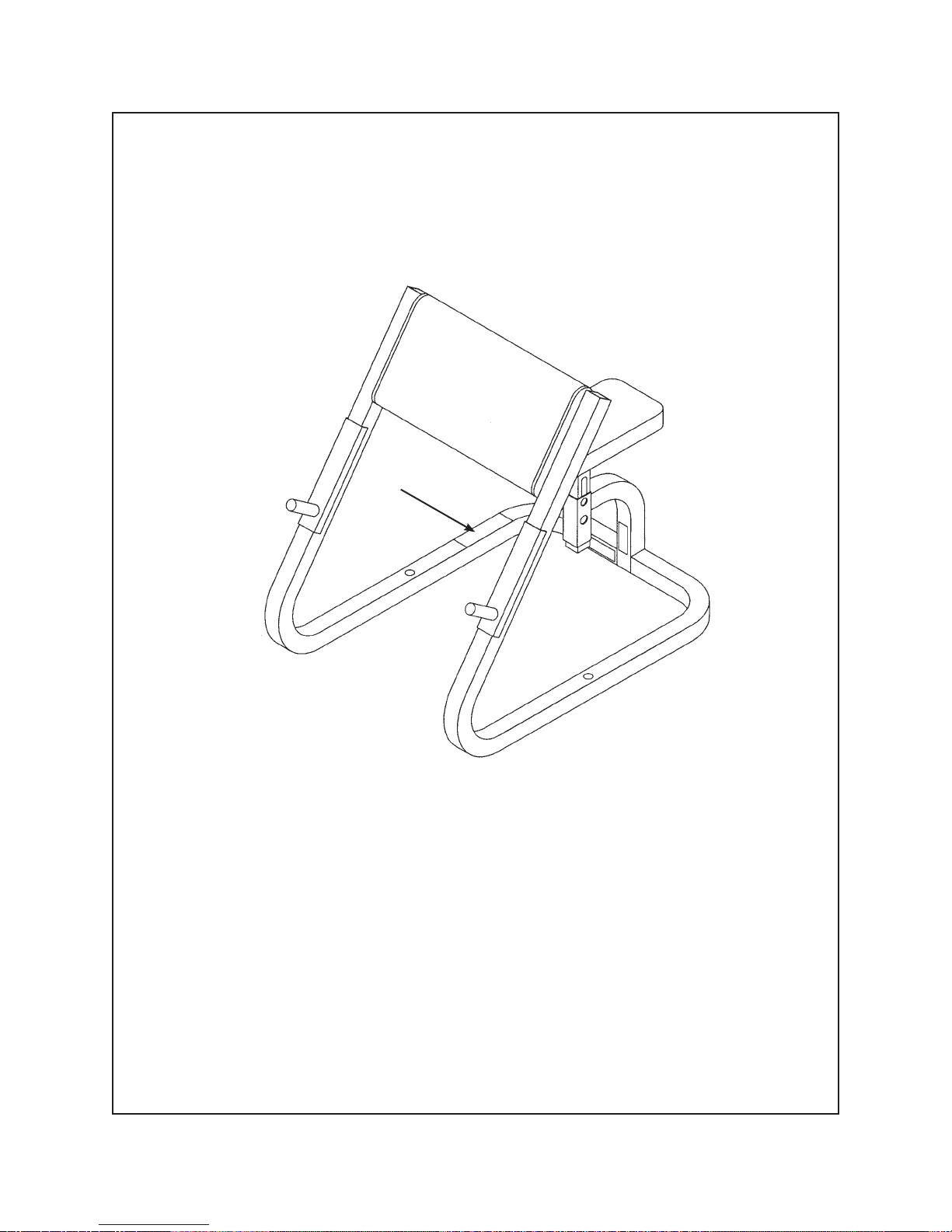
5. Install upper brace (see steps 5A - 5D and Figures 5 and 6).
Locate one upper brace (#5), four SHCS .50-13 x 3.00 (#7) and four locknuts .50-13 (#9).
A.
Position upper brace (#5) to left (#1) or right side assembly (#2).
B.
Attach one side of upper brace (#5) to one of the sides (#1 or #2) as shown in Figure 5 using two
C.
SHCS .50-13 x 3.00 (#7) and two locknuts .50-13 (#9). Do not tighten hardware at this time.
9
5
9
7
2
1
Figure 5
Repeat Steps 5B and 5C to attach other side. See Figure 6. Securely tighten all hardware at
D.
this time.
7
4
9
1
Figure 6
Assembly
Page 5-20
9
2
Page 77

Cybex Free Weight Owner’s Manual
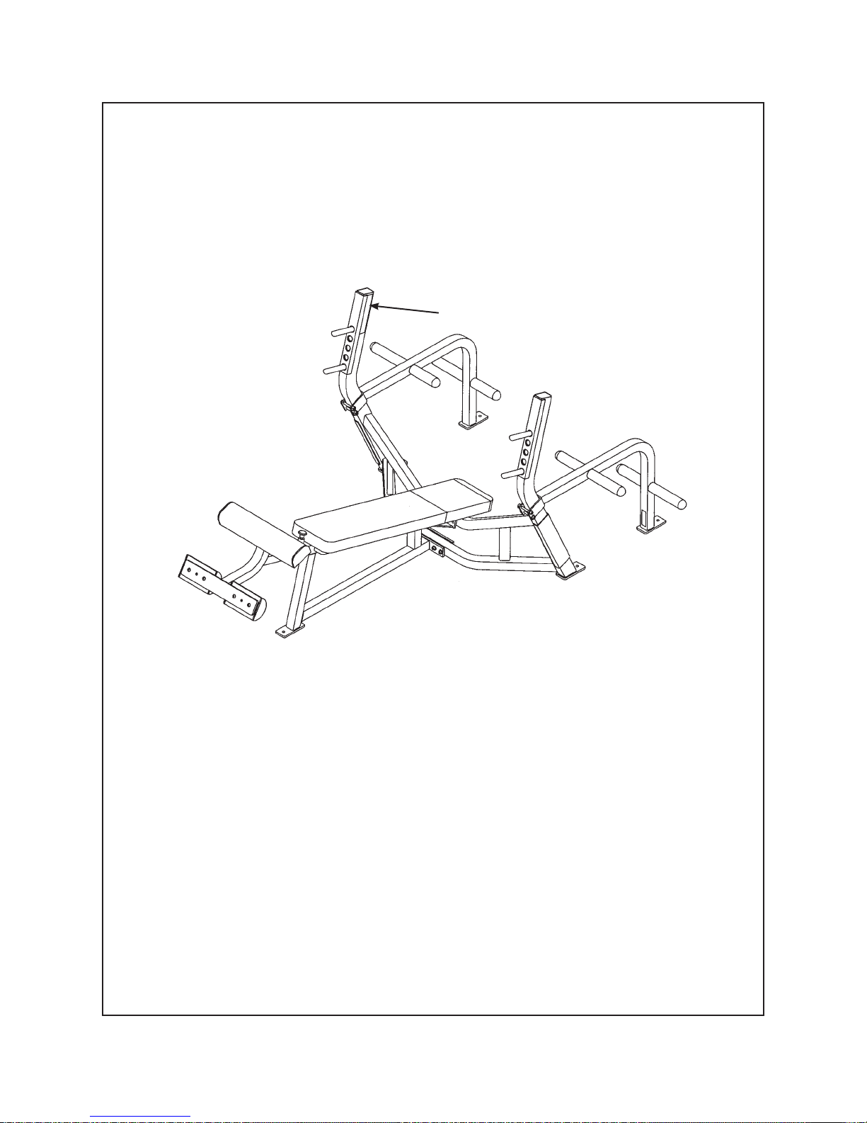
NOTE: When upgrading an existing Squat Rack (5570) to include the Adjustable Stop (5572) remove
items 11 - 15. See Figure 7.
14
14
11
12
15
13
11
11
15
13
12
11
Figure 7
6. Install bar stop to squat rack (see steps 6A - 6C and Figures 5 and 6).
Locate two bar stops (#6), two hole plugs (#24), four SHCS .50-13 x 4.00 (#8) and four locknuts
A.
.50-13 (#9).
Attach one bar stop (#6) to left or right hand side assembly (#1 or #2) using two SHCS .50-13 x
B.
4.00 (#8), one hole plug (#24) and two locknuts .50-13 (#9). See Figure 9.
9
1
Figure 9
24
8
8
6
Assembly
Page 5-21
Page 78

Cybex Free Weight Owner’s Manual
Repeat Step 6B to attach other side. See Figure 10.C.
2
9
8
8
1
24
6
Figure 10
Assembly
Page 5-22
Page 79

Cybex Free Weight Owner’s Manual
6 - Maintenance
All preventive maintenance activities must be performed on a regular basis. Performing routine
preventive maintenance actions can aid in providing safe, trouble-free operation of your Cybex Free
Weight equipment.
NOTE: Cybex is not responsible for performing regular inspection and maintenance actions for your
machines. Instruct all personnel in equipment inspection and maintenance actions and also
in accident reporting/recording. Cybex phone representatives are available to answer any
questions or concerns that you may have.
Cybex will void warranty if
non-Cybex replacement parts
are used.
Maintenance
Page 6-1
Page 80

Cybex Free Weight Owner’s Manual
Daily Procedures
1. Upholstery - Wipe down all upholstery as per the recommendations listed below for light soiling and
more diffi cult stains.
Light Soiling
A solution of 10% household liquid dish soap with warm water applied with a soft damp cloth.
•
If necessary, a solution of liquid cleanser and water applied with a soft bristle brush. Wipe away
•
the residue with a water dampened cloth.
More Diffi cult Stains
Dampen a soft white cloth with a solution of household bleach (sodium hypochlorite),
•
10 % bleach, 90% water. Rub gently. Rinse with a water dampened cloth to remove bleach
concentration.
The same procedure can be used with full strength household bleach, if necessary.
•
Allow bleach to puddle on the affected area or apply with a soaked cloth for approximately
•
30 minutes. Rinse with a water dampened cloth to remove any remaining bleach concentration.
Alternative Method for Diffi cult Stains
Dampen a soft white cloth with rubbing alcohol and rub gently. Rinse with a water dampened
•
cloth to remove any remaining rubbing alcohol concentration.
NOTE: To restore luster, a light coat of spray furniture wax can be used. Apply for 30 seconds and
follow with a light buffi ng using a clean white cloth.
Please Review Carefully
When using strong cleaning agents such as rubbing alcohol or bleach, it is advisable to fi rst test in an
inconspicuous area. Other cleaning agents may contain harsh or unknown solvents and are subject to
formula changes by the product manufacturer without notice. Should you desire to use other cleaning
agents, carefully try them in an inconspicuous area to determine potential damage to the material. Never
use harsh solvents or cleaners which are intended for industrial applications. To clean stained or soiled
areas, a soft white cloth is recommended. Avoid use of paper towels.
Cleaning products may be harmful/irritating to your skin, eyes, etc. Use protective gloves and eye
protection. Do not inhale or swallow any cleaning product. Protect surrounding area/clothing from
exposure. Use in a well ventilated area. Follow all product manufacturer’s warnings. Cybex and its
vendors cannot be held responsible for damage or injuries resulting from the use or misuse of cleaning
products.
Maintenance
Page 6-2
Page 81

Cybex Free Weight Owner’s Manual
1. Frames - Wipe down frame using a mild solution of warm water and car wash soap. Be sure to dry
thoroughly. AVOID acid or chlorine based cleaners and also cleaners containing abrasives as these
could scratch or damage the equipment.
2. Chrome - Clean chrome tubes, fi rst using chrome polish and then using a car wax seal. Neutral
cleaners with a pH between 5.5 and 8.5 are recommended. Be sure to dry thoroughly. AVOID acid
or chlorine based cleaners and also cleaners containing abrasives as these could scratch or damage
the equipment.
Weekly Procedures
1. Inspect all nuts and bolts for looseness. Tighten as required.
2. Inspect handles for wear, paying particular attention to connecting points.
! CAUTION: Replace all worn handles immediately.
3. Inspect all labeling for readability. This includes instructional placards, warning and caution decals.
Replace all worn labeling immediately.
NOTE: Correct all improper alignment and operation issues immediately.
“As Required” Procedures
1. Inspect grips and replace as necessary. See Chapter 7 for replacing grips.
Maintenance
Page 6-3
Page 82

Cybex Free Weight Owner’s Manual
This page intentionally left blank.
Maintenance
Page 6-4
Page 83

Cybex Free Weight Owner’s Manual
7 - Service
Please refer to the next several pages for parts lists and exploded-view diagrams.
Cybex will void warranty if
non-Cybex replacement parts
are used.
Service
Page 7-1
Page 84

Cybex Free Weight Owner’s Manual
Grip Replacement
Bent Leg Ab Board
Check grips and replace worn grips as appropriate. This procedure is for replacing the grip located on the
Bent Leg Ab Board. See item H on the Bent Leg Ab Board Parts List sheet for location of grip.
1. Remove grip by carefully cutting it using a utility knife. NOTE: Be sure that all of the grip is removed.
2. Slide new grip onto bar.
Incline Bench
Olympic Bench Press
Check grips and replace worn grips as appropriate. This procedure is for replacing the grips located on
the Incline Bench and the Olympic Incline Bench. See the appropriate Parts List sheet for location of the
appropriate grip.
1. Remove grip by carefully cutting it using a utility knife. NOTE: Be sure that all of the grip is removed.
2. Place a generous amount of super glue inside new grip.
3. Slide grip into place. NOTE: The glue will set fast. If you do not place the grip on properly, then
repeat this procedure.
45 Degree Back Extension
Dip/Chin Station
Leg Raise Chair
Check grips and replace worn grips as appropriate. This procedure is for replacing any grip located on
the 45 Degree Back Extension, Dip/Chin Station or the Leg Raise Chair. See the appropriate Parts List
sheet for location of the appropriate grip.
1. Remove grip by carefully cutting it with a utility knife.
2. Spray lacquer inside grip.
3. Slide grip into place and work out all air bubbles.
Parts List and Diagrams
See the following pages for each machine.
Service
Page 7-2
Page 85

Cybex Free Weight Owner’s Manual
Bent Leg Ab Board
Product No. 5208 Parts List
K
I
D
H
I (see inset)
L
C
J
D (see inset)
F
E
A
K
(see inset)
B
DESCRIPTION PART NO.
Contour Cushion .............5208S069-0
A.
Leg Cushion ....................5208S060-0
B.
Bench Cushion................5208s052-0
C.
Cybex Decal Black ..........3900-445
D.
Cybex Decal Silver..........3900-446
D.
Right Placard Decal ........5208Y083
E.
Caution Decal .................CM000219
F.
G
DESCRIPTION PART NO.
Foot Pedal Grip ................PP400200
G.
Grip ..................................5208M046
H.
Serial Number Decal
I.
Left Placard Decal............5208Y084
J.
Warning Decal .................5220-364
K.
Adjusting Tube Decal .......5208-302
L.
Service
Page 7-3
Page 86

Service
Page 7-4
Cybex Free Weight Owner’s Manual
5208 - Bent Leg Ab Board
ITEM QTY PART NO. DESCRIPTION
1 1 4000M218 Detent Pin
2 1 5208M040 Lower Pivot Shaft
3 1 5208M041 Upper Pivot Shaft
4 1 5208P042 Adjusting Post
5 1 5208P043 Spring Guide Rod
6 1 5208P044 Latch Bolt
7 2 5208M045 Wear Pad
8 1 5208M046 Grip 12.75 L
9 2 5208P048 Spacer
10 1 5208Y083 Right Hand Placard Decal
11 1 5208Y084 Left Hand Placard Decal
12 1 BS070201 Compression Spring .56 x .66 x .50 L
13 3 BS110200 Die Spring 1.23 x .65 x 2.07 L
14 1 3900-445 Cybex Decal 1.00 Horiz. Black
14 1 3900-446 Cybex Decal 1.00 Horiz. Silver
14 Removed 7-03
15 2 CM000219 Angle Adjust Caution Decal
16 1 FB030211 Cam Follower Bearing .75
17 2 FB050209 Flange Bearing 1.00 x 1.25 x .75 L
18 1 HC621228 HHCS .25-20 x 2.25
19 1 HC702822 SHCS .375-16 x 1.50
20 2 HC701224 HHCS .375-16 x 1.75
21 1 HD403326 Shoulder Bolt .625 x 2.00 .50-13
22 1 HD423348 Shoulder Bolt .75 x 4.75 .625-11
23 1 HN624100 Hex Nut .25-20
24 1 HN784000 Hex Nut .50-13
25 4 HN814400 Jam Nut .625-11
26 1 HS308300 Split Lockwasher .25
27 1 GP000002 Pulley Shoulder Adapter
28 2 HS348300 Split Lockwasher .375
29 10 HT102214 Tap Screw #10-12 x .625 A (Phillips)
30 2 HY662912 Set Screw .312-18 x .50 Cup point
31 1 JN714200 Hex Nut .375-24
32 1 JN814200 Hex Nut .625-11
33 4 JS407100 Machinery Bushing .625
34 1 JS408400 Split Lockwasher .625
35 4 PN660200 Plastic Insert 1.00 Dia. x 11 G
36 3 PP080202 Plastic Insert 1.19 Dia. x 11 G
37 4 PP090001 Plastic Insert 1.50 x 2.50 x 11 G
38 1 PP090210 Plastic Insert 2.00 Sq x 10-14 G
39 1 PP090202 Plastic Insert 1.50 x 3.00 x 11 G
40 2 PP400200 Foot Pedal Grip
41 1 PP460200 Plastic Knob .312-18
42 1 PR060003 Recess Bumper
43 2 PP080207 Plastic Insert .437 Dia. x 11 G
44 2 5208C049 Guard
45 1 HN784400 Jam Nut .50-13
46 1 5208W002 Base
47 1 5208W008 Bench
48 1 5208W017 Adjusting Tube
49 1 5208W020 Foot Lever
50 1 5208W026 Lower Adjustment
51 1 5208W037 Cushion Plate
52 1 5208S052-0 Bench Cushion
53 1 5208S060-0 Leg Cushion
54 1 5208S069-0 Contour Cushion
55 2 HC701236 HHCS .375-16 x 3.25
56 2 HS010000 Screw Cap Washer .375
57 8 JC700420 BHSCS .375-16 x 1.25
58 4 JC700936 FHSCS .375-16 x 3.25
59 2 PP080005 Screw Cap
60 1 4121K117 Detent Pin Kit
61 1 5220-364 Warning Decal
62 1 5208-302 Adjusting Tube Decal
63 1 51198 Strength Warranty Sheet (not shown)
64 10 JS347400 Internal Tooth Lockwasher
Page 87

Cybex Free Weight Owner’s Manual
5208 - Bent Leg Ab Board
Service
Page 7-5
Page 88

Cybex Free Weight Owner’s Manual
This page intentionally left blank.
Service
Page 7-6
Page 89

Cybex Free Weight Owner’s Manual
Olympic Bench Press/Weight Storage Attachment
Product No. 5362 and 5363 Parts List
D
C
B
A
G
NOTE: See exploded-view diagram for item E (serial number decal).
F
DESCRIPTION PART NO.
A.
Cushion
w/ Wear Cover .................01035
B.
Cybex Decal Black ...........3900-445
B.
Cybex Decal Silver...........3900-446
DESCRIPTION PART NO.
Wear Cover (Item A) .......4000S118-0
C.
Warning Decal ................5220-364
D.
Serial Number Decal
E.
Serial Number Decal
F.
Rubber Grip ....................4140-329
G.
Service
Page 7-7
Page 90

Cybex Free Weight Owner’s Manual
5362 and 5363 - Olympic Bench Press/Weight Storage Attachment
ITEM QTY PART NO. DESCRIPTION
1 1 3900-445 Cybex Decal 1.00 Horiz. Black
1 Removed 7-03
1 1 3900-446 Cybex Decal 1.00 Horiz. Silver
2 1 5362-200 Back Frame
3 1 5362-201 Cushion Support Frame
4 2 5362-311 Machined Bumper
5 2 5362-312 Machined Bumper
6 4 5570-206 Detent Pin
7 8 HN704901 Nylon Locknut .375-16
8 8 HS347600 Washer SAE .375
9 8 JC702836 SHCS .375-16 x 3.25
10 2 PP090206 Plastic Insert
11 2 4140-329 Rubber Grip 5.00 L
12 1 01035 Cushion with Wear Cover
5362 and 5363 - Olympic Bench Press/Weight Storage Attachment
ITEM QTY PART NO. DESCRIPTION
13 2 JC700434 BHSCS .375-16 x 3.00
14 8 5330M040 Plug
15 4 5340P003 Weight Tube 6.00 L
16 1 5363-200 Frame - Right Side
17 4 5490P010 Weight Tube 8.00 L
18 4 HN704901 Nylon Locknut .375-16
19 4 JC702836 SHCS .375-16 x 3.25
20 4 HS347600 Washer SAE .375
21 1 5363-200 Frame - Left Side
22 1 4000S118-0 Wear Cover
23 1 5220-364 Warning Decal
24 8 5220-367 Spacer
25 1 51198 Strength Warranty Sheet (not shown)
26 2 JS347400 Internal Tooth Lockwasher
5363 OPTIONAL
WEIGHT STORAGE
ATTACHMENT
5362
OLYMPIC
BENCH
PRESS
Service
Page 7-8
Page 91

Cybex Free Weight Owner’s Manual
Olympic Incline Bench Press/Weight Storage Attachment
Product No. 5372 and 5363 Parts List
G
D
A
C
E
NOTE: See exploded-view diagram for item F (serial number decal).
DESCRIPTION PART NO.
Cushion
A.
w/Wear Cover (Item B) ....01213
B.
Wear Cover (Item A) ........4000S118-0
C.
Cushion ............................4800-019
D.
Cybex Decal Black ...........3900-443
D.
Cybex Decal Silver ..........3900-444
B
D
H
DESCRIPTION PART NO.
Adjustable Seat Decal.... 5221-316
E.
Serial Number Decal
F.
Warning Decal ...............5220-364
G.
Serial Number Decal
H.
Service
Page 7-9
Page 92

Cybex Free Weight Owner’s Manual
5372 and 5363 - Olympic Incline Bench/Weight Storage Attachment
ITEM QTY PART NO. DESCRIPTION
1 1 4520-212 Seat Roller
2 2 4520-331 Roller
3 Removed
4 Removed 7-03
4 1 3900-443 Cybex Decal 1.57 Horiz. Black
4 1 3900-444 Cybex Decal 1.57 Horiz. Silver
5 2 5362-311 Machined Bumper
6 2 5362-312 Machined Bumper
7 1 5372-200 Frame (back)
8 1 5372-201 Frame (front)
9 1 5372-202 Seat
10 4 5570-206 Detent Pin
11 2 HC702817 SHCS .375-16 x 1.00
12 8 HC704901 Nylon Locknut .375-16
13 Removed
14 8 HS347700 Washer USS .375
15 8 JC702838 SHCS .375-16 x 3.50
16 1 PP090202 Plastic Insert 1.50 x 3.00 x 11 G
17 3 PP090206 Plastic Insert
18 1 5221-316 Adjustable Seat Decal
19 1 01213 Cushion with Wear Cover
ITEM QTY PART NO. DESCRIPTION
20 1 4000S118-0 Wear Cover
21 1 4800-026 Cushion
22 2 JC700434 BHSCS .375-16 x 3.00
23 2 HC700430 BHSCS .375-16 x 2.50
24 8 5330M040 Plug
25 4 5340P003 Weight Tube 6.00 L
26 1 5363-200 Frame - Right Side
27 4 5490P010 Weight Tube 8.00 L
28 4 HN704901 Nylon Locknut .375-16
29 4 JC702836 SHCS .375-16 x 3.25
30 4 HS347600 Washer SAE .375
31 1 5363-200 Frame - Left Side
32 1 5220-364 Warning Decal
33 8 5220-367 Spacer
34 1 4520-213 Pulley Bracket
35 1 4520-362 Seat Caution Decal
36 2 HS347600 Washer SAE .375
37 2 JC702812 SHCS .375-16 x .50
38 1 51198 Strength Warranty Sheet (not shown)
39 2 JS347400 Internal Tooth Lockwasher
5372 and 5363 - Olympic Incline Bench Press/Weight Storage Attachment
5363
OPTIONAL
5372
OLYMPIC
INCLINE
BENCH
17
7
5
10
10
6
19
20
4
8
SERIAL NUMBER
DECAL
39
32
17
5
10
10
6
WEIGHT
STORAGE
ATTACHMENT
18
21
16
39
23
9
11
2
1
37
14
34
Service
Page 7-10
17
22
39
36
15
22
14
37
35
28
14
Page 93

Cybex Free Weight Owner’s Manual
Beauty Bell Rack
Product No. 5375 Parts List
NOTE: See exploded-view diagram for item B (serial number decal).
DESCRIPTION PART NO.
Cybex Decal Black ...........3900-445
A.
A. Cybex Decal Silver...........3900-446
A
DESCRIPTION PART NO.
Serial Number DecalB.
Service
Page 7-11
Page 94

Cybex Free Weight Owner’s Manual
5375 - Beauty Bell Rack
ITEM QTY PART NO. DESCRIPTION
1 2 3900-445 Cybex Decal 1.00 Horiz. Black
1 2 3900-446 Cybex Decal 1.00 Horiz. Silver
2 1 5375-200 Frame
3 2 5375-301 Plastic Guard
4 12 HN704901 Nylon Locknut .375-16
5 Removed
6 12 JC700920 FHSCS .375-16 x 1.25
7 12 PP030200 Dumbbell Saddle
8 2 PP240204 Rubber Edge Trim 37.88” L
9 76” YD000016 Double Coated Tape
5375 - Beauty Bell Rack
Service
Page 7-12
Page 95

Cybex Free Weight Owner’s Manual
Twin Tier Dumbbell Rack
Product No. 5380 Parts List
NOTE: See exploded-view diagram for item B (serial number decal).
DESCRIPTION PART NO.
Cybex Decal Black ...........3900-445
A.
A. Cybex Decal Silver...........3900-446
A
DESCRIPTION PART NO.
Serial Number DecalB.
Service
Page 7-13
Page 96

Cybex Free Weight Owner’s Manual
5380 - Twin Tier Dumbbell Rack
ITEM QTY PART NO. DESCRIPTION
1 1 5380W002 Frame
2 40 HN704901 Nylon Locknut .375-16
3 Removed
4 40 JC700920 FHSCS .375-16 x 1.25
5 40 PP030200 Dumbbell Saddle
6 2 3900-445 Cybex Decal 1.00 Horiz. Black
6 2 3900-446 Cybex Decal 1.00 Horiz. Silver
5380 - Twin Tier Dumbbell Rack
Service
Page 7-14
Page 97

Cybex Free Weight Owner’s Manual
Single Tier Dumbbell Rack
Product No. 5385 Parts List
NOTE: See exploded-view diagram for item B (serial number decal).
DESCRIPTION PART NO.
Cybex Decal Black ...........3900-445
A.
A. Cybex Decal Silver...........3900-446
A
DESCRIPTION PART NO.
Serial Number DecalB.
Service
Page 7-15
Page 98

Cybex Free Weight Owner’s Manual
5385 - Single Tier Dumbbell Rack
ITEM QTY PART NO. DESCRIPTION
1 1 5385W002 Frame
2 20 HN704901 Nylon Locknut .375-16
3 Removed
4 20 JC700920 FHSCS .375-16 x 1.25
5 20 PP030200 Dumbbell Saddle
6 2 3900-445 Cybex Decal 1.00 Horiz. Black
6 2 3900-446 Cybex Decal 1.00 Horiz. Silver
5385 - Single Tier Dumbbell Rack
Service
Page 7-16
Page 99

Cybex Free Weight Owner’s Manual
45 Degree Back Extension
Product No. 5411 Parts List
A, B
C
I, J
F
E
D
NOTE: See exploded-view diagram for item G (serial number decal) and H.
DESCRIPTION PART NO.
Cushion w/Wear Cover ....01214
A.
Wear Cover (Item A) ........5410S024-0
B.
Grip ..................................PR400202
C.
Cybex Decal Black ...........3900-445
D.
Cybex Decal Silver...........3900-446
D.
Non-Slip Fabric ................5411-309
E.
DESCRIPTION PART NO.
General Warning Decal ....5220-364
F.
Serial Number Decal
G.
Adjusting Tube Decal .......5411-312
H.
Cushion w/Wear Cover ....01215
I.
Wear Cover (Item I) .........5450S037-0
J.
Service
Page 7-17
Page 100

Cybex Free Weight Owner’s Manual
5411 - 45 Degree Back Extension
ITEM QTY PART NO. DESCRIPTION
1 1 PP460010 Plastic Knob
2 1 4000-328 Footglide Removal Instr.
(not shown)
3 1 4000M218 Detent Pin
4 Removed 7-03
5 1 5220-364 Warning Decal
6 3 5410M012 Machined Bumper
7 1 5411-200 Frame
8 1 5411-201 Handle Bar
9 1 5411-202 Adjusting Tube
10 2 5411-309 Non-Slip
11 1 5411-312 Adjusting Tube Decal
12 1 AA033904 V-Pusher
13 1 BS070201 Com Spring .56 x .66 x 1.50 L
14 2 01214 Cushion with Wear Cover
15 4 HC700420 BHSCS .375-16 x 1.25
16 2 HC700430 BHSCS .375-16 x 2.50
17 2 HF449063 Connector Insert .75 x .25-20
ITEM QTY PART NO. DESCRIPTION
18 1 HM532812 SHCS .138/6-32 x .50 GR8
19 2 HN704901 Nylon Locknut .375-16
20 4 HS347600 Washer SAE .375
21 4 JC700422 BHSCS .375-16 x 1.50
22 1 JC702814 SHCS .375-16 x .625
23 2 PP090210 Plastic Insert 2.00 Sq x 10-14 G
24 1 3900-445 Cybex Decal 1.00 Horiz. Black
24 Removed 7-03
24 1 3900-446 Cybex Decal 1.00 Horiz. Silver
25 1 PP460200 Plastic Knob .312-18
26 20.5” PR400202 Grip 1.38 OD x .94
27 2 01215 Cushion with Wear Cover
28 1 4705-332 Threaded Insert
29 2 11090-374 End Cap
30 2 11090-376 Handle Grip Ring
31 1 51198 Strength Warranty Sheet (not shown)
32 2 JC620422 BHSCS .250-20 x 1.50
33 8 JS347400 Internal Tooth Lockwasher
5411 - 45 Degree Back Extension
Service
Page 7-18
 Loading...